Nissan Pathfinder: Engine Control System - Dtc/circuit Diagnosis
- Trouble Diagnosis - Specification Value
- Power Supply and Ground Circuit
- 3993 C053c Wheel Speed Sensor
- 3993 U0101 Can Comm Circuit
- 3993 U0122 Vehicle Dynamics Control Module
- 3993 U012e Engine Communication
- 3993 U0155 Can Communication (ipc)
- 3993 U0284 Active Grille Shutter
- 3993 U1000 Can Communication Circuit
- 3993 U1040 Eng Comm Circuit
- 3993 U1327 Mac Key
- 3993 U2118 Can Comm Circuit
- 3993 U2141 Can Comm Circuit
- 3994 P0011 Intake Valve Timing Control
- 3994 P0014 Evt Control
- 3994 P0030 A/f Sensor 1 Heater
- 3994 P0078 Evt Control Solenoid Valve
- 3994 P0087 Frp Control System ++
- 3994 P00d2 Ho2s2 Heater
- 3994 P00fe Evap Control System
- 3994 P0101 Maf Sensor
- 3994 P0107 Barometric Pressure Sensor
- 3994 P0111 Iat Sensor
- 3995 P0116 Engine Coolant Temperature Sensor
- 3995 P0122 Tp Sensor
- 3995 P0127 Iat Sensor
- 3995 P0128 Thermostat Function
- 3995 P0130 A/f Sensor 1
- 3995 P0138 Ho2s2
- 3995 P0171 Fuel Injection System Function
- 3995 P0181 Ftt Sensor
- 3995 P01f0 Engine Coolant Temperature
- 3995 P025b Fuel Pump Module a
- 3996 P026b Injection Timing
- 3996 P0300 Misfire
- 3996 P0315 Crankshaft Position
- 3996 P0326 Knock Sensor
- 3996 P0327 Ks
- 3996 P0335 Crankshaft Position Sensor
- 3996 P0340 Cmp Sensor
- 3996 P0365 Exhaust Camshaft Position Sensor
- 3996 P0385 Ckp Sensor 2
- 3996 P0420 Three Way Catalyst Function
- 3997 P0441 Evap Control System
- 3997 P0443 Evap Canister Purge Volume Control Solenoid Valve
- 3997 P0447 Evap Canister Vent Control Valve
- 3997 P0450 Evap Control System Pressure Sensor
- 3997 P0461 Fuel Level Sensor
- 3997 P0500 Vss
- 3997 P0506 Isc System
- 3997 P050a Cold Start Control
- 3997 P0520 Eop Sensor
- 3997 P0524 Engine Oil Pressure
- 3998 P0532 A/c Refrigerant Pressure Sensor
- 3998 P055f Engine Oil Pressure
- 3998 P0573 Brake Pedal Switch a
- 3998 P059f Active Grille Shutter
- 3998 P0606 Ecm
- 3998 P0611 Ecm Protection
- 3998 P062b Ecm
- 3998 P062f Control Module
- 3998 P0643 Sensor Power Supply
- 3998 P064d Ecm
- 3999 P06da Engine Oil Pressure Control Solenoid Valve
- 3999 P06dd Variable Oil Pressure Valve
- 3999 P06e6 Internal Control Module
- 3999 P0719 Brake Pedal Switch B
- 3999 P0850 Pnp Switch
- 3999 P1140 Intake Camshaft Position Sensor
- 3999 P1148 Closed Loop Control
- 3999 P1197 Out of Gas
- 3999 P119a Fuel Rail Pressure Sensor
- 3999 P1217 Engine Over Temperature
- 4000 P1220 Fuel Pump Control Module (fpcm)
- 4000 P1225 Tp Sensor
- 4000 P12a9 Hvac Communication
- 4000 P1526 Ascd System
- 4000 P155b Energy Management Control
- 4000 P155d Generator
- 4000 P1564 Ascd Steering Switch
- 4000 P1568 Icc Function
- 4000 P1572 Brake Pedal Position Switch
- 4000 P1574 Ascd Vehicle Speed Sensor
- 4001 P1575 Brake Switch
- 4001 P159f Active Grille Shutter
- 4001 P1603 Ecm
- 4001 P161d Immobilizer
- 4001 P1650 Starter Motor Relay 2
- 4001 P1800 Vias Control Solenoid Valve 1
- 4001 P1805 Stop Lamp Switch
- 4001 P1a10 Ecm Initial Learning Incomplete
- 4001 P2100 Throttle Control Motor Relay
- 4001 P2101 Electric Throttle Control Function
- 4002 P2118 Throttle Control Motor
- 4002 P2119 Electric Throttle Control Actuator
- 4002 P2122 App Sensor
- 4002 P2138 App Sensor
- 4002 P219a Air Fuel Ratio
- 4002 P2297 Air Fuel Ratio Sensor 1
- 4002 P25df Electric Intake Valve Timing Control Motor
- 4002 P2610 Ecm Internal Timer
- 4002 P2b96 Injection Pulse
- 4002 P34ac Electric Intake Valve Timing Control Actuator
- 4003 Active Grille Shutter
- 4003 Ascd Indicator
- 4003 Cooling Fan
- 4003 Crankshaft Position Sensor 2
- 4003 Electrical Load Signal
- 4003 Electronic Controlled Engine Mount
- 4003 Fuel Injector
- 4003 Fuel Pump
- 4003 High Pressure Fuel Pump
- 4004 Ignition Signal
- 4004 Information Display (ascd)
- 4004 Malfunction Indicator Lamp
- 4004 Mass Air Flow Sensor
- 4004 On Board Refueling Vapor Recovery (orvr)
- 4004 Refrigerant Pressure Sensor
- 4004 Sensor Power Supply 2 Circuit
- 4004 Variable Induction Air System
Trouble Diagnosis - Specification Value Nissan Pathfinder 2026
Component Function Check
PRECONDITIONING
 With CONSULT
Make sure that all of the following conditions are satisfied.
TESTING CONDITION
-
Nissan Pathfinder Vehicle driven distance: More than 5,000 km (3,107 miles)
-
Barometric pressure: 98.3 – 104.3 kPa (1.003 – 1.064 kg/cm2, 14.25 – 15.12 psi)
-
Atmospheric temperature: 20 – 30°C (68 – 86°F)
-
Engine coolant temperature: 75 – 95°C (167 – 203°F)
-
Transmission: Warmed-up
-
After the engine is warmed up to normal operating temperature, drive Nissan Pathfinder vehicle until “FULUD TEMP” in “Data Monitor” of “TRANSMISSION” indicates more than 60°C (140°F).
-
Electrical load: Not applied
-
Rear window defogger switch, air conditioner switch, lighting switch are OFF. Steering wheel is straight ahead.
-
-
Engine speed: Idle
>>
GO TO 2.
CHECK REFERENCE OF DATA MONITOR MODE
 With CONSULT
 NOTE:
NOTE:
Check “Reference” of “Data Monitor” mode in maximum scale display.
-
Perform Work Procedure.
-
On CONSULT screen, select “ENGINE”>>“Data Monitor”.
-
Select “Reference” and change “DISPLAY TYPE” to “Line Graph”.
-
Select “B/FUEL SCHDL”, “A/F ALPHA-B1”, “A/F ALPHA-B2”, and “MASS AIR FLOW SENSOR (Hz)”.
-
Make sure that monitor items are within the Reference.
Is the measurement value within the Reference?
YES>>
INSPECTION END
NO>>
Proceed to Diagnosis Procedure.
Diagnosis Procedure
The specification Reference indicated at “Reference” of “Data Monitor” mode indicates the tolerance of the ECM input/output valve when the engine control system operates normally.
 NOTE:
NOTE:
The Reference is indicated when "DISPLAY TYPE" is "Line Graph".
When the indicated value on “Data Monitor” mode is within the Reference, the engine control system is confirmed OK. When the indicated value on “Data Monitor” mode is not within the Reference, the engine control system may have one or more malfunctions.
The Reference is used to detect malfunctions that may affect the engine control system, but will not illuminate the MIL.
The Reference will be displayed for the following three items:
-
B/FUEL SCHDL (The fuel injection pulse width programmed into ECM prior to any learned on board correction)
-
A/F ALPHA-B1/B2 (The mean value of air-fuel ratio feedback correction factor per cycle)
-
MASS AIR FLOW SENSOR (Hz) (The frequency of the mass air flow sensor)
OVERALL SEQUENCE
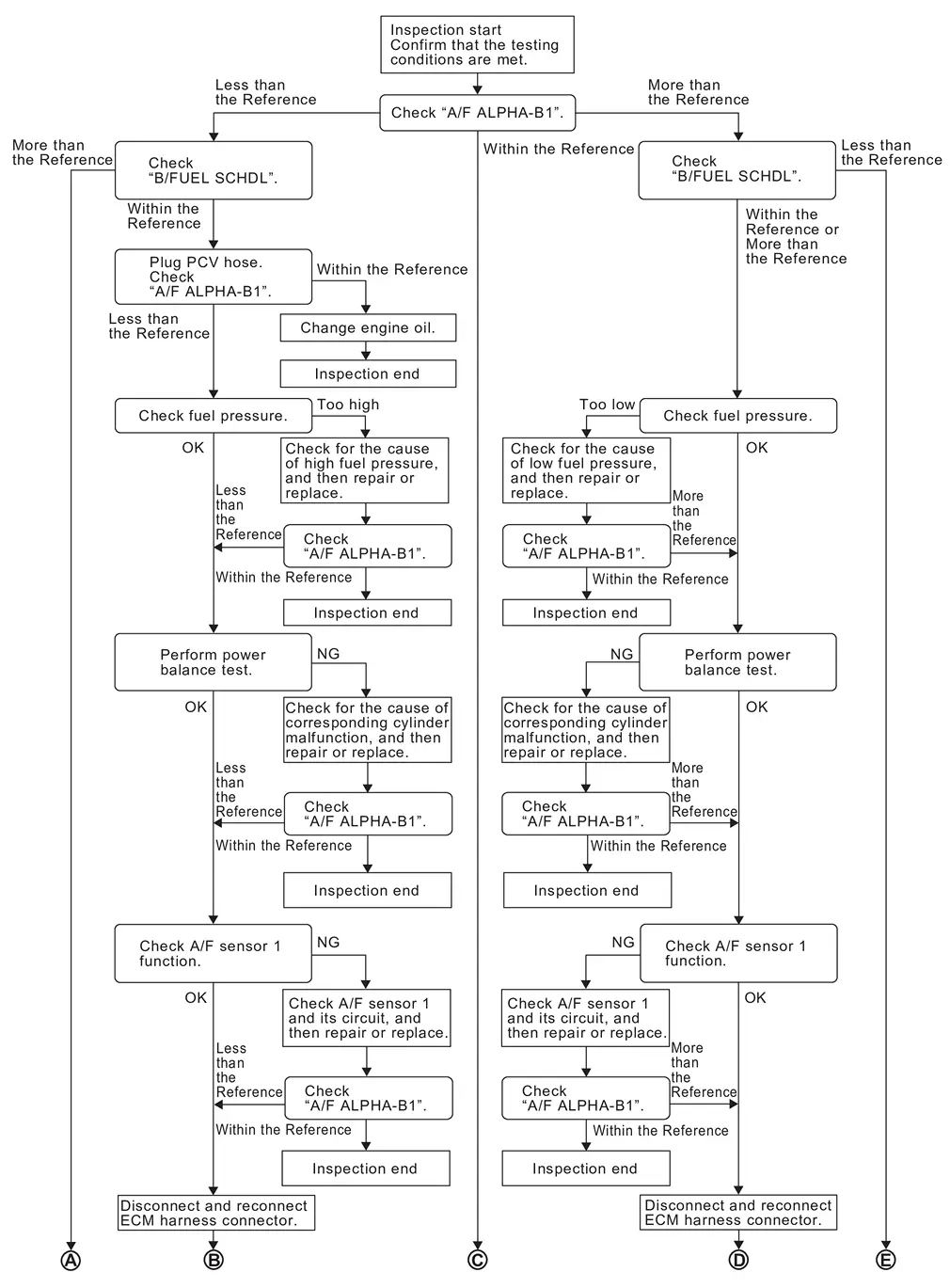
DETAILED PROCEDURE
CHECK “A/F ALPHA-B1” AND “A/F ALPHA-B2”
 With CONSULT
-
Start engine.
-
Confirm that the testing conditions are met. Refer to Component Function Check.
-
On CONSULT screen, select “ENGINE”>>“Data Monitor”.
-
Select “Reference” and change “DISPLAY TYPE” to “Line Graph”.
-
Select “A/F ALPHA-B1” and “A/F ALPHA-B2”.
-
Make sure that each indication is within the Reference.
 NOTE:
NOTE: Check “A/F ALPHA-B1”, “A/F ALPHA-B2” for approximately 1 minute because they may fluctuate. It is NG if the indication is out of the Reference even a little.
Is the measurement value within the Reference?
YES>>
GO TO 17.
NO-1>>
Less than the Reference: GO TO 2.
NO-2>>
More than the Reference: GO TO 3.
CHECK “B/FUEL SCHDL”
 With CONSULT
Select “B/FUEL SCHDL” at “Reference” of “Data Monitor” mode, and make sure that the indication is within the Reference.
Is the measurement value within the Reference?
YES>>
GO TO 4.
NO>>
More than the Reference: GO TO 19.
CHECK “B/FUEL SCHDL”
 With CONSULT
Select “B/FUEL SCHDL” at “Reference” of “Data Monitor” mode, and make sure that the indication is within the Reference.
Is the measurement value within the Reference?
YES>>
GO TO 6.
NO-1>>
More than the Reference: GO TO 6.
NO-2>>
Less than the Reference: GO TO 25.
CHECK “A/F ALPHA-B1” AND “A/F ALPHA-B2”
 With CONSULT
-
Stop the engine.
-
Disconnect PCV hose, and then plug it.
-
Start engine.
-
Select “A/F ALPHA-B1” and “A/F ALPHA-B2” at “Reference” of “Data Monitor” mode, and make sure that the indication is within the Reference.
Is the measurement value within the Reference?
YES>>
GO TO 5.
NO>>
GO TO 6.
CHANGE ENGINE OIL
-
Stop the engine.
-
Change engine oil. Refer to Inspection.
 NOTE:
NOTE: This symptom may occur when a large amount of gasoline is mixed with engine oil because of driving conditions (such as when engine oil temperature does not rise enough since a journey distance is too short during winter). The symptom will not be detected after changing engine oil or changing driving conditions.
>>
INSPECTION END
CHECK FUEL PRESSURE
Check fuel pressure. (Refer to Work Procedure.)
Is the inspection result normal?
YES>>
GO TO 9.
NO-1>>
Fuel pressure is too high: Replace “fuel filter and fuel pump assembly” and then GO TO 8.
NO-2>>
Fuel pressure is too low: GO TO 7.
DETECT MALFUNCTIONING PART
Check fuel hoses and fuel tubes for clogging.
Is the inspection result normal?
YES>>
Replace “fuel filter and fuel pump assembly” and then GO TO 8.
NO>>
Repair or replace and then GO TO 8.
CHECK “A/F ALPHA-B1” AND “A/F ALPHA-B2”
 With CONSULT
-
Start engine.
-
Select “A/F ALPHA-B1” and “A/F ALPHA-B2” at “Reference” of “Data Monitor” mode, and make sure that the indication is within the Reference.
Is the measurement value within the Reference?
YES>>
INSPECTION END
NO>>
GO TO 9.
PERFORM POWER BALANCE TEST
 With CONSULT
-
Perform “POWER BALANCE” in “Active Test” mode.
-
Make sure that the each cylinder produces a momentary engine speed drop.
Is the inspection result normal?
YES>>
GO TO 12.
NO>>
GO TO 10.
DETECT MALFUNCTIONING PART
Check the following bellow.
-
Ignition coil and its circuit (Refer to Component Function Check.)
-
Fuel injector and its circuit (Refer to Component Function Check.)
-
Intake air leakage
-
Low compression pressure (Refer to On-Nissan Pathfinder Vehicle Service.)
Is the inspection result normal?
YES>>
Replace fuel injector and then GO TO 11.
NO>>
Repair or replace malfunctioning part and then GO TO 11.
CHECK “A/F ALPHA-B1” AND “A/F ALPHA-B2”
 With CONSULT
-
Start engine.
-
Select “A/F ALPHA-B1” and “A/F ALPHA-B2” at “Reference” of “Data Monitor” mode, and make sure that the indication is within the Reference.
Is the measurement value within the Reference?
YES>>
INSPECTION END
NO>>
GO TO 12.
CHECK A/F SENSOR 1 FUNCTION
Perform all DTC CONFIRMATION PROCEDURE related with A/F sensor 1.
-
For DTC P0130, P0150, refer to DTC Description.
-
For DTC P0131, P0151, refer to DTC Description.
-
For DTC P0132, P0152, refer to DTC Description.
-
For DTC P014C, P014D, P014E, P014F, P015A, P015B, P015C, P015D, refer to DTC Description.
-
For DTC P2096, P2097, P2098, P2099, refer to DTC Description.
Are any DTCs detected?
YES>>
GO TO 13.
NO>>
GO TO 15.
CHECK A/F SENSOR 1 CIRCUIT
Perform Diagnosis Procedure according to corresponding DTC.
>>
GO TO 14.
CHECK “A/F ALPHA-B1” AND “A/F ALPHA-B2”
 With CONSULT
-
Start engine.
-
Select “A/F ALPHA-B1” and “A/F ALPHA-B2” at “Reference” of “Data Monitor” mode, and make sure that the indication is within the Reference.
Is the measurement value within the Reference?
YES>>
INSPECTION END
NO>>
GO TO 15.
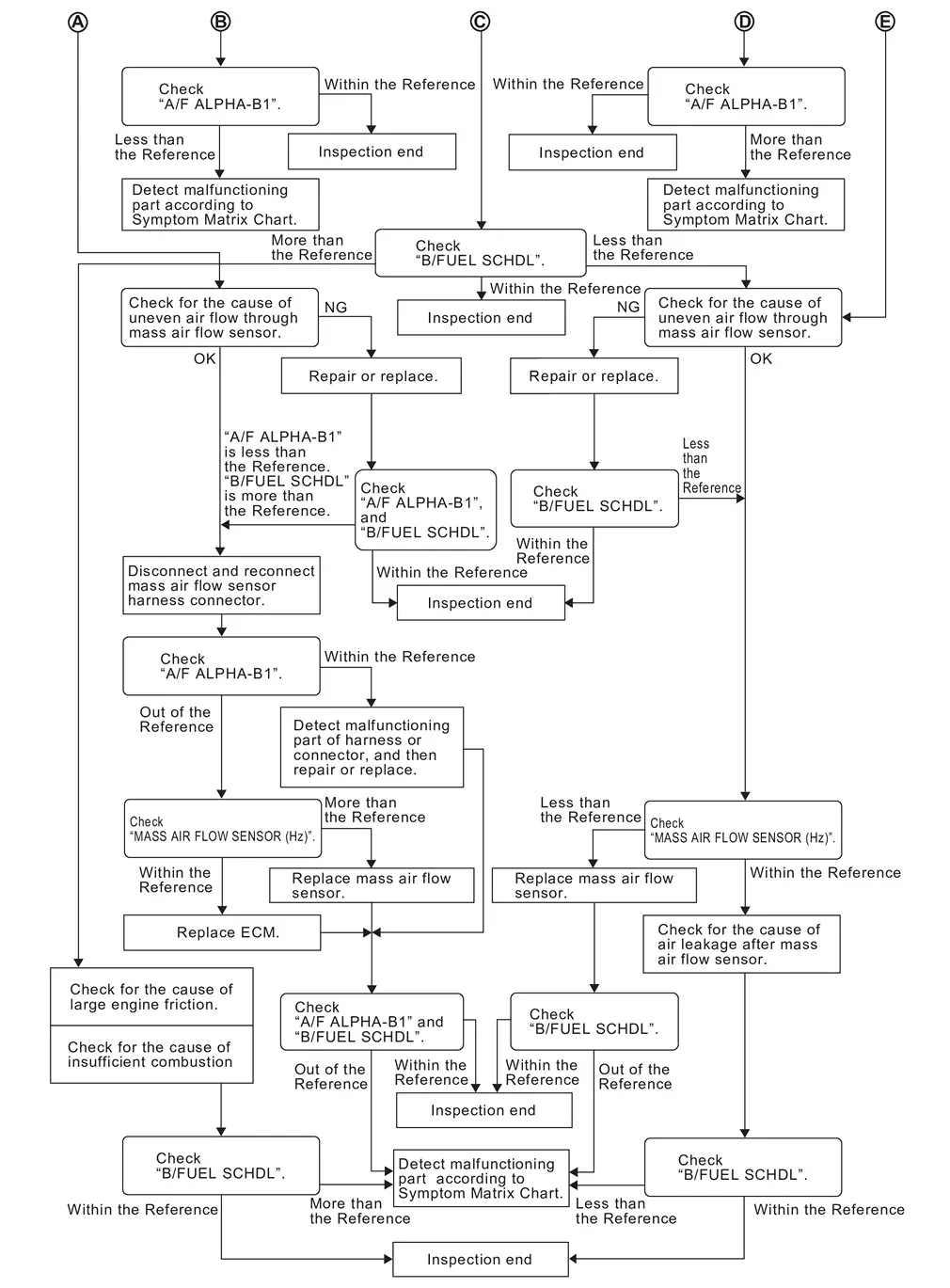
DISCONNECT AND RECONNECT ECM HARNESS CONNECTOR
-
Stop the engine.
-
Disconnect ECM harness connector. Check pin terminal and connector for damage, and then reconnect it.
>>
GO TO 16.
CHECK “A/F ALPHA-B1” AND “A/F ALPHA-B2”
 With CONSULT
-
Start engine.
-
Select “A/F ALPHA-B1” and “A/F ALPHA-B2” at “Reference” of “Data Monitor” mode, and make sure that the indication is within the Reference.
Is the measurement value within the Reference?
YES>>
INSPECTION END
NO>>
Detect malfunctioning part according to Symptom Table.
CHECK “B/FUEL SCHDL”
 With CONSULT
Select “B/FUEL SCHDL” at “Reference” of “Data Monitor” mode, and make sure that the indication is within the Reference.
Is the measurement value within the Reference?
YES>>
INSPECTION END
NO-1>>
More than the Reference: GO TO 18.
NO-2>>
Less than the Reference: GO TO 25.
DETECT MALFUNCTIONING PART
-
Check for the cause of large engine friction. Refer to the following.
-
Engine oil level is too high
-
Engine oil viscosity
-
Belt tension of power steering, alternator, A/C compressor, etc. is excessive
-
Noise from engine
-
Noise from transmission, etc.
-
-
Check for the cause of insufficient combustion. Refer to the following.
-
Valve clearance malfunction
-
Intake valve timing control function malfunction
-
Camshaft sprocket installation malfunction, etc.
-
>>
Repair or replace malfunctioning part, and then GO TO 30.
CHECK INTAKE SYSTEM
Check for the cause of uneven air flow through mass air flow sensor. Refer to the following.
-
Crushed air ducts
-
Malfunctioning seal of air cleaner element
-
Uneven dirt of air cleaner element
-
Improper specification of intake air system
Is the inspection result normal?
YES>>
GO TO 21.
NO>>
Repair or replace malfunctioning part, and then GO TO 20.
CHECK “A/F ALPHA-B1”, “A/F ALPHA-B2”, AND “B/FUEL SCHDL”
 With CONSULT
Select “A/F ALPHA-B1”, “A/F ALPHA-B2”, and “B/FUEL SCHDL” at “Reference” of “Data Monitor” mode, and make sure that the indication is within the Reference.
Is the measurement value within the Reference?
YES>>
INSPECTION END
NO>>
“B/FUEL SCHDL” is more, “A/F ALPHA-B1”, “A/F ALPHA-B2” are less than the Reference: GO TO 21.
DISCONNECT AND RECONNECT MASS AIR FLOW SENSOR HARNESS CONNECTOR
-
Stop the engine.
-
Disconnect mass air flow sensor harness connector. Check pin terminal and connector for damage and then reconnect it again.
>>
GO TO 22.
CHECK “A/F ALPHA-B1” AND “A/F ALPHA-B2”
 With CONSULT
-
Start engine.
-
Select “A/F ALPHA-B1” and “A/F ALPHA-B2” at “Reference” of “Data Monitor” mode, and make sure that the indication is within the Reference.
Is the measurement value within the Reference?
YES>>
Detect malfunctioning part of mass air flow sensor circuit and repair it. Refer to Diagnosis Procedure. Then GO TO 29.
NO>>
GO TO 23.
CHECK “MASS AIR FLOW SENSOR (Hz)”
 With CONSULT
Select “MASS AIR FLOW SENSOR (Hz)” at “Reference” of “Data Monitor” mode, and make sure that the indication is within the Reference.
Is the measurement value within the Reference?
YES>>
GO TO 24.
NO>>
More than the Reference: Replace malfunctioning mass air flow sensor, and then GO TO 29.
REPLACE ECM
-
Replace ECM. Refer to Removal and Installation.
-
Proceed to Description.
>>
GO TO 29.
CHECK INTAKE SYSTEM
Check for the cause of uneven air flow through mass air flow sensor. Refer to the following.
-
Crushed air ducts
-
Malfunctioning seal in air cleaner element
-
Uneven dirt in air cleaner element
-
Improper specification in intake air system
Is the inspection result normal?
YES>>
GO TO 27.
NO>>
Repair or replace malfunctioning part, and then GO TO 26.
CHECK “B/FUEL SCHDL”
 With CONSULT
Select “B/FUEL SCHDL” at “Reference” of “Data Monitor” mode, and make sure that the indication is within the Reference.
Is the measurement value within the Reference?
YES>>
INSPECTION END
NO>>
Less than the Reference: GO TO 27.
CHECK “MASS AIR FLOW SENSOR (Hz)”
 With CONSULT
Select “MASS AIR FLOW SENSOR (Hz)” at “Reference” of “Data Monitor” mode, and make sure that the indication is within the Reference.
Is the measurement value within the Reference?
YES>>
GO TO 28.
NO>>
Less than the Reference: Replace malfunctioning mass air flow sensor, and then GO TO 30.
CHECK INTAKE SYSTEM
Check for the cause of air leak after the mass air flow sensor. Refer to the following.
-
Disconnection, looseness, and cracks in air duct
-
Looseness of oil filler cap
-
Disconnection of oil level gauge
-
Open stuck, breakage, hose disconnection, or cracks in PCV valve
-
Disconnection or cracks in EVAP purge hose, stuck open EVAP canister purge volume control solenoid valve
-
Malfunctioning seal in rocker cover gasket
-
Disconnection, looseness, or cracks in hoses, such as a vacuum hose, connecting to intake air system parts
-
Malfunctioning seal in intake air system, etc.
>>
GO TO 30.
CHECK “A/F ALPHA-B1”, “A/F ALPHA-B2”, AND “B/FUEL SCHDL”
 With CONSULT
Select “A/F ALPHA-B1”, “A/F ALPHA-B2”, and “B/FUEL SCHDL” at “Reference” of “Data Monitor” mode, and make sure that the indication is within the Reference.
Is the measurement value within the Reference?
YES>>
INSPECTION END
NO>>
Detect malfunctioning part according to Symptom Table.
CHECK “B/FUEL SCHDL”
 With CONSULT
Select “B/FUEL SCHDL” at “Reference” of “Data Monitor” mode, and make sure that the indication is within the Reference.
Is the measurement value within the Reference?
YES>>
INSPECTION END
NO>>
Detect malfunctioning part according to Symptom Table.
Power Supply and Ground Circuit Nissan Pathfinder 2022
Ecm Diagnosis Procedure
CHECK FUSE
-
Turn ignition switch OFF.
-
Check that the following fuse is not blowing.
Location Fuse No. Capacity IPDM E/R #79 15A #81 15A Fuse, fusible link and relay box #87 15A
Is the fuse blown (open)?
YES>>
Replace the fuse after repairing the applicable circuit.
NO>>
GO TO 2.
CHECK GROUND CONNECTION
Check ground connection E9. Refer to Ground Inspection in Circuit Inspection.
Is the inspection result normal?
YES>>
GO TO 3.
NO>>
Repair or replace error-detected parts.
CHECK ECM GROUND CIRCUIT
-
Disconnect ECM harness connectors.
-
Check the continuity between ECM harness connector and ground.
ECM — Continuity Connector Terminal F78 3 Ground Existed F79 87 E32 199 201 204 -
Also check harness for short to power.
Is the inspection result normal?
YES>>
GO TO 4.
NO>>
Repair or replace error-detected parts.
CHECK IGNITION SWITCH SIGNAL
Check the voltage between ECM harness connectors as follows.
| ECM | Condition | Voltage | ||
|---|---|---|---|---|
| Connector | + | − | ||
| Terminal | ||||
| E32 | 185 | 204 | Ignition switch: ON | Battery voltage |
| Ignition switch: OFF | 0 V | |||
Is the inspection result normal?
YES>>
GO TO 6.
NO>>
GO TO 5.
CHECK IGNITION SWITCH SIGNAL CIRCUIT
-
Turn ignition switch OFF.
-
Disconnect ECM harness connectors.
-
Disconnect IPDM E/R harness connector.
-
Check the continuity between IPDM E/R harness connector and ECM harness connector.
IPDM E/R ECM Continuity Connector Terminal Connector Terminal E121 43 E32 185 Existed -
Also check harness for short to ground and short to power.
Is the inspection result normal?
YES>>
Perform trouble diagnosis for power supply circuit.
NO>>
Repair or replace error-detected parts.
CHECK ECM POWER SUPPLY
-
Reconnect ECM harness connectors.
-
Check the voltage between ECM harness connector terminals as follows.
ECM Condition Voltage Connector + − Terminal E32 197 204 Ignition switch: ON Battery voltage -
Ignition switch: OFF
-
More than a few seconds after turning ignition switch OFF
0 V -
Is the inspection result normal?
YES>>
GO TO 11.
NO>>
GO TO 7.
CHECK ECM POWER SUPPLY CIRCUIT
-
Turn ignition switch OFF.
-
Disconnect ECM harness connectors.
-
Disconnect IPDM E/R harness connector.
-
Check the continuity between IPDM E/R harness connector and ECM harness connector.
IPDM E/R ECM Continuity Connector Terminal Connector Terminal F24 73 E32 197 Existed -
Also check harness for short to ground and short to power.
Is the inspection result normal?
YES>>
GO TO 8.
NO>>
Repair or replace error-detected parts.
CHECK ECM RELAY CONTROL SIGNAL
-
Reconnect ECM harness connectors.
-
Reconnect IPDM E/R harness connectors.
-
Turn ignition switch ON.
-
Turn ignition switch OFF and wait at least 10 seconds.
-
Check the voltage between ECM harness connectors as follows.
ECM Condition Voltage + − Connector Terminal Connector Terminal F79 140 E32 204 -
Ignition switch: OFF
-
A few seconds after turning ignition switch OFF
0 − 1.0 V -
Ignition switch: OFF
-
More than a few seconds after turning ignition switch OFF
Battery voltage -
Is the inspection result normal?
YES>>
GO TO 10.
NO>>
GO TO 9.
CHECK ECM RELAY CONTROL SIGNAL CIRCUIT
-
Disconnect ECM harness connectors.
-
Disconnect IPDM E/R harness connector.
-
Check the continuity between IPDM E/R harness connector and ECM harness connector.
IPDM E/R ECM Continuity Connector Terminal Connector Terminal E78 93 F79 140 Existed -
Also check harness for short to ground and short to power.
Is the inspection result normal?
YES>>
GO TO 10.
NO>>
Repair or replace error-detected parts.
CHECK POWER SUPPLY CIRCUIT
Perform trouble diagnosis for power supply circuit.
Is the inspection result normal?
YES>>
Replace IPDM E/R. Refer to Removal and Installation.
NO>>
Repair or replace error-detected parts.
CHECK ECM POWER SUPPLY (BACK-UP)
-
Turn ignition switch OFF.
-
Check the voltage between ECM harness connectors as follows.
ECM Condition Voltage + − Connector Terminal Connector Terminal F79 170 E32 204 Ignition switch: OFF Battery voltage
Is the inspection result normal?
YES>>
Check intermittent incident. Refer to Intermittent Incident.
NO>>
Repair or replace error-detected parts.
Electric Intake Valve Timing Control Module Diagnosis Procedure
CHECK FUSE
-
Turn ignition switch OFF.
-
Check that the following fuse is not blowing.
Location Fuse No. Capacity IPDM E/R #81 15A
Is the fuse blown (open)?
YES>>
Replace the fuse after repairing the applicable circuit.
NO>>
GO TO 2.
CHECK FUSIBLE LINK
Check that the following fusible link is not blowing.
| Fusible link No. | Capacity |
|---|---|
| #K | 50A |
| #I | 50A |
Is the fusible link blown (open)?
YES>>
Replace the fusible link after repairing the applicable circuit.
NO>>
GO TO 3.
CHECK GROUND CONNECTION
Check ground connection E9. Refer to Ground Inspection in Circuit Inspection.
Is the inspection result normal?
YES>>
GO TO 4.
NO>>
Repair or replace error-detected parts.
CHECK ELECTRIC INTAKE VALVE TIMING CONTROL MODULE GROUND CIRCUIT
-
Disconnect electric intake valve timing control module harness connectors.
-
Check the continuity between electric intake valve timing control module harness connector and ground.
Electric intake valve timing control module — Continuity Connector Terminal E11 3 Ground Existed -
Also check harness for short to power.
Is the inspection result normal?
YES>>
GO TO 5.
NO>>
Repair or replace error-detected parts.
CHECK ELECTRIC INTAKE VALVE TIMING CONTROL MODULE POWER SUPPLY
-
Reconnect electric intake valve timing control module harness connectors.
-
Check the voltage between electric intake valve timing control module harness connector terminals as follows.
Electric intake valve timing control module Voltage Connector + − Terminal E11 1 3 Battery voltage 2
Is the inspection result normal?
YES>>
GO TO 6.
NO>>
Perform trouble diagnosis for power supply circuit.
CHECK IGNITION SWITCH SIGNAL
Check the voltage between electric intake valve timing control module harness connectors as follows.
| Electric intake valve timing control module | Condition | Voltage | |||
|---|---|---|---|---|---|
| + | − | ||||
| Connector | Terminal | Connector | Terminal | ||
| F99 | 95 | E11 | 3 | Ignition switch: ON | Battery voltage |
| Ignition switch: OFF | 0 V | ||||
Is the inspection result normal?
YES>>
Check intermittent incident. Refer to Intermittent Incident.
NO>>
GO TO 7.
CHECK IGNITION SWITCH SIGNAL
-
Turn ignition switch OFF.
-
Disconnect electric intake valve timing control module harness connectors.
-
Disconnect IPDM E/R harness connector.
-
Check the continuity between IPDM E/R harness connector and electric intake valve timing control module harness connector.
IPDM E/R Electric intake valve timing control module Continuity Connector Terminal Connector Terminal E121 43 F99 95 Existed -
Also check harness for short to power and short to ground.
Is the inspection result normal?
YES>>
Perform trouble diagnosis for power supply circuit.
NO>>
Repair or replace error-detected parts.
Fuel Pump Control Module (fpcm) Diagnosis Procedure
CHECK FUSE
-
Turn ignition switch OFF.
-
Check that the following fuse is not blowing.
Location Fuse No. Capacity IPDM E/R #85 20A
Is the fuse blown (open)?
YES>>
Replace the fuse after repairing the applicable circuit.
NO>>
GO TO 2.
CHECK GROUND CONNECTION
Check ground connection B19. Refer to Ground Inspection in Circuit Inspection.
Is the inspection result normal?
YES>>
GO TO 3.
NO>>
Repair or replace ground connection.
CHECK FPCM GROUND CIRCUIT FOR OPEN AND SHORT
-
Disconnect FPCM harness connectors.
-
Check the continuity between FPCM harness connector and ground.
FPCM — Continuity Connector Terminal B58 4 Ground Existed -
Also check harness for short to power.
Is the inspection result normal?
YES>>
GO TO 4.
NO>>
Repair or replace error-detected parts.
CHECK FPCM POWER SUPPLY
-
Turn ignition switch ON.
-
Check the voltage between FPCM harness connector terminals.
FPCM Voltage Connector + − Terminal B58 1 4 Battery voltage
Is the inspection result normal?
YES>>
Check intermittent incident. Refer to Intermittent Incident.
NO>>
GO TO 5.
CHECK FPCM POWER SUPPLY CIRCUIT
-
Turn ignition switch OFF.
-
Disconnect FPCM harness connectors.
-
Disconnect IPDM E/R harness connectors.
-
Check the continuity between IPDM E/R harness connector and FPCM harness connector.
IPDM E/R FPCM Continuity Connector Terminal Connector Terminal E121 46 B58 1 Existed -
Also check harness for short to power and short to ground.
Is the inspection result normal?
YES>>
GO TO 6.
NO>>
Repair or replace error-detected parts.
CHECK FUEL PUMP RELAY SIGNAL
-
Reconnect IPDM E/R harness connectors.
-
Turn ignition switch ON.
-
Check the voltage between ECM harness connectors.
ECM Voltage + − Connector Terminal Connector Terminal F78 84 E32 204 0 − 1.0 V
Is the inspection result normal?
YES>>
GO TO 8.
NO>>
GO TO 7.
CHECK FUEL PUMP RELAY SIGNAL CIRCUIT
-
Turn ignition switch OFF.
-
Disconnect ECM harness connectors.
-
Disconnect IPDM E/R harness connectors.
-
Check the continuity between IPDM E/R harness connector and ECM harness connector.
IPDM E/R ECM Continuity Connector Terminal Connector Terminal F24 76 F78 84 Existed -
Also check harness for short to power and short to ground.
Is the inspection result normal?
YES>>
GO TO 8.
NO>>
Repair or replace error-detected parts.
CHECK POWER SUPPLY CIRCUIT
Perform trouble diagnosis for power supply circuit.
Is the inspection result normal?
YES>>
Replace IPDM E/R. Refer to Removal and Installation.
NO>>
Repair or replace error-detected parts.

Nissan Pathfinder (R53) 2022-2026 Service Manual
Dtc/circuit Diagnosis
- Trouble Diagnosis - Specification Value
- Power Supply and Ground Circuit
- C053c Wheel Speed Sensor
- U0101 Can Comm Circuit
- U0122 Vehicle Dynamics Control Module
- U012e Engine Communication
- U0155 Can Communication (ipc)
- U0284 Active Grille Shutter
- U1000 Can Communication Circuit
- U1040 Eng Comm Circuit
- U1327 Mac Key
- U2118 Can Comm Circuit
- U2141 Can Comm Circuit
- P0011 Intake Valve Timing Control
- P0014 Evt Control
- P0030 A/f Sensor 1 Heater
- P0078 Evt Control Solenoid Valve
- P0087 Frp Control System ++
- P00d2 Ho2s2 Heater
- P00fe Evap Control System
- P0101 Maf Sensor
- P0107 Barometric Pressure Sensor
- P0111 Iat Sensor
- P0116 Engine Coolant Temperature Sensor
- P0122 Tp Sensor
- P0127 Iat Sensor
- P0128 Thermostat Function
- P0130 A/f Sensor 1
- P0138 Ho2s2
- P0171 Fuel Injection System Function
- P0181 Ftt Sensor
- P01f0 Engine Coolant Temperature
- P025b Fuel Pump Module a
- P026b Injection Timing
- P0300 Misfire
- P0315 Crankshaft Position
- P0326 Knock Sensor
- P0327 Ks
- P0335 Crankshaft Position Sensor
- P0340 Cmp Sensor
- P0365 Exhaust Camshaft Position Sensor
- P0385 Ckp Sensor 2
- P0420 Three Way Catalyst Function
- P0441 Evap Control System
- P0443 Evap Canister Purge Volume Control Solenoid Valve
- P0447 Evap Canister Vent Control Valve
- P0450 Evap Control System Pressure Sensor
- P0461 Fuel Level Sensor
- P0500 Vss
- P0506 Isc System
- P050a Cold Start Control
- P0520 Eop Sensor
- P0524 Engine Oil Pressure
- P0532 A/c Refrigerant Pressure Sensor
- P055f Engine Oil Pressure
- P0573 Brake Pedal Switch a
- P059f Active Grille Shutter
- P0606 Ecm
- P0611 Ecm Protection
- P062b Ecm
- P062f Control Module
- P0643 Sensor Power Supply
- P064d Ecm
- P06da Engine Oil Pressure Control Solenoid Valve
- P06dd Variable Oil Pressure Valve
- P06e6 Internal Control Module
- P0719 Brake Pedal Switch B
- P0850 Pnp Switch
- P1140 Intake Camshaft Position Sensor
- P1148 Closed Loop Control
- P1197 Out of Gas
- P119a Fuel Rail Pressure Sensor
- P1217 Engine Over Temperature
- P1220 Fuel Pump Control Module (fpcm)
- P1225 Tp Sensor
- P12a9 Hvac Communication
- P1526 Ascd System
- P155b Energy Management Control
- P155d Generator
- P1564 Ascd Steering Switch
- P1568 Icc Function
- P1572 Brake Pedal Position Switch
- P1574 Ascd Vehicle Speed Sensor
- P1575 Brake Switch
- P159f Active Grille Shutter
- P1603 Ecm
- P161d Immobilizer
- P1650 Starter Motor Relay 2
- P1800 Vias Control Solenoid Valve 1
- P1805 Stop Lamp Switch
- P1a10 Ecm Initial Learning Incomplete
- P2100 Throttle Control Motor Relay
- P2101 Electric Throttle Control Function
- P2118 Throttle Control Motor
- P2119 Electric Throttle Control Actuator
- P2122 App Sensor
- P2138 App Sensor
- P219a Air Fuel Ratio
- P2297 Air Fuel Ratio Sensor 1
- P25df Electric Intake Valve Timing Control Motor
- P2610 Ecm Internal Timer
- P2b96 Injection Pulse
- P34ac Electric Intake Valve Timing Control Actuator
- Active Grille Shutter
- Ascd Indicator
- Cooling Fan
- Crankshaft Position Sensor 2
- Electrical Load Signal
- Electronic Controlled Engine Mount
- Fuel Injector
- Fuel Pump
- High Pressure Fuel Pump
- Ignition Signal
- Information Display (ascd)
- Malfunction Indicator Lamp
- Mass Air Flow Sensor
- On Board Refueling Vapor Recovery (orvr)
- Refrigerant Pressure Sensor
- Sensor Power Supply 2 Circuit
- Variable Induction Air System
Contact Us
Nissan Pathfinder Info Center
Email: info@nipathfinder.com
Phone: +1 (800) 123-4567
Address: 123 Pathfinder Blvd, Nashville, TN 37214, USA
Working Hours: Mon–Fri, 9:00 AM – 5:00 PM (EST)
