Nissan Pathfinder: Dtc/circuit Diagnosis (P0532 A/c Refrigerant Pressure Sensor ... P064d Ecm)
- P0532 A/c Refrigerant Pressure Sensor
- P055f Engine Oil Pressure
- P0573 Brake Pedal Switch a
- P059f Active Grille Shutter
- P0606 Ecm
- P0611 Ecm Protection
- P062b Ecm
- P062f Control Module
- P0643 Sensor Power Supply
- P064d Ecm
P0532 A/c Refrigerant Pressure Sensor Nissan Pathfinder 2026
DTC Description
DTC DETECTION LOGIC
| DTC |
CONSULT screen terms (Trouble diagnosis name) | DTC detecting condition | ||
|---|---|---|---|---|
| P0532 | 00 |
REFRIGERANT PRESS SENSOR A (A/C refrigerant pressure sensor A circuit low) |
Diagnosis condition |
|
| Signal (terminal) | Refrigerant pressure sensor signal | |||
| Threshold | ECM detects that input signal from the refrigerant pressure sensor is out of the specified range. | |||
| Diagnosis delay time | 5 seconds or more | |||
POSSIBLE CAUSE
-
Harness or connectors
-
Refrigerant pressure sensor
FAIL-SAFE
Not applicable
Confirmation Procedure
PRECONDITIONING-1
If DTC Confirmation Procedure has been previously conducted, always perform the following procedure before conducting the next test.
-
Turn ignition switch OFF and wait at least 10 seconds.
-
Turn ignition switch ON.
-
Turn ignition switch OFF and wait at least 10 seconds.
TESTING CONDITION:
Before performing the following procedure, confirm that battery voltage is 11 V or more under ignition switch OFF condition.
>>
GO TO 2.
PRECONDITIONING-2
Check the following conditions:
| Ambient temperature | 0°C (32°F) or more |
Is the condition satisfied?
YES>>GO TO 3.
NO>>-
Satisfy the condition.
-
GO TO 3.
PERFORM COMPONENT FUNCTION CHECK
Perform component function check. Refer to Component Function Check.
Is the inspection result normal?
YES>>GO TO 4.
NO>>Proceed to DTC Diagnosis Procedure.
PERFORM DTC CONFIRMATION PROCEDURE
-
Start engine and warm it up to normal operating temperature.
-
Hold Nissan Pathfinder vehicle speed at more than 40 km/h (25 MPH) for 180 consecutive seconds.
CAUTION:
Always drive Nissan Pathfinder vehicle at a safe speed.
-
Check 1st trip DTC.
Is 1st trip DTC detected?
YES>>Proceed to DTC Diagnosis Procedure.
NO>>INSPECTION END
DTC Diagnosis Procedure
CHECK REFRIGERANT PRESSURE SENSOR
Refer to Diagnosis Procedure.
Is the inspection result normal?
YES>>INSPECTION END
NO>>Replace refrigerant pressure sensor.
P055f Engine Oil Pressure Nissan Pathfinder
DTC Description
DTC DETECTION LOGIC
| DTC |
CONSULT screen terms (Trouble diagnosis content) |
DTC detection condition | |
| P055F |
Engine oil pressure (Engine oil pressure out of range) |
Diagnosis condition |
|
| Signal (terminal) | Engine oil pressure sensor signal | ||
| Threshold | When the engine oil pressure is higher than normal value at stop engine. | ||
| Diagnosis delay time | 3.5 seconds | ||
POSSIBLE CAUSE
-
Harness or connectors (Engine oil pressure sensor, engine oil temperature sensor or crankshaft position sensor circuit is open or shorted.)
-
Engine oil pressure sensor
-
Engine oil temperature sensor
-
Engine oil pressure control solenoid valve
-
Crankshaft position sensor
-
Oil pump
-
Clogging in oil line
-
Amount of engine oil
FAIL-SAFE
Not applicable
DTC CONFIRMATION PROCEDURE
PRECONDITIONING
If DTC Confirmation Procedure has been previously conducted, always perform the following procedure before conducting the next test.
-
Turn ignition switch OFF and wait at least 10 seconds.
-
Turn ignition switch ON.
-
Turn ignition switch OFF and wait at least 10 seconds.
>>
GO TO 2.
PERFORM DTC CONFIRMATION PROCEDURE
-
Turn ignition switch ON and wait at least 30 seconds.
-
Check 1st trip DTC.
Is 1st trip DTC detected?
YES>>Refer to DTC Diagnosis Procedure.
NO-1>>To check malfunction symptom before repair: Refer to Intermittent Incident.
NO-2>>Confirmation after repair: INSPECTION END
DTC Diagnosis Procedure
CHECK DTC PRIORITY
If DTC P055F is displayed with other DTC, first perform the trouble diagnosis for other DTC.
Is other DTC detected?
YES>>Perform diagnosis of applicable. Refer to DTC Index.
NO>>GO TO 2.
CHECK HARNESS CONNECTOR
-
Disconnect following sensors harness connector and ECM harness connector.
-
Engine oil pressure sensor
-
Engine oil temperature sensor
-
Crankshaft position sensor
-
-
Connect following sensors harness connector and ECM harness connector.
-
Engine oil pressure sensor
-
Engine oil temperature sensor
-
Crankshaft position sensor
-
-
Perform DTC Confirmation Procedure. Refer to DTC Description.
Is DTC detected?
YES>>GO TO 3.
NO>>INSPECTION END
CHECK ENGINE OIL LEVEL AND LEAKAGE
-
Turn ignition switch OFF.
-
Check engine oil level and leakage. Refer to Inspection.
Is the inspection result normal?
YES>>GO TO 4.
NO>>Repair or replace error-detected parts.
CHECK OIL PUMP
Visually check oil pump and listen to operation sound.
Is the inspection result normal?
YES>>GO TO 5.
NO>>Repair or replace error-detected parts.
CHECK ENGINE OIL PRESSURE
 With CONSULT
-
Turn ignition switch ON.
-
On CONSULT screen, select “ENGINE”>>“Data Monitor”.
-
Start the engine and check that “EOP SENSOR” changes, according to engine speeds.
Monitor item Condition Value EOP SENSOR -
Engine: After warming up
-
Selector lever: P or N
-
Air conditioner switch: OFF
-
No load
Idle 1.570 – 1.900 V 2,000 rpm 1.610 – 2.120 V -
 Without CONSULT
Check engine oil pressure. Refer to Inspection.
Is the inspection result normal?
YES>>INSPECTION END
NO>>Change engine oil. Refer to Draining and Refilling.
P0573 Brake Pedal Switch a Nissan Pathfinder
DTC Description
DTC DETECTION LOGIC
| DTC |
CONSULT screen terms (Trouble diagnosis content) |
DTC detection condition | ||
| P0573 | 00 |
Brake pedal switch A (Brake Switch "A" Circuit High) |
Diagnosis condition |
|
| Signal (terminal) | Brake pedal position switch signal | |||
| Threshold | Brake pedal position switch is released until 2 seconds have passed after the Nissan Pathfinder vehicle has stopped when the diagnosis condition is established. Malfunction is confirmed when the above condition is established 5 times. | |||
| Diagnosis delay time | — | |||
POSSIBLE CAUSE
-
Harness or connectors
(Brake pedal position switch circuit is close.)
-
Brake pedal position switch
FAIL-SAFE
Not applicable
CONFIRMATION PROCEDURE
CHECK DTC PRIORITY
If DTC P0573 is displayed with DTC P0605, first perform the confirmation procedure (trouble diagnosis) for DTC P0605.
Is DTC P0605 detected?
YES>>Perform diagnosis for P0605. Refer to Diagnosis Procedure.
NO>>GO TO 2.
PRECONDITIONING
If DTC Confirmation Procedure has been previously conducted, always perform the following procedure before conducting the next test.
-
Turn ignition switch OFF and wait at least 10 seconds.
-
Turn ignition switch ON.
-
Turn ignition switch OFF and wait at least 10 seconds.
TEST CONDITION:
Before performing the following procedure, confirm that battery voltage is more than 11 V at ignition switch ON.
>>
GO TO 3.
PERFORM DTC CONFIRMATION PROCEDURE
-
Turn ignition switch ON and wait at least 2 seconds.
-
Repeat the following step 5 times.
-
Drive the Nissan Pathfinder vehicle and accelerate to 48 km/h (30 MPH).
-
Decelerate from 48 km/h (30 MPH) to 0 km/h (0 MPH) within 7 seconds.
-
Stop the Nissan Pathfinder vehicle for 2 seconds or more.
CAUTION:
Always drive vehicle at a safe speed.
 NOTE:
NOTE:
This procedure may be conducted with the drive wheels lifted in the shop or by driving the Nissan Pathfinder vehicle. If a road test is expected to be easier, it is unnecessary to lift the vehicle.
-
-
Check DTC.
Is DTC P0573 detected?
YES>>Refer to DTC Diagnosis Procedure.
NO-1>>To check malfunction symptom before repair: Refer to Intermittent Incident.
NO-2>>Confirmation after repair: INSPECTION END
DTC Diagnosis Procedure
CHECK DTC PRIORITY
If DTC P1572 is displayed with other DTC, first perform the trouble diagnosis for other DTC.
Is applicable DTC detected?
YES>>Perform diagnosis of applicable. Refer to DTC Index.
NO>>GO TO 2.
CHECK OVERALL FUNCTION-1
 With CONSULT
-
Turn ignition switch ON.
-
Select “BRAKE SW1” and “BRAKE SW2” in “DATA MONITOR” mode of “ENGINE” using CONSULT.
-
Check “BRAKE SW1” and “BRAKE SW2” indication as per the following conditions.
Monitor item Condition Indication BRAKE SW1 Brake pedal Slightly depressed OFF Fully released ON BRAKE SW2 Brake pedal Slightly depressed ON Fully released OFF
 Without CONSULT
-
Turn ignition switch ON.
-
Check the voltage between ECM harness connector terminals as per the following.
ECM Condition Voltage
(Approx.)Connector + – Terminal E32 192 204 Brake pedal Slightly depressed 0 V Fully released Battery voltage
Is the inspection result normal?
YES>>GO TO 3.
NO>>GO TO 4.
CHECK STOP LAMP SWITCH POWER SUPPLY CIRCUIT
-
Turn ignition switch OFF.
-
Disconnect stop lamp switch harness connector.
-
Check the voltage between stop lamp switch harness connector and ground.
+ − Voltage Stop lamp switch Connector Terminal E38 1 Ground Battery voltage
Is the inspection result normal?
YES>>GO TO 4.
NO>>Perform the trouble diagnosis for power supply circuit.
CHECK STOP LAMP SWITCH
Check the stop lamp switch. Refer toComponent Inspection .
Is the inspection result normal?
YES>>GO TO 5.
NO>>Replace stop lamp switch. Refer to Exploded View.
CHECK STOP LAMP SWITCH SIGNAL CIRCUIT
-
Disconnect BCM harness connector.
-
Check the continuity between stop lamp switch harness connector and ECM harness connector.
+ − Continuity Stop lamp switch BCM Connector Terminal Connector Terminal E38 2 M80 110 Existed -
Also check harness for short to ground and to power.
Is the inspection result normal?
YES>>Check intermittent incident. Refer to Intermittent Incident.
NO>>GO TO 6.
REPLACE ECM
Replace ECM. Refer to Removal and Installation.
>>
INSPECTION END
P059f Active Grille Shutter Nissan Pathfinder SUV
DTC Description
DTC DETECTION LOGIC
Active grille shutter normally stops within zone
 which is defined by zone
 (90°±10°).
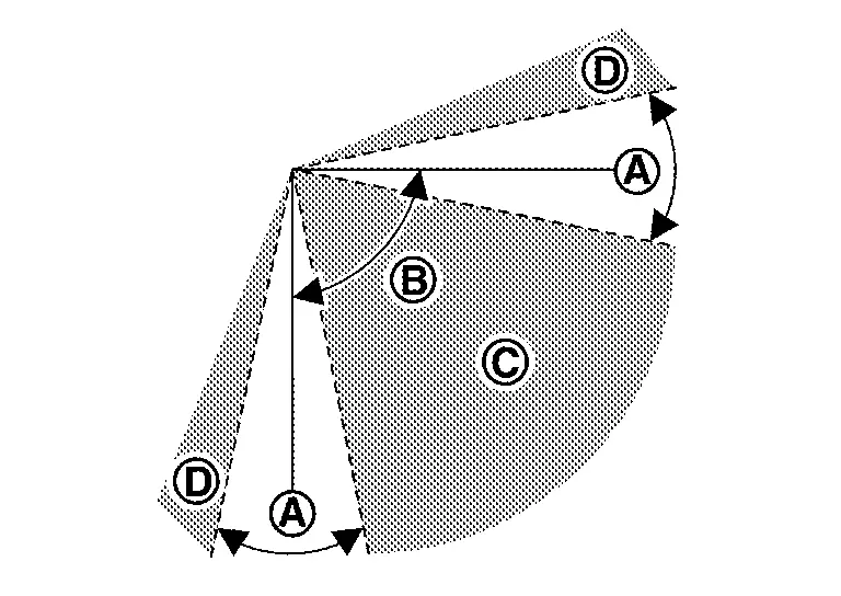
If the active grille shutter stops within zone
 stuck error is detected, and if the active grille shutter stops at position beyond zone
 overrun error is detected.
| DTC |
CONSULT screen terms (Trouble diagnosis content) |
DTC detection condition | ||
| P059F | 00 |
ACTIVE GRILLE AIR SHUTTER A (Active grille air shutter A performance/stuck off) |
Diagnosis condition | — |
| Signal (terminal) | Active grille shutter communication signal | |||
| Threshold | Detects the malfunction of initial position learning or operational malfunctions for specified times. | |||
| Diagnosis delay time | — | |||
POSSIBLE CAUSE
-
Harness or connectors
(Active grille shutter circuit is open or shorted.)
-
Active grille shutter
-
Foreign objects interferes with active grille shutter
FAIL-SAFE
Not applicable
DTC Confirmation Procedure
CHECK DTC PRIORITY
If DTC P059F is displayed with other DTC, first perform the trouble diagnosis for other DTC.
Is applicable DTC detected?
YES>>Perform diagnosis of applicable. Refer to DTC Index.
NO>>GO TO 2.
PERFORM DIAGNOSIS PROCEDURE
 NOTE:
NOTE:
Since this DTC is difficult to be confirmed, perform diagnosis procedure to judge the normality.
>>
Refer to DTC Diagnosis Procedure.
DTC Diagnosis Procedure
CHECK DTC PRIORITY
If DTC P059F is displayed with other DTC, first perform the trouble diagnosis for other DTC.
Is applicable DTC detected?
YES>>Perform diagnosis of applicable. Refer to DTC Index.
NO>>GO TO 2.
CHECK ACTIVE GRILL SHUTTER
-
Turn ignition switch OFF.
-
Check if any foreign objects interferes with active grille shutter.
-
Check the installation condition of active grille shutter.
Is the inspection result normal?
YES>>GO TO 3.
NO>>Repair or replace the error-detected parts.
CHECK ACTIVE GRILLE SHUTTER POWER SUPPLY
-
Disconnect active grille shutter harness connector.
-
Check the voltage between active grille shutter harness connector and ground as follows.
+ − Condition Voltage
(Approx.)Active grille shutter Connector Terminal E202 1 Ground Ignition switch: ON Battery voltage Ignition switch: OFF 0 V
Is the inspection result normal?
YES>>GO TO 5.
NO>>GO TO 4.
CHECK ACTIVE GRILLE SHUTTER POWER SUPPLY CIRCUIT
-
Turn ignition switch OFF
-
Disconnect IPDM E/R harness connector.
-
Check the continuity between active grille shutter harness connector and IPDM E/R harness connector.
Active grille shutter IPDM E/R Continuity Connector Terminal Connector Terminal E202 1 E120 8 Existed
Is the inspection result normal?
YES>>Perform trouble diagnosis for power supply circuit.
NO>>Repair or replace the error-detected parts.
CHECK ACTIVE GRILLE SHUTTER GROUND CIRCUIT
-
Turn ignition switch OFF
-
Check the continuity between active grille shutter harness connector and ground.
Active grille shutter − Continuity Connector Terminal E202 4 Ground Existed -
Also check harness for short to ground and short to power.
Is the inspection result normal?
YES>>GO TO 6.
NO>>Repair open circuit, short to ground or short to power in harness or connectors.
CHECK ACTIVE GRILLE SHUTTER INPUT SIGNAL CIRCUIT
-
Disconnect ECM harness connector.
-
Check the continuity between ECM harness connector and active grille shutter harness connector.
| + | – | Continuity | ||
|---|---|---|---|---|
| ECM | Active grille shutter | |||
| Connector | Terminal | Connector | Terminal | |
| F79 | 167 | E202 | 3 | Existed |
Is the inspection result normal?
YES>>GO TO 7.
NO>>Repair or replace the error-detected parts.
CHECK ACTIVE GRILLE SHUTTER
Check active grille shutter. Refer to Component Inspection.
Is the inspection result normal?
YES>>INSPECTION END
NO>>Replace active grille shutter. Refer to Removal and Installation.
P0606 Ecm Nissan Pathfinder Fifth generation
DTC Description
DTC DETECTION LOGIC
| DTC |
CONSULT screen terms (Trouble diagnosis content) |
DTC detection condition | ||
| P0606 | 00 |
CONTROL MODULE (Control module processor) |
Diagnosis condition | — |
| Signal (terminal) | — | |||
| Threshold | Malfunction in ECM processor | |||
| Diagnosis delay time | — | |||
POSSIBLE CAUSE
ECM
FAIL-SAFE
| Fail safe mode | Nissan Pathfinder Vehicle behavior | |
|---|---|---|
| Device fix mode |
|
|
| Electric throttle control cancel mode | ECM stops the electric throttle control actuator control, throttle valve is maintained at a fixed opening (approx. 5 degrees) by the return spring. | |
DTC Confirmation Procedure
PRECONDITIONING
-
Turn ignition switch OFF and wait at least 10 seconds.
-
Turn ignition switch ON.
-
Turn ignition switch OFF and wait at least 10 seconds.
TESTING CONDITION:
Before performing the following procedure, confirm that battery voltage is 11 V or more with ignition switch ON.
>>
GO TO 2.
PERFORM DTC CONFIRMATION PROCEDURE-I
-
Turn ignition switch ON (engine stopped) and wait at least 10 seconds.
CAUTION:
Never start engine during this procedure.
-
Turn ignition switch OFF and wait at least 10 seconds.
-
Turn ignition switch ON.
-
Check 1st trip DTC.
Is DTC P0606 detected?
YES>>Proceed to Diagnosis Procedure.
NO>>GO TO 3.
PERFORM DTC CONFIRMATION PROCEDURE-II
-
Start engine.
-
Rev up the engine quickly to approximately 3,000 rpm under unloaded condition and completely release the accelerator pedal.
-
Let the engine idle and wait at least 10 seconds.
-
Turn ignition switch OFF and wait at least 10 seconds.
-
Turn ignition switch ON.
-
Check 1st trip DTC.
Is DTC P0606 detected?
YES>>Proceed to Diagnosis Procedure.
NO-1>>To check malfunction symptom before repair: Refer to Intermittent Incident.
NO-2>>Confirmation after repair: INSPECTION END
Diagnosis Procedure
PERFORM DTC CONFIRMATION PROCEDURE
-
Turn ignition switch ON.
-
Erase DTC.
-
Perform DTC confirmation procedure for 3 times. Refer to DTC Description.
Is the DTC P0606 displayed again?
YES>>Replace ECM. Refer to Removal and Installation.
NO>>INSPECTION END
P0611 Ecm Protection Nissan Pathfinder 2022
DTC Description
This DTC is detected when the ECM protective function is activated due to an extreme temperature increase in ECM, resulting from severe conditions such as heavy load driving.
DTC DETECTION LOGIC
| DTC |
CONSULT screen terms (Trouble diagnosis content) |
DTC detection condition | ||
| P0611 | 00 |
FIC MODULE (Fuel Injector Control Module Performance) |
Diagnosis condition | — |
| Signal (terminal) | — | |||
| Threshold | ECM overheat protection control is activated | |||
| Diagnosis delay time | — | |||
POSSIBLE CAUSE
ECM overheating
FAIL-SAFE
Not applicable
DTC CONFIRMATION PROCEDURE
PERFORM DTC CONFIRMATION PROCEDURE
This DTC is displayed as protection function history. If no malfunction is detected after the diagnosis, the customer must be informed of the activation of the protection function.
>>
Refer to DTC Diagnosis Procedure.
DTC Diagnosis Procedure
INSPECTION START
-
Perform DTC P0605 confirmation procedure. Refer to DTC Description.
-
Check 1st trip DTC.
Is the 1st trip DTC P0605 detected?
YES>>Refer to DTC Description.
NO>>Explain the customer about the activation of the protection function.
P062b Ecm Nissan Pathfinder
DTC Description
When the malfunction occurs in the fuel injector driver circuit, DTC is detected.
DTC DETECTION LOGIC
| DTC |
CONSULT screen terms (Trouble diagnosis content) |
DTC detection condition | ||
| P062B | 00 |
ECM (Internal control module fuel injector control performance) |
Diagnosis condition | Engine running at idle |
| Signal (terminal) | — | |||
| Threshold | Injector driver unit is malfunctioning | |||
| Diagnosis delay time | — | |||
POSSIBLE CAUSE
-
Harness and connectors (Injector circuit is open or shorted)
-
Battery power supply
-
ECM (injector driver unit)
-
Fuel injector relay
FAIL-SAFE
| Fail safe mode | Nissan Pathfinder Vehicle behavior | |
|---|---|---|
| Traveling control mode | Accelerator angle variation control |
ECM controls the accelerator pedal depression speed to make it slower than actual speed. This causes a drop in accelerating performance and encourages the driver to repair malfunction.
ECM does not control the accelerator pedal releasing speed. |
| Device fix mode |
|
|
| Combustion control mode | Stratified charge combustion control at starting | No stratified charge combustion at starting (cold start). |
 NOTE:
NOTE:
DTC Confirmation Procedure
PRECONDITIONING
-
Turn ignition switch OFF and wait at least 10 seconds.
-
Turn ignition switch ON.
-
Turn ignition switch OFF and wait at least 10 seconds.
TESTING CONDITION:
Before performing the following procedure, confirm that battery voltage is 11 V or more at idle.
>>
GO TO 2.
PERFORM DTC CONFIRMATION PROCEDURE
-
Start the engine and keep the engine speed at idle for 30 seconds.
-
Check 1st trip DTC.
Is DTC P062B detected?
YES>>Proceed to Diagnosis Procedure.
NO-1>>To check malfunction symptom before repair: Refer to Intermittent Incident.
NO-2>>Confirmation after repair: INSPECTION END
Diagnosis Procedure
CHECK FUEL INJECTOR DRIVER CIRCUIT
Check ECM (Injector driver unit), relay, connector and harness for error or abnormality. Refer to Component Function Check.
Is inspection result normal?
YES>>GO TO 2.
NO>>Repair or replace error-detected parts.
PERFORM DTC CONFIRMATION PROCEDURE
-
Turn ignition switch ON.
-
Erase DTC.
-
Perform DTC confirmation procedure again. Refer to DTC Description.
-
Check 1st trip DTC.
Is the DTC P062B displayed again?
YES>>Replace ECM. Refer to Removal and Installation.
NO>>INSPECTION END
P062f Control Module Nissan Pathfinder Fifth generation
DTC Description
DTC DETECTION LOGIC
| DTC |
CONSULT screen terms (Trouble diagnosis content) |
DTC detection condition | ||
| P062F | 00 |
CONTROL MODULE (Internal control module EEPROM error) |
Diagnosis condition | Ignition switch ON |
| Signal (terminal) | — | |||
| Threshold | ECM calculation is function malfunctioning | |||
| Diagnosis delay time | — | |||
POSSIBLE CAUSE
ECM
FAIL-SAFE
Not applicable
DTC Confirmation Procedure
PRECONDITIONING
If DTC Confirmation Procedure has been previously conducted, always perform the following
procedure before conducting the next test.
-
Turn ignition switch OFF and wait at least 10 seconds.
-
Turn ignition switch ON.
-
Turn ignition switch OFF and wait at least 10 seconds.
TESTING CONDITION:
Before performing the following procedure, confirm that battery voltage is between 11 V or more with ignition switch ON.
>>
GO TO 2.
PERFORM DTC CONFIRMATION PROCEDURE
-
Turn ignition switch ON and wait at least 1 second.
-
Turn ignition switch OFF and wait at least 10 seconds.
-
Repeat step 1 and 2 for 10 times.
-
Erase DTC.
-
Turn ignition switch OFF and wait at least 10 seconds.
-
Turn ignition switch ON.
-
Check the DTC.
Is DTC P062F detected?
YES>>Proceed to Diagnosis Procedure.
NO-1>>To check malfunction symptom before repair: Refer to Intermittent Incident.
NO-2>>Confirmation after repair: INSPECTION END
Diagnosis Procedure
INSPECTION START
-
Turn ignition switch ON and wait at least 1 second.
-
Turn ignition switch OFF and wait at least 10 seconds.
-
Repeat step 1 and 2 for 10 times.
-
Erase DTC.
-
Turn ignition switch OFF and wait at least 10 seconds.
-
Turn ignition switch ON.
-
Check the DTC.
Is DTC erased?
YES>>INSPECTION END
NO>>GO TO 2.
REPLACE ECM
-
Replace ECM. Refer to Removal and Installation.
-
Perform Description.
>>
INSPECTION END
P0643 Sensor Power Supply Nissan Pathfinder R53
DTC Description
ECM supplies a voltage of 5 V to some of the sensors systematically divided into 3 groups, respectively. Accordingly, when a short circuit develops in a sensor power source, a malfunction may occur simultaneously in the sensors belonging to the same group as the short-circuited sensor.
Sensor power supply 1
-
APP sensor 1
-
Crankshaft position sensor 1
-
Exhaust camshaft position sensor (bank 1)
-
Throttle position sensor
-
Mass air flow sensor
-
Intake camshaft position sensor (bank 1)
-
Engine oil pressure sensor
 NOTE:
NOTE:
If sensor power supply 1 circuit is malfunctioning, DTC P0643 is displayed.
Sensor power supply 2
-
APP sensor 2
-
Intake camshaft position sensor (bank2)
-
Refrigerant pressure sensor
-
Crankshaft position sensor 2
-
Exhaust camshaft position sensor (bank 2)
-
Fuel rail pressure sensor
Sensor power supply 3
-
EVAP control system pressure sensor
DTC DETECTION LOGIC
| DTC |
CONSULT screen terms (Trouble diagnosis content) |
DTC detection condition | ||
| P0643 | 00 |
SENSOR POWER/CIRC (Sensor power supply 1 circuit short) |
Diagnosis condition | Engine running at idle |
| Signal (terminal) | Sensor power supply 1 signal | |||
| Threshold | A voltage of power source for sensor is excessively low or high | |||
| Diagnosis delay time | — | |||
POSSIBLE CAUSE
-
Harness or connectors
-
Crankshaft position sensor 1 is shorted.
-
Exhaust camshaft position sensor (bank 1) is shorted.
-
Throttle position sensor is shorted.
-
Mass air flow sensor is shorted.
-
Accelerator pedal position sensor 1 is shorted.
-
Intake camshaft position sensor (bank 1) is shorted.
-
Engine oil pressure sensor is shorted.
-
-
Crankshaft position sensor 1
-
Exhaust camshaft position sensor (bank 1)
-
Throttle position sensor
-
Mass air flow sensor
-
Accelerator pedal position sensor 1
-
Intake camshaft position sensor (bank 1)
-
Engine oil pressure sensor
FAIL-SAFE
| Fail safe mode | Nissan Pathfinder Vehicle behavior | |
|---|---|---|
| Device fix mode |
|
|
| Electric throttle control cancel mode | ECM stops the electric throttle control actuator control, throttle valve is maintained at a fixed opening (approx. 5 degrees) by the return spring. | |
DTC Confirmation Procedure
PRECONDITIONING
TESTING CONDITION:
Before performing the following procedure, confirm that battery voltage is 11 V or more with ignition switch ON.
>>
GO TO 2.
PERFORM DTC CONFIRMATION PROCEDURE
-
Turn ignition switch ON and wait at least 10 second.
-
Turn ignition switch OFF and wait at least 10 seconds.
-
Repeat step 1 and 2 for 2 times.
-
Turn ignition switch ON.
-
Check the DTC.
Is the DTC detected?
YES>>Proceed to Diagnosis Procedure.
NO-1>>To check malfunction symptom before repair: Refer to Intermittent Incident.
NO-2>>Confirmation after repair: INSPECTION END
Diagnosis Procedure
CHECK ECM POWER SUPPLY AND GROUND CIRCUIT
Perform trouble diagnosis for ECM power supply and ground circuit. Refer to Diagnosis Procedure.
Is the inspection result normal?
YES>>GO TO 2.
NO>>Repair or replace error-detected parts.
CHECK ACCELERATOR PEDAL POSITION SENSOR 1 POWER SUPPLY CIRCUIT
-
Disconnect accelerator pedal position (APP) sensor harness connector.
-
Turn ignition switch ON.
-
Check the voltage between APP sensor harness connector and ground.
+ - Voltage
(Approx.)APP sensor Connector Terminal E31 4 Ground 5 V
Is the inspection result normal?
YES>>GO TO 5.
NO>>GO TO 3.
CHECK SENSOR POWER SUPPLY CIRCUITS
Check harness for short to power and short to ground, between the following terminals.
| ECM | Sensor | |||
|---|---|---|---|---|
| Connector | Terminal | Name | Connector | Terminal |
| F78 | 38 | Exhaust camshaft position sensor (bank 1) | F43 | 1 |
| 39 | Crankshaft position sensor 1 | F11 | 1 | |
| 40 | Intake camshaft position sensor (bank 1) | F113 | 1 | |
| 41 | Mass air flow sensor | E64 | 1 | |
| 42 | Engine oil pressure sensor | F54 | 3 | |
| F79 | 129 | Electric throttle control actuator | F50 | 5 |
| E32 | 198 | APP sensor 1 | E31 | 4 |
Is the inspection result normal?
YES>>GO TO 4.
NO>>Repair short to ground or short to power in harness or connectors.
CHECK COMPONENTS
Check the following.
-
Crankshaft position sensor 1 (Refer to Component Inspection.)
-
Exhaust camshaft position sensor (bank1) (Refer to Component Inspection.)
-
TP sensor (Refer to Component Inspection (Throttle Position Sensor).)
-
Mass air flow sensor (Refer to Component Inspection (Mass Air Flow Sensor).)
-
Intake camshaft position sensor (bank 1) (Refer to Component Inspection.)
-
Engine oil pressure sensor (Refer to Component Inspection.)
Is the inspection result normal?
YES>>GO TO 5.
NO>>Repair or replace malfunctioning component.
CHECK APP SENSOR
Refer to Component Inspection (Accelerator Pedal Position Sensor).
Is the inspection result normal?
YES>>GO TO 6.
NO>>Replace accelerator pedal assembly. Refer to Removal and Installation.
CHECK INTERMITTENT INCIDENT
Check intermittent incident. Refer to Intermittent Incident.
Is the inspection result normal?
YES>>GO TO 7.
NO>>Repair or replace error-detected parts.
PERFORM DTC CONFIRMATION PROCEDURE
-
Turn ignition switch ON.
-
Erase DTC.
-
Perform DTC confirmation procedure. Refer to DTC Confirmation Procedure.
Is the 1st trip DTC P0643 displayed again?
YES>>Replace ECM. Refer to Removal and Installation.
NO>>INSPECTION END
P064d Ecm Nissan Pathfinder
DTC Description
DTC DETECTION LOGIC
| DTC |
CONSULT screen terms (Trouble diagnosis content) | DTC detecting condition | ||
|---|---|---|---|---|
| P064D | 00 |
Internal control module (Internal Control Module O2 Sensor Processor Performance Bank 1) |
Diagnosis condition | - |
| Signal (terminal) | A/F sensor 1 (bank 1) signal | |||
| Threshold | ECM communication error | |||
| Diagnosis delay time | 1 sec | |||
POSSIBLE CAUSE
ECM
FAIL-SAFE
Not applicable
DTC CONFIRMATION PROCEDURE
PRECONDITIONING
If DTC Confirmation Procedure has been previously conducted, always perform the turn ignition switch OFF and wait at least 10 seconds before conducting the next test.
YES>>
GO TO 2.
PERFORM DTC CONFIRMATION PROCEDURE
Start the engine.
Is DTC P064D detected?
YES>>Refer to DTC Diagnosis Procedure.
NO-1>>To check malfunction symptom before repair: Refer to Intermittent Incident.
NO-2>>Confirmation after repair: INSPECTION END
DTC Diagnosis Procedure
REPLACE ECM
Replace ECM. Refer to Removal and Installation.
YES>>
INSPECTION END

Nissan Pathfinder (R53) 2022-2026 Service Manual
Dtc/circuit Diagnosis (P0532 A/c Refrigerant Pressure Sensor ... P064d Ecm)
- P0532 A/c Refrigerant Pressure Sensor
- P055f Engine Oil Pressure
- P0573 Brake Pedal Switch a
- P059f Active Grille Shutter
- P0606 Ecm
- P0611 Ecm Protection
- P062b Ecm
- P062f Control Module
- P0643 Sensor Power Supply
- P064d Ecm
Contact Us
Nissan Pathfinder Info Center
Email: info@nipathfinder.com
Phone: +1 (800) 123-4567
Address: 123 Pathfinder Blvd, Nashville, TN 37214, USA
Working Hours: Mon–Fri, 9:00 AM – 5:00 PM (EST)
