Nissan Pathfinder: Dtc/circuit Diagnosis (P026b Injection Timing ... P0420 Three Way Catalyst Function)
- P026b Injection Timing
- P0300 Misfire
- P0315 Crankshaft Position
- P0326 Knock Sensor
- P0327 Ks
- P0335 Crankshaft Position Sensor
- P0340 Cmp Sensor
- P0365 Exhaust Camshaft Position Sensor
- P0385 Ckp Sensor 2
- P0420 Three Way Catalyst Function
P026b Injection Timing Nissan Pathfinder Fifth generation
DTC Description
DTC DETECTION LOGIC
| DTC |
CONSULT screen terms (Trouble diagnosis content) |
DTC detection condition | ||
| P026B | 00 | Injection timing | Diagnosis condition | — |
| Signal | — | |||
| Threshold | ECM does not control fuel injection timing properly when engine is running (except engine cold start). | |||
| Diagnosis delay time | 1 second | |||
POSSIBLE CAUSE
ECM
FAIL-SAFE
Not applicable
Confirmation Procedure
PERFORM DTC CONFIRMATION PROCEDURE
Start engine and drive the Nissan Pathfinder vehicle as per the similar conditions to Freeze Frame Data for 5 seconds.
Hold the accelerator pedal as steady as possible.
CAUTION:
Always drive Nissan Pathfinder vehicle in safe manner according to traffic conditions and obey all traffic laws when driving.
-
COOLANT TEMP
-
ENGINE SPEED
-
CAL/LD VALUE
Is DTC detected?
YES>>Proceed to DTC Diagnosis Procedure.
NO-1>>To check malfunction symptom before repair: Refer to Intermittent Incident.
NO-2>>Confirmation after repair: INSPECTION END
DTC Diagnosis Procedure
REPLACE ECM
-
Replace ECM. Refer to Removal and Installation.
-
Refer to Work Procedure.
>>
INSPECTION END
P0300 Misfire Nissan Pathfinder SUV
DTC Description
When a misfire occurs, engine speed will fluctuate. If the engine speed fluctuates enough to cause the crankshaft position (CKP) sensor 1 (POS) signal to vary, ECM can determine that a misfire is occurring.
| Sensor | Input signal to ECM | ECM function |
|---|---|---|
| Crankshaft position sensor 1 (POS) | Engine speed | On board diagnosis of misfire |
The misfire detection logic consists of the following two conditions.
-
One Trip Detection Logic (Three Way Catalyst Damage)
On the 1st trip, when a misfire condition occurs that can damage the three way catalyst (TWC) due to overheating, the MIL will blink.
When a misfire condition occurs, the ECM monitors the CKP sensor 1 signal every 200 engine revolutions for a change.
When the misfire condition decreases to a level that will not damage the TWC, the MIL will turn off.
If another misfire condition occurs that can damage the TWC on a second trip, the MIL will blink.
When the misfire condition decreases to a level that will not damage the TWC, the MIL will remain illuminating.
If another misfire condition occurs that can damage the TWC, the MIL will begin to blink again.
-
Two Trip Detection Logic (Exhaust quality deterioration)
For misfire conditions that will not damage the TWC (but will affect Nissan Pathfinder vehicle emissions), the MIL will only illuminate when the misfire is detected on a second trip. During this condition, the ECM monitors the CKP sensor 1 signal every 1,000 engine revolutions.
A misfire malfunction can be detected in any one cylinder or in multiple cylinders.
DTC DETECTION LOGIC
| DTC |
CONSULT screen terms (Trouble diagnosis content) |
DTC detection condition | ||
|---|---|---|---|---|
| P0300 | 00 |
MULTI CYL MISFIRE (Random/Multiple cylinder misfire detected) |
Diagnosis condition | — |
| Signal (terminal) | — | |||
| Threshold | Multiple cylinders misfire | |||
| Diagnosis delay time | — | |||
POSSIBLE CAUSE
-
Improper spark plug
-
Insufficient compression
-
Incorrect fuel pressure
-
The fuel injector circuit is open or shorted
-
Fuel injector
-
Intake air leak
-
The ignition signal circuit is open or shorted
-
Lack of fuel
-
Signal plate
-
A/F sensor 1
-
Incorrect PCV hose connection
FAIL-SAFE
| Fail safe mode | Nissan Pathfinder Vehicle behavior | |
|---|---|---|
| Traveling control mode | Accelerator angle variation control |
ECM controls the accelerator pedal depression speed to make it slower than actual speed. This causes a drop in accelerating performance and encourages the driver to repair malfunction. ECM does not control the accelerator pedal releasing speed.
|
| Combustion control mode | Stratified charge combustion control at starting | No stratified charge combustion at starting (cold start). |
| Idle speed control | Stops feedback control of idle speed and controls with specified speed. | |
| Recovery speed control at decelerating | Stops recovery speed control by the fuel cut at decelerating and controls with specified speed. | |
| Idle neutral control | Stops idle neutral control. | |
 NOTE:
NOTE: DTC Confirmation Procedure
PRECONDITIONING
If DTC Confirmation Procedure has been previously conducted, always perform the following procedure before conducting the next test.
-
Turn ignition switch OFF and wait at least 10 seconds.
-
Turn ignition switch ON.
-
Turn ignition switch OFF and wait at least 10 seconds.
>>
GO TO 2.
PERFORM DTC CONFIRMATION PROCEDURE-I
-
Start engine and warm it up to normal operating temperature.
-
Turn ignition switch OFF and wait at least 10 seconds.
-
Turn ignition switch ON.
-
Turn ignition switch OFF and wait at least 10 seconds.
-
Restart engine and let it idle for about 15 minutes.
-
Check 1st trip DTC.
Is DTC P0300 detected?
YES>>
Proceed to Diagnosis Procedure.
NO>>
GO TO 3.
PERFORM DTC CONFIRMATION PROCEDURE-II
-
Turn ignition switch OFF and wait at least 10 seconds.
-
Turn ignition switch ON.
-
Turn ignition switch OFF and wait at least 10 seconds.
-
Start engine and drive the Nissan Pathfinder vehicle under similar conditions to (1st trip) Freeze Frame Data for a certain time. Refer to the table below.
Hold the accelerator pedal as steady as possible.
Similar conditions to (1st trip) Freeze Frame Data mean that the following conditions should be satisfied at the same time.
CAUTION:
Always drive Nissan Pathfinder vehicle in safe manner according to traffic conditions and obey all traffic laws when driving.
Engine speed Engine speed in the freeze frame data ± 400 rpm Nissan Pathfinder Vehicle speed Vehicle speed in the freeze frame data ± 10 km/h (6 MPH) Base fuel schedule Base fuel schedule in the freeze frame data × (1 ± 0.1) Engine coolant temperature (T) condition When the freeze frame data shows lower than 70 °C (158 °F),
T should be lower than 70 °C (158 °F).When the freeze frame data shows higher than or equal to 70 °C (158 °F),
T should be higher than or equal to 70 °C (158 °F).Driving time varies according to the engine speed in the freeze frame data.
Engine speed Time Around 1,000 rpm Approximately 10 minutes Around 2,000 rpm Approximately 5 minutes More than 3,000 rpm Approximately 3.5 minutes -
Check 1st trip DTC.
Is DTC P0300 detected?
YES>>
Proceed to Diagnosis Procedure.
NO-1>>
To check malfunction symptom before repair: Refer to Intermittent Incident.
NO-2>>
Confirmation after repair: INSPECTION END
Diagnosis Procedure
CHECK GROUND CONNECTION
Check the following.
-
Connection condition of the ground F59 and F60
-
Connection condition of the ground harness between engine assembly and Nissan Pathfinder vehicle body (If equipped)
Is the inspection result normal?
YES>>
GO TO 2
NO>>
Repair or replace error-detected parts.
CHECK FOR INTAKE AIR LEAK AND PCV HOSE
-
Start engine and run it at idle speed.
-
Listen for the sound of the intake air leak.
-
Check PCV hose connection.
Is intake air leak detected?
YES>>
Discover air leak location and repair.
NO>>
GO TO 3.
CHECK FOR EXHAUST SYSTEM CLOGGING
Stop engine and visually check exhaust tube, three way catalyst and muffler for dents.
Is the inspection result normal?
YES-1>>
With CONSULT: GO TO 4.
YES-2>>
Without CONSULT: GO TO 5.
NO>>
Repair or replace it.
PERFORM POWER BALANCE TEST
 With CONSULT
-
Start engine.
-
Perform “POWER BALANCE” in “Active Test” mode of “ENGINE”.
-
Make sure that each circuit produces a momentary engine speed drop.
Is the inspection result normal?
YES>>
GO TO 10.
NO>>
GO TO 5.
CHECK FUNCTION OF FUEL INJECTOR
-
Start engine and let it idle.
-
Listen to each fuel injector operation sound.
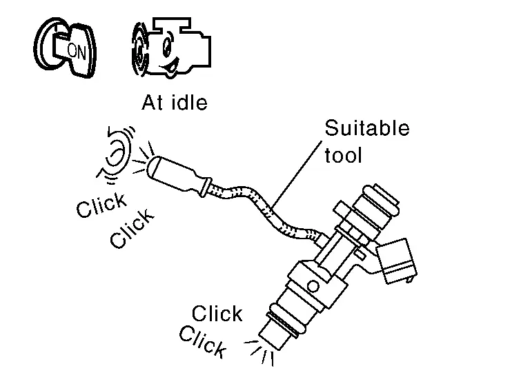
Clicking sound should be heard.
Is the inspection result normal?
YES>>
GO TO 6.
NO>>
Perform trouble diagnosis for FUEL INJECTOR, refer to Diagnosis Procedure.
CHECK FUNCTION OF IGNITION COIL-I
CAUTION:
Perform the following procedure in a place where with no combustible objects and good ventilation.
-
Turn ignition switch OFF.
-
Pull out 20A fuse (No.85) from IPDM E/R to release fuel pressure. Refer to IPDM E/R Terminal Arrangement .
 NOTE:
NOTE: Do not use CONSULT to release fuel pressure, or fuel pressure applies again during the following procedure.
-
Start engine.
-
After engine stalls, crank it two or three times to release all fuel pressure.
-
Turn ignition switch OFF.
-
Remove all ignition coil harness connectors to avoid the electrical discharge from the ignition coils.
-
Remove ignition coil and spark plug of the cylinder to be checked.
-
Crank engine for 5 seconds or more to remove combustion gas in the cylinder.
-
Connect spark plug and harness connector to ignition coil.
-
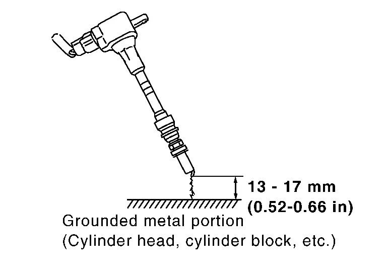
Fix ignition coil using a rope etc. with gap of 13 – 17 mm (0.52 – 0.66 in) between the edge of the spark plug and grounded metal portion as shown in the figure.
-
Crank engine for about 3 seconds, and check whether spark is generated between the spark plug and the grounded metal portion.
Spark should be generated. CAUTION:
-
Never place the spark plug and the ignition coil within 50 cm (19.7 in) each other. Be careful not to get an electrical shock while checking, because the electrical discharge voltage becomes 20 kV or more.
-
It might damage the ignition coil if the gap of more than 17 mm (0.66 in) is made.
 NOTE:
NOTE: When the gap is less than 13 mm (0.52 in), a spark might be generated even if the coil is malfunctioning.
-
Is the inspection result normal?
YES>>
GO TO 10.
NO>>
GO TO 7.
CHECK FUNCTION OF IGNITION COIL-II
-
Turn ignition switch OFF.
-
Disconnect spark plug and connect a non-malfunctioning spark plug.
-
Crank engine for about 3 seconds, and recheck whether spark is generated between the spark plug and the grounded metal portion.
Spark should be generated.
Is the inspection result normal?
YES>>
GO TO 8.
NO>>
Check ignition coil, power transistor and their circuits. Refer to Diagnosis Procedure.
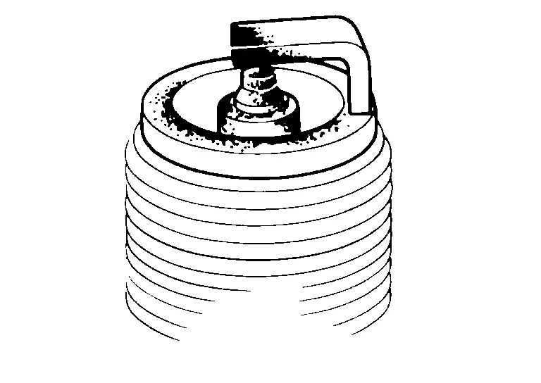
CHECK SPARK PLUG
Check the initial spark plug for fouling, etc.
Is the inspection result normal?
YES>>
Replace spark plug(s) with standard type one(s). For spark plug type, refer to Exploded View.
NO>>
Repair or clean spark plug. Then GO TO 9.
CHECK FUNCTION OF IGNITION COIL-III
-
Reconnect the initial spark plugs.
-
Crank engine for about 3 seconds, and recheck whether spark is generated between the spark plug and the grounded portion.
Spark should be generated.
Is the inspection result normal?
YES>>
INSPECTION END
NO>>
Replace spark plug(s) with standard type one(s). For spark plug type, refer to Exploded View.
CHECK COMPRESSION PRESSURE
Check compression pressure. Refer to Exploded View.
Is the inspection result normal?
YES>>
GO TO 11.
NO>>
Check pistons, piston rings, valves, valve seats and cylinder head gaskets.
CHECK FUEL PRESSURE
-
Install all removed parts.
-
Release fuel pressure to zero. Refer to Work Procedure.
-
Install fuel pressure gauge and check fuel pressure. Refer to Work Procedure.
Is the inspection result normal?
YES>>
GO TO 13.
NO>>
GO TO 12.
DETECT MALFUNCTIONING PART
Check fuel hoses and fuel tubes for clogging.
Is the inspection result normal?
YES>>
Replace “fuel filter and fuel pump assembly”.
NO>>
Repair or replace.
CHECK IDLE SPEED AND IGNITION TIMING
For procedure, refer to Work Procedure.
For specification, refer to Idle Speed and Ignition Timing.
Is the inspection result normal?
YES>>
GO TO 14.
NO>>
Follow the Work Procedure.
CHECK A/F SENSOR 1 INPUT SIGNAL CIRCUIT
-
Turn ignition switch OFF.
-
Disconnect corresponding A/F sensor 1 harness connector.
-
Disconnect ECM harness connector.
-
Check the continuity between A/F sensor 1 harness connector and ECM harness connector.
Bank A/F sensor 1 ECM Continuity Connector Terminal Connector Terminal 1 F72 3 F79 102 Existed 4 101 2 F73 3 106 4 105 -
Check the continuity between A/F sensor 1 harness connector and ground, or ECM harness connector and ground.
Bank A/F sensor 1 — Continuity Connector Terminal 1 F72 3 Ground Existed 4 2 F73 3 4 Bank ECM — Continuity Connector Terminal 1 F79 101 Ground Existed 102 2 105 106 -
Also check harness for short to power.
Is the inspection result normal?
YES>>
GO TO 15.
NO>>
Repair open circuit, short to ground or short to power in harness or connectors.
CHECK A/F SENSOR 1 HEATER
Refer to Component Inspection (A/F Sensor 1 Heater).
Is the inspection result normal?
YES>>
GO TO 16.
NO>>
Replace (malfunctioning) A/F sensor 1. Refer to Exploded View.
CHECK MASS AIR FLOW SENSOR
 With CONSULT
Check “MASS AIR FLOW SENSOR (Hz)” in “Data Monitor” mode of “ENGINE”.
For specification, refer to Component Inspection (Mass Air Flow Sensor).
 With GST
Check mass air flow sensor signal in Service $01 with GST.
For specification, refer to Mass Air Flow Sensor.
Is the measurement value within the specification?
YES>>
GO TO 17.
NO>>
Check connectors for rusted terminals or loose connections in the mass air flow sensor circuit or ground. Refer to Diagnosis Procedure.
CHECK SYMPTOM TABLE
Check items on the rough idle symptom in Symptom Table.
Is the inspection result normal?
YES>>
GO TO 18.
NO>>
Repair or replace.
ERASE THE 1ST TRIP DTC
Some tests may cause a 1st trip DTC to be set.
Erase the 1st trip DTC from the ECM memory after performing the tests. Refer to CONSULT Function (With CONSULT).
>>
INSPECTION END
P0315 Crankshaft Position Nissan Pathfinder 2022
DTC Description
DTC DETECTION LOGIC
| DTC |
CONSULT screen terms (Trouble diagnosis content) |
DTC detection condition | ||
| P0315 | 00 |
Crankshaft position (Crankshaft Position System Variation Not Learned) |
Diagnosis condition | Engine run and fuel shut off |
| Signal | — | |||
| Threshold | Learning value of signal plate variation is abnormal or not learned. | |||
| Diagnosis delay time | — | |||
POSSIBLE CAUSE
-
Signal plate
-
Crankshaft position sensor 1
-
Harness or connectors (Crankshaft position sensor 1 circuit is open or shorted.)
FAIL-SAFE
Not applicable
DTC Confirmation Procedure
CHECK DTC PRIORITY
If DTC P0315 is displayed with DTC P0335, first perform the trouble diagnosis for DTC P0335.
Is applicable DTC detected?
YES>>Perform diagnosis of applicable. Refer to DTC Description.
NO>>GO TO 2.
PERFORM DTC CONFIRMATION PROCEDURE
-
Start the engine and warm it up to normal operating temperature.
-
Drive Nissan Pathfinder vehicle at 80 km/h (50 MPH), with selecting suitable gear.
 NOTE:
NOTE:
Always keep safe driving to the first priority.
-
Release accelerator pedal completely to decelerate the Nissan Pathfinder vehicle.
 NOTE:
NOTE:
Always keep safe driving to the first priority.
-
Repeat the step 2 and 3 until the integrated deceleration time to be 30 seconds.
-
Check 1st trip DTC.
Is 1st trip DTC detected?
YES>>Proceed to DIAGNOSIS PROCEDURE.
NO-1>>To check malfunction symptom before repair: Refer to Diagnosis Procedure.
NO-2>>Confirmation after repair: INSPECTION END
Diagnosis Procedure
CHECK DTC PRIORITY
If DTC P0315 is displayed with DTC P0335, first perform the trouble diagnosis for DTC P0335.
Is applicable DTC detected?
YES>>Perform diagnosis of applicable. Refer to DTC Description.
NO>>GO TO 2.
CHECK GEAR TOOTH
Visually check for chipping signal plate gear tooth.
Is the inspection result normal?
YES>>INSPECTION END
NO>>Replace the signal plate. Refer to Exploded View.
P0326 Knock Sensor Nissan Pathfinder 2022
DTC Description
DTC DETECTION LOGIC
| DTC |
CONSULT screen terms (Trouble diagnosis content) | DTC detected condition | ||
|---|---|---|---|---|
| P0326 | 00 |
KNOCK SENSOR 1 B1 (Knock/Combustion Vibration Sensor 1 Circuit Range/Performance Bank 1 or Single Sensor) |
Diagnosis condition | During fuel cut after engine warm-up |
| Signal | Knock sensor | |||
| Threshold | When the ECM detects knocking during engine running more than the threshold value | |||
| Diagnosis delay time | 5 seconds | |||
POSSIBLE CAUSE
Harness or connectors
(The knock sensor circuit is open or shorted.)
-
Knock sensor
-
Knock sensor installation
FAIL SAFE
Not applicable
DTC Confirmation Procedure
DTC CONFIRMATION PROCEDURE
CHECK DTC PRIORITY
If DTC P0326 is displayed with DTC P0327 or P0328, first perform the confirmation procedure (trouble diagnosis) for DTC P0327 or P0328.
Is applicable DTC detected?
YES>>Perform diagnosis of applicable. Refer to DTC Index.
NO>>GO TO 2.
PRECONDITIONING
If DTC Confirmation Procedure has been previously conducted, always perform the following procedure before conducting the next test.
-
Turn ignition switch OFF and wait at least 10 seconds.
-
Turn ignition switch ON.
-
Turn ignition switch OFF and wait at least 10 seconds.
TESTING CONDITION:
Before performing the following procedure, confirm that battery voltage is 10 V or more at idle.
>>
GO TO 3.
PERFORM DTC CONFIRMATION PROCEDURE
-
Start engine and warm it up to normal operating temperature.
-
Revving engine from idle up to 3,000 rpm quickly.
-
Repeat the step 2 at 10 times.
-
Check DTC.
Is DTC detected?
YES>>Proceed to Diagnosis Procedure.
NO-1>>To check malfunction symptom before repair: Refer to Intermittent Incident.
NO-2>>Confirmation after repair: INSPECTION END
Diagnosis Procedure
CHECK DTC PRIORITY
If DTC P0326 is displayed with DTC P0327 or P0328, first perform the confirmation procedure (trouble diagnosis) for DTC P0327 or P0328.
Is applicable DTC detected?
YES>>Perform diagnosis of applicable. Refer to Diagnosis Procedure.
NO>>GO TO 2.
CHECK INSTALLATION CONDITION OF KNOCK SENSOR
Visually check that the knock sensor is installed normally.
Is the inspection result normal?
YES>>GO TO 3.
NO>>Repair or replace error-detected parts.
CHECK INTERMITTENT INCIDENT
Check intermittent incident. Refer to Intermittent Incident.
Is the inspection result normal?
YES>>GO TO 4.
NO>>Repair or replace error-detected parts.
CHECK KNOCK SENSOR CIRCUIT
Check knock sensor circuit. Refer to Diagnosis Procedure.
Is the inspection result normal?
YES>>GO TO 5.
NO>>Repair or replace error-detected parts.
PERFORM DTC CONFIRMATION PROCEDURE
-
Turn ignition switch ON.
-
Erase DTC.
-
Perform DTC confirmation procedure. Refer to DTC Confirmation Procedure.
Is the 1st trip DTC P0326 displayed again?
YES>>Replace ECM. Refer to Removal and Installation .
NO>>INSPECTION END
P0327 Ks Nissan Pathfinder 2026
DTC Description
DTC DETECTION LOGIC
| DTC |
CONSULT screen terms (Trouble diagnosis content) |
DTC detection condition | ||
| P0327 | 00 |
KNOCK SEN/CIRC-B1 (Knock sensor 1 circuit low bank 1) |
Diagnosis condition | Engine running at idle |
| Signal (terminal) | Knock sensor (bank 1) signal | |||
| Threshold | An excessively low voltage from the sensor is sent to ECM | |||
| Diagnosis delay time | — | |||
POSSIBLE CAUSE
-
Harness or connectors [The knock sensor (bank 1) circuit is open or shorted.]
-
Knock sensor (bank 1)
FAIL-SAFE
Not applicable
DTC Confirmation Procedure
PRECONDITIONING
If DTC Confirmation Procedure has been previously conducted, always perform the following procedure before conducting the next test.
-
Turn ignition switch OFF and wait at least 10 seconds.
-
Turn ignition switch ON.
-
Turn ignition switch OFF and wait at least 10 seconds.
TESTING CONDITION:
Before performing the following procedure, confirm that battery voltage is more than 10 V at idle.
>>
GO TO 2.
PERFORM DTC CONFIRMATION PROCEDURE
-
Start engine and run it for at least 5 seconds at idle speed.
-
Check 1st trip DTC.
Is DTC P0327 detected?
YES>>Proceed to Diagnosis Procedure.
NO-1>>To check malfunction symptom before repair: Refer to Intermittent Incident.
NO-2>>Confirmation after repair: INSPECTION END
Diagnosis Procedure
CHECK KNOCK SENSOR GROUND CIRCUIT
-
Turn ignition switch OFF.
-
Disconnect knock sensor harness connector and ECM harness connector.
-
Check the continuity between knock sensor harness connector and ECM harness connector.
Knock sensor ECM Continuity Bank Connector Terminal Connector Terminal 1 F211 2 F78 8 Existed -
Also check harness for short to power.
Is the inspection result normal?
YES>>GO TO 2.
NO>>Repair or replace error-detected parts.
CHECK ECM GROUND CIRCUIT
-
Check the continuity between ECM harness connector and ground.
ECM — Continuity Connector Terminal F78 3 Ground Existed F79 87 E32 199 201 204 -
Also check harness for short to power.
Is the inspection result normal?
YES>>GO TO 3.
NO>>Repair or replace error-detected parts.
CHECK KNOCK SENSOR INPUT SIGNAL CIRCUIT
-
Check the continuity between knock sensor harness connector and ECM harness connector.
Knock sensor ECM Continuity Bank Connector Terminal Connector Terminal 1 F211 1 F78 7 Existed -
Also check harness for short to power and short to ground.
Is the inspection result normal?
YES>>GO TO 4.
NO>>Repair or replace error-detected parts.
CHECK KNOCK SENSOR
Refer to Component Inspection.
Is the inspection result normal?
YES>>INSPECTION END
NO>>Replace malfunctioning knock sensor. Refer to Exploded View.
Component Inspection
CHECK KNOCK SENSOR
-
Turn ignition switch OFF.
-
Disconnect knock sensor harness connector.
-
Check resistance between knock sensor terminals as per the following.
 NOTE:
NOTE:
It is necessary to use an ohmmeter which can measure more than 10 MΩ.
| Knock sensor | Condition | Resistance | ||
|---|---|---|---|---|
| Terminal | ||||
| 1 | 2 | Temperature [°C (°F)] | 20 (68) | 532 – 588 kΩ |
CAUTION:
Do not use any knock sensors that have been dropped or physically damaged. Use only new ones.
Is the inspection result normal?
YES>>INSPECTION END
NO>>Replace malfunctioning knock sensor. Refer to Exploded View.
P0335 Crankshaft Position Sensor Nissan Pathfinder Fifth generation
DTC Description
DTC DETECTION LOGIC
| DTC |
CONSULT screen terms (Trouble diagnosis content) |
DTC detection condition | ||
| P0335 | 00 |
CKP SEN/CIRCUIT (Crankshaft position sensor “A” circuit) |
Diagnosis condition |
|
| Signal (terminal) | Crankshaft position sensor 1 signal | |||
| Threshold |
|
|||
| Diagnosis delay time | 1 second or more | |||
POSSIBLE CAUSE
-
Harness or connectors
(Crankshaft position sensor 1 circuit is open or shorted.)
-
Crankshaft position sensor 1
-
Signal plate (drive plate)
FAIL-SAFE
| Fail safe mode | Nissan Pathfinder Vehicle behavior | |
|---|---|---|
| Device fix mode |
|
|
| Combustion control mode | Stratified charge combustion control at starting | No stratified charge combustion at starting (cold start). |
| Idle speed control | Stops feedback control of idle speed and controls with specified speed. | |
| Recovery speed control at decelerating | Stops recovery speed control by the fuel cut at decelerating and controls with specified speed. | |
| Idle neutral control | Stops idle neutral control. | |
DTC Confirmation Procedure
PRECONDITIONING
If DTC Confirmation Procedure has been previously conducted, always perform the following procedure before conducting the next test.
-
Turn ignition switch OFF and wait at least 10 seconds.
-
Turn ignition switch ON.
-
Turn ignition switch OFF and wait at least 10 seconds.
 NOTE:
NOTE:
Before performing the following procedure, check that battery voltage as the following.
-
Ignition switch ON: More than 11 V
-
Engine cranking: More than 7 V
>>
GO TO 2.
PERFORM DTC CONFIRMATION PROCEDURE
-
Turn ignition switch ON.
-
Shift the selector lever in N range.
-
Start the engine and let it idle at least 5 seconds.
-
Check DTC.
Is DTC P0335 detected?
YES>>
Proceed to Diagnosis Procedure.
NO-1>>
To check malfunction symptom before repair: Refer to Intermittent Incident.
NO-2>>
Confirmation after repair: INSPECTION END
Diagnosis Procedure
CHECK HARNESS CONNECTOR
-
Turn ignition switch OFF.
-
Disconnect crankshaft position (CKP) sensor 1 harness connectors.
-
Reconnect crankshaft position (CKP) sensor 1 harness connectors.
-
Perform DTC confirmation procedure.
Is DTC detected?
YES>>
GO TO 2.
NO>>
INSPECTION END
CHECK GROUND CONNECTION
Check ground connection.
Is the inspection result normal?
YES>>
GO TO 3.
NO>>
Repair or replace ground connection.
CHECK CRANKSHAFT POSITION (CKP) SENSOR 1 POWER SUPPLY
-
Turn ignition switch OFF.
-
Disconnect crankshaft position sensor 1 harness connector.
-
Turn ignition switch ON.
-
Check the voltage between CKP sensor 1 harness connector and ground.
+ − Voltage
(Approx.)CKP sensor 1 Connector Terminal F11 1 Ground 5 V
Is the inspection result normal?
YES>>
GO TO 5.
NO>>
GO TO 4.
CHECK CKP SENSOR 1 POWER SUPPLY CIRCUIT
-
Turn ignition switch OFF
-
Disconnect ECM harness connector.
-
Check the continuity between CKP sensor 1 harness connector and ECM harness connector.
CKP sensor 1 ECM Continuity Connector Terminal Connector Terminal F11 1 F78 39 Existed -
Also check harness for short to power and short to ground.
Is the inspection result normal?
YES>>
Perform the trouble diagnosis for ECM power supply circuit.
NO>>
Repair or replace error-detected parts.
CHECK CKP SENSOR 1 GROUND CIRCUIT
-
Turn ignition switch OFF.
-
Disconnect ECM harness connector.
-
Check the continuity between CKP sensor 1 harness connector and ECM harness connector.
CKP sensor 1 ECM Continuity Connector Terminal Connector Terminal F11 2 F78 22 Existed -
Also check harness for short to power.
Is the inspection result normal?
YES>>
GO TO 6.
NO>>
Repair or replace error-detected parts.
CHECK CKP SENSOR 1 INPUT SIGNAL CIRCUIT
-
Check the continuity between CKP sensor 1 harness connector and ECM harness connector.
CKP sensor 1 ECM Continuity Connector Terminal Connector Terminal F11 3 F78 31 Existed -
Also check harness for short to power and short to ground.
Is the inspection result normal?
YES>>
GO TO 7.
NO>>
Repair or replace error-detected parts.
CHECK CKP SENSOR 1
Check CKP sensor 1. Refer to Component Inspection.
Is the inspection result normal?
YES>>
GO TO 8.
NO>>
Replace CKP sensor 1. Refer to Exploded View.
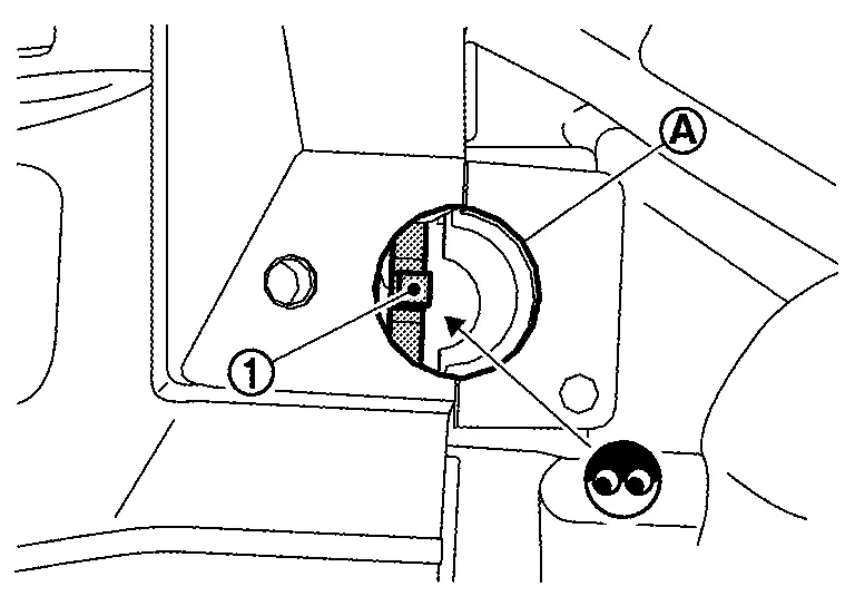
CHECK GEAR TOOTH
-
Remove CKP sensor 1. Refer to Exploded View.
-
Look into the mounting hole
 of the CKP sensor 1 to check that there is no missing gear tooth in the signal plate
  .
.
Is the inspection result normal?
YES>>
INSPECTION END
NO>>
Replace the signal plate (drive plate). Refer to Exploded View.
Component Inspection
CHECK CRANKSHAFT POSITION (CKP) SENSOR 1-I
-
Turn ignition switch OFF.
-
Loosen the fixing bolt of the sensor.
-
Disconnect CKP sensor 1 harness connector.
-
Remove the sensor.
-
Visually check the sensor for chipping.
Is the inspection result normal?
YES>>
GO TO 2.
NO>>
Replace CKP sensor 1. Refer to Exploded View.
CHECK CKP SENSOR-II
Check the resistance between CKP sensor terminals as per the following.
| CKP sensor 1 | Condition | Resistance | ||
|---|---|---|---|---|
| Terminal (Polarity) | ||||
| 1 | 2 | Temperature [°C (°F)] | 25 (77) | Except 0 or ∞Ω |
| 3 | ||||
| 2 | 3 | |||
Is the inspection result normal?
YES>>
INSPECTION END
NO>>
Replace CKP sensor 1. Refer to Exploded View.
P0340 Cmp Sensor Nissan Pathfinder
DTC Description
DTC DETECTION LOGIC
| DTC |
CONSULT screen terms (Trouble diagnosis content) |
DTC detection condition | ||
|---|---|---|---|---|
| P0340 | 00 |
CMP SEN/CIRC-B1 (Camshaft position sensor “A” circuit bank 1) |
Diagnosis condition | Engine: Cranking or running (idle speed or more than 800 rpm) |
| Signal (terminal) | Intake camshaft position sensor (PHASE) (bank 1) signal | |||
| Threshold |
|
|||
| Diagnosis delay time | — | |||
POSSIBLE CAUSE
-
Harness or connectors [Intake camshaft position sensor (bank 1) circuit is open or shorted.]
-
Intake camshaft position sensor (bank 1)
-
Camshaft (INT)
-
Starter motor
-
Starting system circuit
-
Dead (Weak) battery
FAIL-SAFE
| Fail safe mode | Nissan Pathfinder Vehicle behavior | |
|---|---|---|
| Device fix mode |
|
|
| Combustion control mode | Stratified charge combustion control at starting | No stratified charge combustion at starting (cold start). |
| Idle speed control | Stops feedback control of idle speed and controls with specified speed. | |
| Recovery speed control at decelerating | Stops recovery speed control by the fuel cut at decelerating and controls with specified speed. | |
| Idle neutral control | Stops idle neutral control. | |
DTC Confirmation Procedure
CHECK DTC PRIORITY
If DTC P0340 is displayed with DTC P0643, first perform the confirmation procedure (trouble diagnosis) for DTC P0643.
Is DTC P0643 detected?
YES>>
Perform diagnosis of applicable. Refer to DTC Description.
NO>>
GO TO 2.
PRECONDITIONING
If DTC Confirmation Procedure has been previously conducted, always perform the following procedure before conducting the next test.
-
Turn ignition switch OFF and wait at least 10 seconds.
-
Turn ignition switch ON.
-
Turn ignition switch OFF and wait at least 10 seconds.
TESTING CONDITION:
Before performing the following procedure, confirm that battery voltage is more than 10.5 V with ignition switch ON.
>>
GO TO 3.
PERFORM DTC CONFIRMATION PROCEDURE-I
-
Start engine and let it idle for at least 5 seconds.
If engine does not start, crank engine for at least 2 seconds.
-
Check 1st trip DTC.
Is DTC P0340 detected?
YES>>
Proceed to Diagnosis Procedure.
NO>>
GO TO 4.
PERFORM DTC CONFIRMATION PROCEDURE-II
-
Maintaining engine speed at more than 800 rpm for at least 5 seconds.
-
Check 1st trip DTC.
Is DTC P0340 detected?
YES>>
Proceed to Diagnosis Procedure.
NO-1>>
To check malfunction symptom before repair: Refer to Intermittent Incident.
NO-2>>
Confirmation after repair: INSPECTION END
Diagnosis Procedure
CHECK DTC PRIORITY
If DTC P0340 is displayed with DTC P0643, first perform the confirmation procedure (trouble diagnosis) for DTC P0643.
Is DTC P0643 detected?
YES>>
Perform diagnosis of applicable. Refer to DTC Description.
NO>>
GO TO 2.
CHECK STARTING SYSTEM
Turn ignition switch to START position.
Does the engine turn over? Does the starter motor operate?
YES>>
GO TO 3.
NO>>
Check starting system. (Refer to Work Flow (With 165–DSS-5000P) or Work Flow (Without 165–DSS-5000P). For details, Refer to Special Service Tool.)
CHECK GROUND CONNECTION
-
Turn ignition switch OFF.
-
Check ground connection E9. Refer to Ground Inspection in Circuit Inspection.
Is the inspection result normal?
YES>>
GO TO 4.
NO>>
Repair or replace ground connection.
CHECK INTAKE CAMSHAFT POSITION SENSOR POWER SUPPLY
-
Disconnect intake camshaft position sensor harness connector.
-
Turn ignition switch ON.
-
Check the voltage between intake camshaft position sensor harness connector and ground.
+ − Voltage
(Approx.)Intake camshaft position sensor Bank Connector Terminal 1 F113 1 Ground 5 V
Is the inspection result normal?
YES>>
GO TO 7.
NO>>
GO TO 5.
CHECK INTAKE CAMSHAFT POSITION SENSOR POWER SUPPLY CIRCUIT
-
Turn ignition switch OFF.
-
Disconnect ECM harness connector.
-
Check the continuity between intake camshaft position sensor harness connector and ECM harness connector.
Intake camshaft position sensor ECM Continuity Bank Connector Terminal Connector Terminal 1 F113 1 F78 40 Existed -
Also check harness for short to power and short to ground.
Is the inspection result normal?
YES-1>>
P0340: Perform the trouble diagnosis for ECM power supply circuit. Refer to Diagnosis Procedure.
YES-2>>
P0345: GO TO 6.
NO>>
Repair or replace error-detected parts.
CHECK SENSOR POWER SUPPLY 2 CIRCUIT
Refer to Diagnosis Procedure.
Is the inspection result normal?
YES>>
Perform the trouble diagnosis for ECM power supply circuit. Refer to Diagnosis Procedure.
NO>>
Repair or replace error-detected parts.
CHECK INTAKE CAMSHAFT POSITION SENSOR GROUND CIRCUIT
-
Turn ignition switch OFF.
-
Disconnect ECM harness connector.
-
Check the continuity between intake camshaft position sensor harness connector and ECM harness connector.
Intake camshaft position sensor ECM Continuity Bank Connector Terminal Connector Terminal 1 F113 2 F78 27 Existed -
Also check harness for short to power.
Is the inspection result normal?
YES>>
GO TO 8.
NO>>
Repair or replace error-detected parts.
CHECK INTAKE CAMSHAFT POSITION SENSOR INPUT SIGNAL CIRCUIT
-
Check the continuity between intake camshaft position sensor harness connector and ECM harness connector.
Intake camshaft position sensor ECM Continuity Bank Connector Terminal Connector Terminal 1 F113 3 F78 36 Existed -
Also check harness for short to power and short to ground.
Is the inspection result normal?
YES>>
GO TO 9.
NO>>
Repair or replace error-detected parts.
CHECK INTAKE CAMSHAFT POSITION SENSOR
Refer to Component Inspection.
Is the inspection result normal?
YES>>
GO TO 10.
NO>>
Replace malfunctioning intake camshaft position sensor. Refer to Exploded View.
CHECK CAMSHAFT (INTAKE)
Check the following.
-
Accumulation of debris to the signal plate of camshaft rear end
-
Chipping signal plate of camshaft rear end
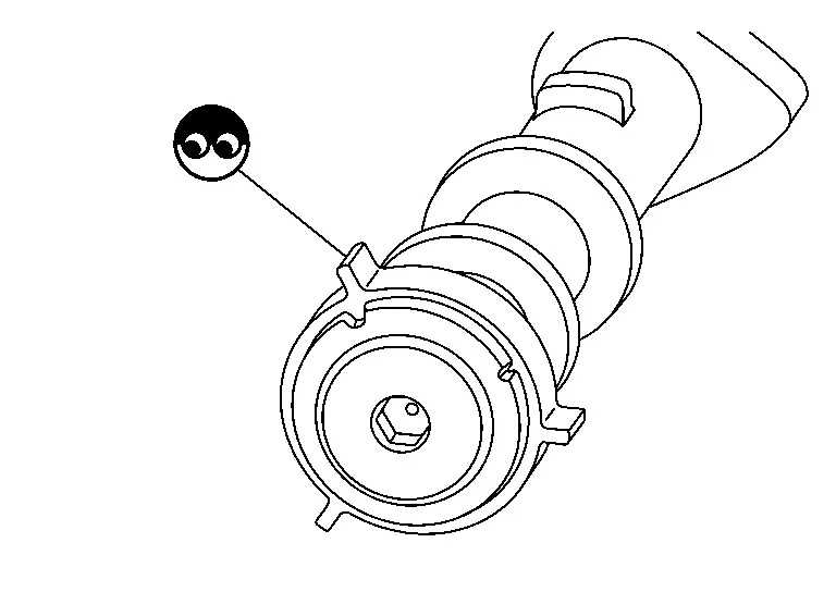
Is the inspection result normal?
YES>>
INSPECTION END
NO>>
Remove debris and clean the signal plate of camshaft rear end or replace camshaft. Refer to Removal and Installation.
Component Inspection
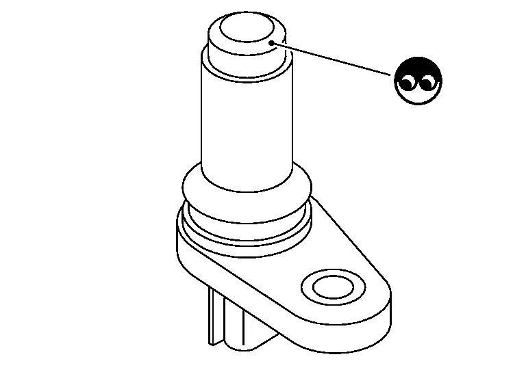
CHECK INTAKE CAMSHAFT POSITION (CMP) SENSOR-I
-
Turn ignition switch OFF.
-
Disconnect intake CMP sensor harness connector.
-
Remove the sensor. Refer to Exploded View.
-
Visually check the sensor for chipping.

Is the inspection result normal?
YES>>
GO TO 2.
NO>>
Replace the malfunctioning intake CMP sensor. Refer to Exploded View.
CHECK INTAKE CMP SENSOR-II
Check resistance intake CMP sensor terminals as follows.
| Intake CMP sensor | Condition | Resistance | ||
|---|---|---|---|---|
| Terminal (Polarity) | ||||
| 1 | 2 | Temperature [°C (°F)] | 25 (77) | Except 0 or ∞Ω |
| 3 | ||||
| 2 | 3 | |||
Is the inspection result normal?
YES>>
INSPECTION END
NO>>
Replace the malfunctioning intake CMP sensor. Refer to Exploded View.
P0365 Exhaust Camshaft Position Sensor Nissan Pathfinder R53
DTC Description
DTC DETECTION LOGIC
| DTC |
CONSULT screen terms (Trouble diagnosis content) |
DTC detection condition | ||
| P0365 | 00 |
CAMSHAFT POSITION SENSOR B B1 (Camshaft position sensor “B” circuit bank 1) |
Diagnosis condition | Engine running at idle |
| Signal (terminal) | Exhaust camshaft position sensor (bank 1) signal | |||
| Threshold |
|
|||
| Diagnosis delay time | 1 second or more | |||
POSSIBLE CAUSE
-
Harness or connectors [Exhaust camshaft position sensor (bank 1) circuit is open or shorted.]
-
Exhaust camshaft position sensor (bank 1)
-
Exhaust camshaft (bank 1) (sensor rotor)
FAIL-SAFE
| Fail safe mode | Nissan Pathfinder Vehicle behavior | |
|---|---|---|
| Device fix mode |
|
|
DTC Confirmation Procedure
PRECONDITIONING
If DTC Confirmation Procedure has been previously conducted, always perform the following procedure before conducting the next test.
-
Turn ignition switch OFF and wait at least 10 seconds.
-
Turn ignition switch ON.
-
Turn ignition switch OFF and wait at least 10 seconds.
 NOTE:
NOTE:
Before performing the following procedure, check that battery voltage as the following.
-
Ignition switch ON: More than 11 V
-
Engine cranking: More than 7 V
>>
GO TO 2.
PERFORM DTC CONFIRMATION PROCEDURE
-
Turn ignition switch ON.
-
Shift the selector lever in N range.
-
Start the engine and let it idle at least 5 seconds.
-
Check DTC.
Is DTC P0365 detected?
YES>>Proceed to Diagnosis Procedure.
NO-1>>To check malfunction symptom before repair: Refer to Intermittent Incident.
NO-2>>Confirmation after repair: INSPECTION END
Diagnosis Procedure
CHECK EXHAUST CAMSHAFT POSITION (CMP) SENSOR (BANK 1) POWER SUPPLY
-
Turn ignition switch OFF.
-
Disconnect exhaust CMP sensor (bank 1) harness connector.
-
Turn ignition switch ON.
-
Check the voltage between exhaust CMP sensor (bank 1) harness connector and ground.
+ − Voltage
(Approx.)Exhaust CMP sensor (bank 1) Connector Terminal F43 1 Ground 5 V
Is the inspection result normal?
YES>>GO TO 3.
NO>>GO TO 2.
CHECK EXHAUST CMP SENSOR (BANK 1) POWER SUPPLY CIRCUIT
-
Turn ignition switch OFF
-
Disconnect ECM harness connector.
-
Check the continuity between exhaust CMP sensor (bank 1) harness connector and ECM harness connector.
Exhaust CMP sensor (bank 1) ECM Continuity Connector Terminal Connector Terminal F43 1 F78 38 Existed -
Also check harness for short to power and short to ground.
Is the inspection result normal?
YES>>Perform the trouble diagnosis for ECM power supply circuit.
NO>>Repair or replace error-detected parts.
CHECK EXHAUST CMP SENSOR (BANK 1) GROUND CIRCUIT
-
Turn ignition switch OFF.
-
Disconnect ECM harness connector.
-
Check the continuity between exhaust CMP sensor (bank 1) harness connector and ECM harness connector.
Exhaust CMP sensor (bank 1) ECM Continuity Connector Terminal Connector Terminal F43 2 F78 28 Existed -
Also check harness for short to power.
Is the inspection result normal?
YES>>GO TO 4.
NO>>Repair or replace error-detected parts.
CHECK EXHAUST CMP SENSOR (BANK 1) INPUT SIGNAL CIRCUIT
-
Check the continuity between exhaust CMP sensor (bank 1) harness connector and ECM harness connector.
Exhaust CMP sensor (bank 1) ECM Continuity Connector Terminal Connector Terminal F43 3 F78 34 Existed -
Also check harness for short to power and short to ground.
Is the inspection result normal?
YES>>GO TO 5.
NO>>Repair or replace error-detected parts.
CHECK EXHAUST CMP SENSOR (BANK 1)
Check exhaust CMP sensor (bank 1). Refer to Component Inspection.
Is the inspection result normal?
YES>>GO TO 6.
NO>>Replace exhaust CMP sensor (bank 1). Refer to Exploded View.
CHECK EXHAUST CAMSHAFT (BANK 1)
Check the following items:
-
Accumulation of debris to the signal plate exhaust camshaft (bank 1) rear end
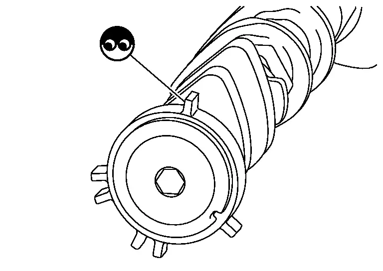
-
Chipping signal plate of camshaft rear end
Is the inspection result normal?
YES>>INSPECTION END
NO>>Remove debris and clean the signal plate of the camshaft rear end or replace the camshaft. Refer to Removal and Installation.
Component Inspection
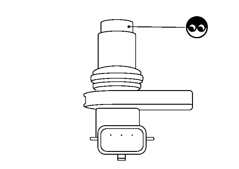
CHECK EXHAUST CAMSHAFT POSITION (CMP) SENSOR-I
-
Turn ignition switch OFF.
-
Disconnect exhaust CMP sensor harness connector.
-
Remove the sensor. Refer to Exploded View.
-
Visually check the sensor for chipping.
Is the inspection result normal?
YES>>GO TO 2.
NO>>Replace the malfunctioning exhaust CMP sensor. Refer to Exploded View.
CHECK EXHAUST CMP SENSOR-II
Check resistance exhaust CMP sensor terminals as follows.
| Exhaust CMP sensor | Condition | Resistance | ||
|---|---|---|---|---|
| Terminal (Polarity) | ||||
| 1 | 2 | Temperature [°C (°F)] | 25 (77) | Except 0 or ∞Ω |
| 3 | ||||
| 2 | 3 | |||
Is the inspection result normal?
YES>>INSPECTION END
NO>>Replace the malfunctioning exhaust CMP sensor. Refer to Exploded View.
P0385 Ckp Sensor 2 Nissan Pathfinder Fifth generation
DTC Description
DTC DETECTION LOGIC
| DTC |
CONSULT screen terms (Trouble diagnosis content) |
DTC detection condition | ||
| P0385 | 00 |
CKP SENSOR B (Crankshaft Position Sensor "B" Circuit) |
Diagnosis condition | Engine running |
| Signal (terminal) | Crankshaft position sensor 2 signal | |||
| Threshold | The proper pulse signal from the crankshaft position sensor 2 is not sent to ECM while the engine is running. | |||
| Diagnosis delay time | — | |||
POSSIBLE CAUSE
-
Harness or connectors
(Crankshaft position sensor 2 circuit is open or shorted.)
-
Crankshaft position sensor 2
FAIL-SAFE
Engine Control System
Not applicable
Stop/start System
When a DTC is detected, the stop/start indicator blinks slowly and the stop/start system operation is prohibited.
When ECM detects error while operating the stop/start system, ECM restarts the engine.
DTC Confirmation Procedure
PRECONDITIONING
If DTC Confirmation Procedure has been previously conducted, always perform the following procedure before conducting the next test.
-
Turn ignition switch OFF and wait at least 10 seconds.
-
Turn ignition switch ON.
-
Turn ignition switch OFF and wait at least 10 seconds.
TESTING CONDITION:
Before performing the following procedure, confirm that battery voltage is more than 10.5 V at idling.
>>
GO TO 2.
PERFORM DTC CONFIRMATION PROCEDURE
-
Start engine and let it idle for at least 5 seconds.
If engine does not start, crank engine for at least 2 seconds.
-
Check 1st trip DTC.
Is DTC detected?
YES>>Refer to DTC Diagnosis Procedure.
NO-1>>To check malfunction symptom before repair: Refer to Intermittent Incident.
NO-2>>Confirmation after repair: INSPECTION END
DTC Diagnosis Procedure
CHECK CRANKSHAFT POSITION SENSOR 2 POWER SUPPLY-1
-
Turn ignition switch OFF
-
Disconnect crankshaft position sensor 2 harness connector.
-
Turn ignition switch ON.
-
Check the voltage between crankshaft position sensor 2 harness connector terminal.
| Crankshaft position sensor 2 | Condition |
Voltage (Approx.) | ||
|---|---|---|---|---|
| Connector | + | − | ||
| Terminal | ||||
| F91 | 1 | 2 | Ignition switch ON | 5 V |
| Ignition switch OFF | 0 V | |||
Is the inspection result normal?
YES>>GO TO 2.
NO>>GO TO 4.
CHECK CRANKSHAFT POSITION SENSOR 2 SIGNAL CIRCUIT
-
Turn ignition switch OFF
-
Disconnect ECM harness connector.
-
Check the continuity between crankshaft position sensor 2 harness connector and ECM harness connector.
+ − Continuity Crankshaft position sensor 2 ECM Connector Terminal Connector Terminal F91 3 F78 74 Existed -
Also check harness for short to ground.
Is the inspection result normal?
YES>>GO TO 3.
NO>>Repair or replace error-detected parts.
CHECK CRANKSHAFT POSITION SENSOR 2
Check crankshaft position sensor 2. Refer to Component Inspection (Crankshaft Position Sensor 2).
Is the inspection result normal?
YES>>Check intermittent incident. Refer to Intermittent Incident.
NO>>Repair or replace error-detected parts.
CHECK CRANKSHAFT POSITION SENSOR 2 POWER SUPPLY-2
Check the continuity between crankshaft position sensor 2 harness connector and ground.
| + | − | Condition |
Voltage (Approx.) | |
|---|---|---|---|---|
| Crankshaft position sensor 2 | ||||
| Connector | Terminal | |||
| F91 | 1 | Ground | Ignition switch ON | 5 V |
| Ignition switch OFF | 0 V | |||
Is the inspection result normal?
YES>>GO TO 5 .
NO>>GO TO 6.
CHECK CRANKSHAFT POSITION SENSOR 2 GROUND CIRCUIT
-
Turn ignition switch OFF
-
Disconnect ECM harness connector.
-
Check the continuity between crankshaft position sensor 2 harness connector and ECM harness connector.
| + | − | Continuity | ||
|---|---|---|---|---|
| Crankshaft position sensor 2 | ECM | |||
| Connector | Terminal | Connector | Terminal | |
| F91 | 2 | F78 | 77 | Existed |
Is the inspection result normal?
YES>>Check intermittent incident. Refer to Intermittent Incident.
NO>>Repair or replace error-detected parts.
CHECK CRANKSHAFT POSITION SENSOR 2 POWER SUPPLY CIRCUIT
-
Turn ignition switch OFF
-
Disconnect ECM harness connector.
-
Check the continuity between crankshaft position sensor 2 harness connector and ECM harness connector.
| + | − | Continuity | ||
|---|---|---|---|---|
| Crankshaft position sensor 2 | ECM | |||
| Connector | Terminal | Connector | Terminal | |
| F91 | 1 | F78 | 63 | Existed |
Is the inspection result normal?
YES>>Check intermittent incident. Refer to Intermittent Incident.
NO>>Repair or replace error-detected parts.
P0420 Three Way Catalyst Function Nissan Pathfinder SUV
DTC Description
The ECM monitors the switching frequency ratio of air fuel ratio (A/F) sensor 1 and heated oxygen sensor 2.
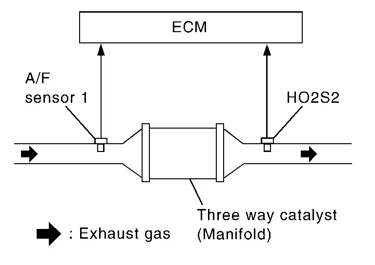
A three way catalyst 1 with high oxygen storage capacity will indicate a low switching frequency of heated oxygen sensor 2. As oxygen storage capacity decreases, the heated oxygen sensor 2 switching frequency will increase.
When the frequency ratio of A/F sensor 1 and heated oxygen sensor 2 approaches a specified limit value, the three way catalyst 1 malfunction is diagnosed.
DTC DETECTION LOGIC
| DTC |
CONSULT screen terms (Trouble diagnosis content) |
DTC detection condition | ||
| P0420 | 00 |
TW CATALYST SYS-B1 (Catalyst system efficiency below threshold bank 1) |
Diagnosis condition | — |
| Signal (terminal) | — | |||
| Threshold |
|
|||
| Diagnosis delay time | — | |||
POSSIBLE CAUSE
-
Three way catalyst (manifold)
-
Exhaust tube
-
Intake air leaks
-
Fuel injector
-
Fuel injector leaks
-
Spark plug
-
Improper ignition timing
FAIL-SAFE
Not applicable
DTC Confirmation Procedure
INSPECTION START
Do you have CONSULT?
YES>>
GO TO 2.
NO>>
GO TO 7.
PRECONDITIONING
If DTC Confirmation Procedure has been previously conducted, always perform the following procedure before conducting the next test.
-
Turn ignition switch OFF and wait at least 10 seconds.
-
Turn ignition switch ON.
-
Turn ignition switch OFF and wait at least 10 seconds.
TESTING CONDITION:
Do not hold engine speed for more than the specified minutes below.
>>
GO TO 3.
PERFORM DTC CONFIRMATION PROCEDURE-I
 With CONSULT
-
Turn ignition switch ON.
-
On CONSULT screen, select “ENGINE”>>“Data Monitor”.
-
Start engine and warm it up to the normal operating temperature.
-
Turn ignition switch OFF and wait at least 10 seconds.
-
Turn ignition switch ON.
-
Turn ignition switch OFF and wait at least 10 seconds.
-
Start engine and keep the engine speed between 3,500 and 4,000 rpm for at least 1 minute under no load.
-
Let engine idle for 1 minute.
-
Make sure that “COOLAN TEMP/S” indicates more than 70°C (158°F).
If not, warm up engine and go to next step when “COOLAN TEMP/S” indication reaches 70°C (158°F).
-
Open engine hood.
-
On CONSULT screen, select “DTC & SRT CONFIRMATION”>>“SRT WORK SUPPORT”.
-
Rev engine up to about 2,000 rpm and hold it for 3 consecutive minutes then release the accelerator pedal completely.
-
Check the indication of “CATALYST”.
Which is displayed on CONSULT screen?
CMPLT>>
GO TO 6.
INCMP>>
GO TO 4.
PERFORM DTC CONFIRMATION PROCEDURE-II
-
Wait 5 seconds at idle.
-
Rev engine up to about 2,000 rpm and maintain it until “INCMP” of “CATALYST” changes to “CMPLT” (It will take approximately 5 minutes).
Does the indication change to “CMPLT”?
YES>>
GO TO 6.
NO>>
GO TO 5.
PERFORM DTC CONFIRMATION PROCEDURE AGAIN
-
Stop engine and cool it down to less than 70°C (158°F).
-
Perform DTC CONFIRMATION PROCEDURE again.
>>
GO TO 3.
PERFORM DTC CONFIRMATION PROCEDURE-III
Check 1st trip DTC.
Is DTC P0420 detected?
YES>>
Proceed to Diagnosis Procedure.
NO-1>>
To check malfunction symptom before repair: Refer to Intermittent Incident.
NO-2>>
Confirmation after repair: INSPECTION END
PERFORM COMPONENT FUNCTION CHECK
 NOTE:
NOTE:
Use component function check to check the overall function of the three way catalyst (manifold). During this check, a 1st trip DTC might not be confirmed.
 Without CONSULT
-
Start engine and warm it up to the normal operating temperature.
-
Turn ignition switch OFF and wait at least 10 seconds.
-
Start engine and keep the engine speed between 3,500 and 4,000 rpm for at least 1 minute under no load.
-
Let engine idle for 1 minute.
-
Open engine hood.
-
Check the voltage between ECM harness connector terminals under the following condition.
ECM Condition Voltage Connector + – Terminal F78 49
[HO2S2 (bank 1)]81 Keeping engine speed at 2,500 rpm constant under no load The voltage fluctuation cycle takes more than 5 seconds.
-
1 cycle: 0.6 - 1.0 → 0 - 0.3 → 0.6 - 1.0
-
Is the inspection result normal?
YES-1>>
To check malfunction symptom before repair: Refer to Intermittent Incident.
YES-2>>
Confirmation after repair: INSPECTION END
NO>>
Proceed to Diagnosis Procedure.
Diagnosis Procedure
CHECK EXHAUST SYSTEM
Visually check exhaust tubes and muffler for dents.
Is the inspection result normal?
YES>>
GO TO 2.
NO>>
Repair or replace.
CHECK EXHAUST GAS LEAK
-
Start engine and run it at idle.
-
Listen for an exhaust gas leak before the three way catalyst 1.

Is exhaust gas leak detected?
YES>>
Repair or replace.
NO>>
GO TO 3.
CHECK INTAKE AIR LEAK
Listen for an intake air leak after the mass air flow sensor.
Is intake air leak detected?
YES>>
Repair or replace.
NO>>
GO TO 4.
CHECK IDLE SPEED AND IGNITION TIMING
For procedure, refer to Work Procedure.
For specification, refer to Idle Speed and Ignition Timing.
Is the inspection result normal?
YES>>
GO TO 5.
NO>>
Follow the Work Procedure.
CHECK FUEL INJECTORS
Check the fuel injector. Refer to Component Function Check.
Is the inspection result normal?
YES>>
GO TO 6.
NO>>
Perform Diagnosis Procedure.
CHECK FUNCTION OF IGNITION COIL-I
CAUTION:
Perform the following procedure in a place where with no combustible objects and good ventilation.
-
Turn ignition switch OFF.
-
Pull out 20A fuse (No.85) from IPDM E/R to release fuel pressure. Refer to IPDM E/R Terminal Arrangement .
 NOTE:
NOTE: Do not use CONSULT to release fuel pressure, or fuel pressure applies again during the following procedure.
-
Start engine.
-
After engine stalls, crank it two or three times to release all fuel pressure.
-
Turn ignition switch OFF.
-
Remove all ignition coil harness connectors to avoid the electrical discharge from the ignition coils.
-
Remove ignition coil and spark plug of the cylinder to be checked.
-
Crank engine for 5 seconds or more to remove combustion gas in the cylinder.
-
Connect spark plug and harness connector to ignition coil.
-
Fix ignition coil using a rope etc. with gap of 13 – 17 mm (0.52 – 0.66 in) between the edge of the spark plug and grounded metal portion as shown in the figure.

-
Crank engine for about 3 seconds, and check whether spark is generated between the spark plug and the grounded metal portion.
Spark should be generated. CAUTION:
-
Never place the spark plug and the ignition coil within 50 cm (19.7 in) each other. Be careful not to get an electrical shock while checking, because the electrical discharge voltage becomes 20 kV or more.
-
It might damage the ignition coil if the gap of more than 17 mm (0.66 in) is made.
 NOTE:
NOTE: When the gap is less than 13 mm (0.52 in), a spark might be generated even if the coil is malfunctioning.
-
Is the inspection result normal?
YES>>
GO TO 10.
NO>>
GO TO 7.
CHECK FUNCTION OF IGNITION COIL-II
-
Turn ignition switch OFF.
-
Disconnect spark plug and connect a non-malfunctioning spark plug.
-
Crank engine for about 3 seconds, and recheck whether spark is generated between the spark plug and the grounded metal portion.
Spark should be generated.
Is the inspection result normal?
YES>>
GO TO 8.
NO>>
Check ignition coil, power transistor and their circuits. Refer to Diagnosis Procedure.
CHECK SPARK PLUG
Check the initial spark plug for fouling, etc.

Is the inspection result normal?
YES>>
Replace spark plug(s) with standard type one(s). For spark plug type, refer to Spark Plug.
NO>>
Repair or clean spark plug. Then GO TO 9.
CHECK FUNCTION OF IGNITION COIL-III
-
Reconnect the initial spark plugs.
-
Crank engine for about three seconds, and recheck whether spark is generated between the spark plug and the grounded portion.
Spark should be generated.
Is the inspection result normal?
YES>>
INSPECTION END
NO>>
Replace spark plug(s) with standard type one(s). For spark plug type, refer to Spark Plug.
PERFORM DTC CONFIRMATION PROCEDURE
-
Replace three way catalyst of malfunctioning bank side. Refer to Removal and Installation (bank 2), Removal and Installation (bank 1).
-
Perform DTC confirmation procedure. Refer to DTC Description.
Is DTC P0420 detected?
YES>>
Replace all fuel injector of malfunctioning bank side. Refer to Removal and Installation
NO>>
INSPECTION END

Nissan Pathfinder (R53) 2022-2026 Service Manual
Dtc/circuit Diagnosis (P026b Injection Timing ... P0420 Three Way Catalyst Function)
- P026b Injection Timing
- P0300 Misfire
- P0315 Crankshaft Position
- P0326 Knock Sensor
- P0327 Ks
- P0335 Crankshaft Position Sensor
- P0340 Cmp Sensor
- P0365 Exhaust Camshaft Position Sensor
- P0385 Ckp Sensor 2
- P0420 Three Way Catalyst Function
Contact Us
Nissan Pathfinder Info Center
Email: info@nipathfinder.com
Phone: +1 (800) 123-4567
Address: 123 Pathfinder Blvd, Nashville, TN 37214, USA
Working Hours: Mon–Fri, 9:00 AM – 5:00 PM (EST)
