Nissan Pathfinder: Dtc/circuit Diagnosis (P06da Engine Oil Pressure Control Solenoid Valve ... P1217 Engine Over Temperature)
- P06da Engine Oil Pressure Control Solenoid Valve
- P06dd Variable Oil Pressure Valve
- P06e6 Internal Control Module
- P0719 Brake Pedal Switch B
- P0850 Pnp Switch
- P1140 Intake Camshaft Position Sensor
- P1148 Closed Loop Control
- P1197 Out of Gas
- P119a Fuel Rail Pressure Sensor
- P1217 Engine Over Temperature
P06da Engine Oil Pressure Control Solenoid Valve Nissan Pathfinder 5th Gen
DTC Description
DTC DETECTION LOGIC
| DTC |
CONSULT screen terms (Trouble diagnosis content) |
DTC detection condition | ||
| P06DA | 00 |
ENGINE OIL PRESSURE CONTROL (Engine oil pressure control circuit/open) |
Diagnosis condition | — |
| Signal (terminal) | Engine oil pressure control solenoid valve signal | |||
| Threshold | A voltage signal from engine oil pressure control solenoid valve is around 0 V or more and less than normal operating voltage | |||
| Diagnosis delay time | 5 seconds or more | |||
POSSIBLE CAUSE
-
Harness or connectors (Engine oil pressure control solenoid valve circuit is open or shorted.)
-
Engine oil pressure control solenoid valve
FAIL-SAFE
Not applicable
DTC Confirmation Procedure
PRECONDITIONING
If DTC Confirmation Procedure has been previously conducted, always perform the following procedure before conducting the next test.
-
Turn ignition switch OFF and wait at least 10 seconds.
-
Turn ignition switch ON.
-
Turn ignition switch OFF and wait at least 10 seconds.
>>
GO TO 2.
PERFORM DTC CONFIRMATION PROCEDURE
-
Start the engine.
-
Maintain engine speed at 4,500 rpm or more for at least 5 seconds.
-
Check DTC.
Is DTC P06DA detected?
YES>>Proceed to Diagnosis Procedure.
NO-1>>To check malfunction symptom before repair: Refer to Intermittent Incident.
NO-2>>Confirmation after repair: INSPECTION END
Diagnosis Procedure
CHECK ENGINE OIL PRESSURE CONTROL SOLENOID VALVE POWER SUPPLY
-
Turn ignition switch OFF.
-
Disconnect engine oil pressure control solenoid valve harness connector.
-
Turn ignition switch ON.
-
Check the voltage between engine oil pressure control solenoid valve harness connector and ground.
+ − Voltage Engine oil pressure control solenoid valve Connector Terminal F90 1 Ground Battery voltage
Is the inspection result normal?
YES>>GO TO 2.
NO>>Perform the trouble diagnosis for power supply circuit.
CHECK ENGINE OIL PRESSURE CONTROL SOLENOID VALVE INPUT SIGNAL CIRCUIT
-
Turn ignition switch OFF.
-
Disconnect ECM harness connector.
-
Check the continuity between engine oil pressure control solenoid valve harness connector and ECM harness connector.
Engine oil pressure control solenoid valve ECM Continuity Connector Terminal Connector Terminal F90 2 F79 142 Existed -
Also check harness for short to ground and short to power.
Is the inspection result normal?
YES>>GO TO 3.
NO>>Repair or replace error-detected parts.
CHECK ENGINE OIL PRESSURE CONTROL SOLENOID VALVE
Check the engine oil pressure control solenoid valve. Refer to Component Inspection (Engine Oil Pressure Control Solenoid Valve).
Is the inspection result normal?
YES>>INSPECTION END
NO>>Replace engine oil pressure control solenoid valve. Refer to Exploded View.
Component Inspection (Engine Oil Pressure Control Solenoid Valve)
CHECK ENGINE OIL PRESSURE CONTROL SOLENOID VALVE-I
-
Turn ignition switch OFF.
-
Disconnect engine oil pressure control solenoid valve harness connector.
-
Check resistance between engine oil pressure control solenoid valve terminals as follows.
Engine oil pressure control solenoid valve Condition Resistance Terminal 1 2 Temperature [°C (°F)] 20 (68) 19.44 – 23.76 Ω 1 Ground ∞Ω
(Continuity should not exist)2
Is the inspection result normal?
YES>>GO TO 2.
NO>>Replace engine oil pressure control solenoid valve. Refer to Exploded View.
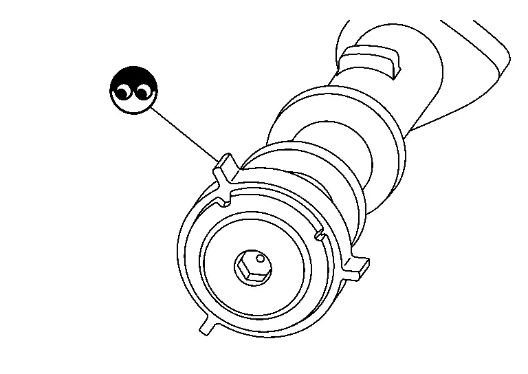
CHECK ENGINE OIL PRESSURE CONTROL SOLENOID VALVE-II
-
Remove engine oil pressure control solenoid valve. Refer to Exploded View.
-
Provide 12 V DC between engine oil pressure control solenoid valve terminals 1 and 2, and then interrupt it. Make sure that the plunger moves as shown in the figure.
CAUTION:
Do not apply 12 V DC continuously for 5 seconds or more. Doing so may result in damage to the coil in engine oil pressure control solenoid valve.
 NOTE:
NOTE:
Always replace O-ring when engine oil pressure control solenoid valve is removed.
Is the inspection result normal?
YES>>INSPECTION END
NO>>Replace engine oil pressure control solenoid valve. Refer to Exploded View.
P06dd Variable Oil Pressure Valve Nissan Pathfinder SUV
DTC Description
DTC DETECTION LOGIC
| DTC |
CONSULT screen terms (Trouble diagnosis content) |
DTC detection condition | ||
| P06DD | 00 |
Engine oil pressure control (High pressure stuck diagnosis) |
Diagnosis condition |
A. Engine speed 1450 - 3000 rpm [engine oil temperature 30 °C (86 °F) ] B. Engine speed 2050 - 3000 rpm [engine oil temperature 50 °C (122 °F) ] C. Engine speed 2550 - 3000 rpm [engine oil temperature 80 °C (176 °F) ] |
| Signal (terminal) | — | |||
| Threshold | More than 2.1 V | |||
| Diagnosis delay time | 9 seconds | |||
POSSIBLE CAUSE
-
Engine oil pressure control solenoid valve
-
Foreign matter caughtat engine oil pressure control solenoid valve
-
Decrease in engine oil pressure
-
Decrease in engine oil level
-
Engine oil condition
-
EOP sensor
-
Cause of engine oil consumption
FAIL-SAFE
| Fail safe mode | Nissan Pathfinder Vehicle behavior | |||
| Others | Fixes engine oil pressure control solenoid valve in the high oil pressure control position | |||
DTC Confirmation Procedure
PERFORM DTC CONFIRMATION PROCEDURE
 With CONSULT
-
Ignition switch ON.
-
On CONSULT screen, select “ENGINE”>>“Data Monitor”.
-
Maintain the following conditions for at least 9 consecutive seconds.
| ENG SPEED |
A. Engine speed 1450 - 3000 rpm [engine oil temperature 30 °C (86 °F) ] B. Engine speed 2050 - 3000 rpm [engine oil temperature 50 °C (122 °F) ] C. Engine speed 2550 - 3000 rpm [engine oil temperature 80 °C (176 °F) ] |
|||
| COOLAN TEMP/S |
A. 30 °C (86 °F) B. 50 °C (122 °F) C. 80 °C (176 °F) |
|||
| Selector lever | P or N position | |||
| Driving location | Under low load | |||
Is DTC P06DD detected?
YES>>Refer to DTC Diagnosis Procedure.
NO>>INSPECTION END
DTC Diagnosis Procedure
CHECK ENGINE OIL LEVEL
Check engine oil level. Refer to Inspection.
Is the inspection result normal?
YES>>GO TO 2.
NO>>Repair or replace error-detected parts.
CHECK ENGINE OIL PRESSURE CONTROL SOLENOID VALVE
Check the engine oil pressure control solenoid valve. Refer to Component Inspection (Engine Oil Pressure Control Solenoid Valve).
Is the inspection result normal?
YES>>GO TO 3.
NO>>Replace engine oil pressure control solenoid valve. Refer to Removal and Installation.
CHECK EOP SENSOR
Check EOP sensor. Refer to Component Inspection.
Is the inspection result normal?
YES>>INSPECTION END
NO>>Repair or replace error-detected parts.
P06e6 Internal Control Module Nissan Pathfinder 2022
DTC Description
DESCRIPTION
ECM supplies a voltage of 5 V to some of the sensors systematically divided into 3 groups, respectively. Accordingly, when a short circuit develops in a sensor power source, a malfunction may occur simultaneously in the sensors belonging to the same group as the short-circuited sensor.
Sensor power supply 1
-
APP sensor 1
-
Crankshaft position sensor 1
-
Exhaust camshaft position sensor (bank 1)
-
Throttle position sensor
-
Mass air flow sensor
-
Intake camshaft position sensor (bank 1)
-
Engine oil pressure sensor
 NOTE:
NOTE:
If sensor power supply 1 circuit is malfunctioning, DTC P0643 is displayed.
Sensor power supply 2
-
APP sensor 2
-
Intake camshaft position sensor (bank2)
-
Refrigerant pressure sensor
-
Crankshaft position sensor 2
-
Exhaust camshaft position sensor (bank 2)
-
Fuel rail pressure sensor
Sensor power supply 3
-
EVAP control system pressure sensor
DTC DETECTION LOGIC
| DTC |
CONSULT screen terms (Trouble diagnosis content) |
DTC detection condition | ||
| P06E6 | 11 |
Internal control module (Internal Control Module Knock/Combustion Vibration Sensor Processor 1 Performance) |
Diagnosis condition | Ignition switch ON |
| Signal | ― | |||
| 12 | Threshold | Malfunction in the sensor power supply voltage of ECM internal circuit | ||
| Diagnosis delay time | 5 seconds | |||
POSSIBLE CAUSE
-
Harness or connectors (EVAP control system pressure sensor is shorted. )
-
EVAP control system pressure sensor
FAIL-SAFE
Not applicable
DTC CONFIRMATION PROCEDURE
PRECONDITIONING
TESTING CONDITION:
Before performing the following procedure, confirm that battery voltage is 11 V or more with ignition switch ON.
>>
GO TO 2.
PERFORM DTC CONFIRMATION PROCEDURE
-
Turn ignition switch ON and wait at least 10 second.
-
Turn ignition switch OFF and wait at least 10 seconds.
-
Repeat step 1 and 2 for 2 times.
-
Turn ignition switch ON.
-
Check the DTC.
Is the DTC detected?
YES>>Proceed to DTC Diagnosis Procedure.
NO-1>>To check malfunction symptom before repair: Refer to Intermittent Incident.
NO-2>>Confirmation after repair: INSPECTION END
DTC Diagnosis Procedure
CHECK ECM POWER SUPPLY AND GROUND CIRCUIT
Perform trouble diagnosis for ECM power supply and ground circuit. Refer to Diagnosis Procedure.
Is the inspection result normal?
YES>>GO TO 2.
NO>>Repair or replace error-detected parts.
CHECK EVAP CONTROL SYSTEM PRESSURE SENSOR POWER SUPPLY CIRCUIT-1
-
Turn ignition switch OFF.
-
Disconnect EVAP control system pressure sensor harness connector.
-
Turn ignition switch ON.
-
Check the voltage between EVAP control system pressure sensor harness connector and ground.
+ - Voltage
(Approx.)EVAP control system pressure sensor Connector Terminal B36 3 Ground 5V
Is the inspection result normal?
YES>>GO TO 5.
NO>>GO TO 3.
CHECK EVAP CONTROL SYSTEM PRESSURE SENSOR SUPPLY CIRCUIT-2
-
Turn ignition switch OFF.
-
Disconnect ECM harness connector.
-
Check the continuity between EVAP control system pressure sensor harness connector and ECM harness connector.
+ + Continuity EVAP control system pressure sensor ECM Connector Terminal Connector Terminal B36 3 E32 177 Existed
Is the inspection result normal?
YES>>GO TO 4.
NO>>Repair open circuit.
CHECK SENSOR POWER SUPPLY 3 CIRCUIT
-
Disconnect following sensors harness connector.
-
Check harness for short to power and short to ground, between the following terminals.
| ECM | Sensor | |||
|---|---|---|---|---|
| Connector | Terminal | Name | Connector | Terminal |
| B36 | 3 | EVAP control system pressure sensor | E32 | 177 |
Is the inspection result normal?
YES>>GO TO 5.
NO>>Repair short to ground or short to power in harness or connectors.
CHECK INTERMITTENT INCIDENT
Check intermittent incident. Refer to Intermittent Incident.
Is the inspection result normal?
YES>>GO TO 6.
NO>>Repair or replace error-detected parts.
PERFORM DTC CONFIRMATION PROCEDURE
-
Turn ignition switch ON.
-
Erase DTC.
-
Perform DTC confirmation procedure. Refer to DTC Description.
Is the 1st trip DTC P06E6 displayed again?
YES>>Replace ECM. Refer to Removal and Installation.
NO>>INSPECTION END
P0719 Brake Pedal Switch B Nissan Pathfinder 2026
DTC Description
DTC DETECTION LOGIC
| DTC |
CONSULT screen terms (Trouble diagnosis content) |
DTC detection condition | ||
| P0719 | 00 |
Brake pedal switch B (Brake Switch "B" Circuit Low) |
Diagnosis condition |
|
| Signal (terminal) | CAN communication signal | |||
| Threshold | The stop lamp switch is released until 2 seconds have passed after the Nissan Pathfinder vehicle has stopped when the diagnosis condition is established. Malfunction is confirmed when the above condition is established 5 times. | |||
| Diagnosis delay time | — | |||
POSSIBLE CAUSE
-
Harness or connectors
(Stop lamp switch circuit is open.)
-
Stop lamp switch (BCM)
FAIL-SAFE
Not applicable
CONFIRMATION PROCEDURE
PRECONDITIONING
If DTC Confirmation Procedure has been previously conducted, always perform the following procedure before conducting the next test.
-
Turn ignition switch OFF and wait at least 10 seconds.
-
Turn ignition switch ON.
-
Turn ignition switch OFF and wait at least 10 seconds.
TEST CONDITION:
Before performing the following procedure, confirm that battery voltage is more than 11 V at ignition switch ON.
>>
GO TO 2.
PERFORM DTC CONFIRMATION PROCEDURE
-
Turn ignition switch ON and wait at least 2 seconds.
-
Repeat the following step 5 times.
-
Drive the Nissan Pathfinder vehicle and accelerate to 48 km/h (30 MPH).
-
Decelerate from 48 km/h (30 MPH) to 0 km/h (0 MPH) within 7 seconds.
-
Stop the Nissan Pathfinder vehicle for 2 seconds or more.
CAUTION:
Always drive vehicle at a safe speed.
 NOTE:
NOTE:
This procedure may be conducted with the drive wheels lifted in the shop or by driving the Nissan Pathfinder vehicle. If a road test is expected to be easier, it is unnecessary to lift the vehicle.
-
-
Check DTC.
Is DTC P0719 detected?
YES>>Refer to DTC Diagnosis Procedure.
NO-1>>To check malfunction symptom before repair: Refer to Intermittent Incident.
NO-2>>Confirmation after repair: INSPECTION END
DTC Diagnosis Procedure
PERFORM BCM DIAGNOSIS
Perform BCM diagnosis. Refer to DTC Index.
Is the inspection result normal?
YES>>GO TO 2.
NO>>Repair or replace error-detected parts.
REPLACE ECM
Replace ECM. Refer to Removal and Installation.
>>
INSPECTION END
P0850 Pnp Switch Nissan Pathfinder
DTC Description
When the selector lever position is P or N, park/neutral position (PNP) signal from the TCM is sent to ECM.
ECM detects the position because the continuity of the line (the ON signal) exists.
DTC DETECTION LOGIC
| DTC |
CONSULT screen terms (Trouble diagnosis content) |
DTC detection condition | ||
| P0850 | 00 |
P-N POS SW/CIRCUIT (Park/Neutral switch input circuit) |
Diagnosis condition | — |
| Signal (terminal) | Park/neutral position (PNP) signal | |||
| Threshold | The signal of the park/neutral position (PNP) signal does not change during driving after the engine is started | |||
| Diagnosis delay time | — | |||
POSSIBLE CAUSE
-
Harness or connectors
-
Transmission range switch
-
TCM
-
Electric shift control module
FAIL-SAFE
Not applicable
DTC Confirmation Procedure
CHECK DTC PRIORITY
If DTC P0850 is displayed with DTC UXXXX, first perform the trouble diagnosis for DTC UXXXX.
Is applicable DTC detected?
YES>>Perform diagnosis of applicable. Refer to DTC Index
NO>>GO TO 2.
PRECONDITIONING
If DTC Confirmation Procedure has been previously conducted, always perform the following procedure before conducting the next test.
-
Turn ignition switch OFF and wait at least 10 seconds.
-
Turn ignition switch ON.
-
Turn ignition switch OFF and wait at least 10 seconds.
>>
GO TO 3.
CHECK PNP SIGNAL
 With CONSULT
-
Turn ignition switch ON.
-
On CONSULT screen, select “ENGINE”>>“Data Monitor”>>“P/N POSI SW”.
-
Check the “P/N POSI SW” signal under the following conditions.
Position (Selector lever) Known-good signal N or P position ON Except above position OFF
Is the inspection result normal?
YES>>GO TO 4.
NO>>Proceed to Diagnosis Procedure.
PERFORM DTC CONFIRMATION PROCEDURE
 With CONSULT
-
On CONSULT screen, select “ENGINE”>>“Data Monitor”.
-
Start engine and warm it up to normal operating temperature.
-
Maintain the following conditions for at least 50 consecutive seconds.
CAUTION:
Always drive Nissan Pathfinder vehicle at a safe speed.
ENG SPEED 950 – 6,375 rpm COOLAN TEMP/S More than 66°C (151°F) B/FUEL SCHDL 3.0 – 31.8 msec VHCL SPEED SE More than 64 km/h (40 mph) Selector lever Suitable position -
Check 1st trip DTC.
Is DTC P0850 detected?
YES>>Proceed to Diagnosis Procedure.
NO-1>>To check malfunction symptom before repair: Refer to Intermittent Incident.
NO-2>>Confirmation after repair: INSPECTION END
Diagnosis Procedure
CHECK DTC PRIORITY
If DTC P0850 is displayed with DTC UXXXX, first perform the trouble diagnosis for DTC UXXXX.
Is applicable DTC detected?
YES>>Perform diagnosis of applicable. Refer to DTC Index
NO>>GO TO 2.
CHECK DTC WITH TCM
Check DTC with TCM. Refer to DTC Index.
Is the inspection result normal?
YES>>GO TO 3.
NO>>Perform trouble shooting relevant to DTC indicated.
CHECK DTC WITH ELECTRIC SHIFT CONTROL MODULE
Check DTC with electric shift control module. Refer to DTC Index.
Is the inspection result normal?
YES>>Check intermittent incident. Refer to Intermittent Incident.
NO>>Perform trouble shooting relevant to DTC indicated.
P1140 Intake Camshaft Position Sensor Nissan Pathfinder R53
DTC Description
DTC DETECTION LOGIC
| DTC |
CONSULT screen terms (Trouble diagnosis content) |
DTC detection condition | |||
| P1140 | 00 |
INTK TIM S/CIRC-B1 (Intake timing sensor circuit bank 1) |
A | Diagnosis condition | Engine running at idle |
| Signal (terminal) | Intake camshaft position sensor (bank 1) signal | ||||
| Threshold | Intake camshaft position sensor signal is not inputted to ECM | ||||
| Diagnosis delay time | 1 second or more | ||||
| B | Diagnosis condition | Engine running at idle | |||
| Signal (terminal) | Intake camshaft position sensor (bank 1) signal | ||||
| Threshold | Intake camshaft position sensor signal is inappropriate or partly missing | ||||
| Diagnosis delay time | 1 second or more | ||||
POSSIBLE CAUSE
-
Harness or connectors [Intake camshaft position sensor (bank 1) circuit is open or shorted.]
-
Intake camshaft position sensor (bank 1)
-
Intake camshaft (bank 1) (sensor rotor)
FAIL-SAFE
Not applicable
DTC CONFIRMATION PROCEDURE
PRECONDITIONING
If DTC Confirmation Procedure has been previously conducted, always perform the following procedure before conducting the next test.
-
Turn ignition switch OFF and wait at least 10 seconds.
-
Turn ignition switch ON.
-
Turn ignition switch OFF and wait at least 10 seconds.
>>
GO TO 2.
PERFORM DTC CONFIRMATION PROCEDURE
-
Start the engine and let it idle at least 10 seconds.
-
Check DTC.
Is DTC P1140 detected?
YES>>Refer to DTC Diagnosis Procedure.
NO-1>>To check malfunction symptom before repair: Refer to Intermittent Incident.
NO-2>>Confirmation after repair: INSPECTION END
DTC Diagnosis Procedure
CHECK INTAKE CAMSHAFT POSITION (CMP) SENSOR POWER SUPPLY
-
Turn ignition switch OFF.
-
Disconnect CMP sensor (bank 1) harness connector.
-
Turn ignition switch ON.
-
Check the voltage between intake CMP sensor (bank 1) harness connector and ground.
+ − Voltage
(Approx.)Intake CMP sensor (bank 1) Connector Terminal F113 1 Ground 5 V
Is the inspection result normal?
YES>>GO TO 3.
NO>>GO TO 2.
CHECK INTAKE CMP SENSOR (BANK 1) POWER SUPPLY CIRCUIT
-
Turn ignition switch OFF
-
Disconnect ECM harness connector.
-
Check the continuity between intake CMP sensor (bank 1) harness connector and ECM harness connector.
Intake CMP sensor (bank 1) ECM Continuity Connector Terminal Connector Terminal F113 1 F78 40 Existed -
Also check harness for short to power and short to ground.
Is the inspection result normal?
YES>>Perform the trouble diagnosis for ECM power supply circuit.
NO>>Repair or replace error-detected parts.
CHECK INTAKE CMP SENSOR (BANK 1) GROUND CIRCUIT
-
Turn ignition switch OFF.
-
Disconnect ECM harness connector.
-
Check the continuity between intake CMP sensor (bank 1) harness connector and ECM harness connector.
Intake CMP sensor (bank 1) ECM Continuity Connector Terminal Connector Terminal F113 2 F78 27 Existed -
Also check harness for short to power.
Is the inspection result normal?
YES>>GO TO 4.
NO>>Repair or replace error-detected parts.
CHECK INTAKE CMP SENSOR (BANK 1) INPUT SIGNAL CIRCUIT
-
Check the continuity between intake CMP sensor (bank 1) harness connector and ECM harness connector.
Intake CMP sensor (bank 1) ECM Continuity Connector Terminal Connector Terminal F113 3 F78 36 Existed -
Also check harness for short to power and short to ground.
Is the inspection result normal?
YES>>GO TO 5.
NO>>Repair or replace error-detected parts.
CHECK INTAKE CMP SENSOR (BANK 1)
Check intake CMP sensor (bank 1). Refer to Component Inspection.
Is the inspection result normal?
YES>>GO TO 6.
NO>>Replace intake CMP sensor (bank 1). Refer to Exploded View.
CHECK INTAKE CAMSHAFT (BANK 1)
Check the following items:
-
Accumulation of debris to the signal plate intake camshaft (bank 1) rear end
-
Chipping signal plate of camshaft rear end
Is the inspection result normal?
YES>>INSPECTION END
NO>>Remove debris and clean the signal plate of the camshaft rear end or replace the camshaft. Refer to Exploded View.
P1148 Closed Loop Control Nissan Pathfinder SUV
DTC Description
DTC DETECTION LOGIC
| DTC |
CONSULT screen terms (Trouble diagnosis content) |
DTC detection condition | ||
| P1148 | 00 |
CLOSED LOOP-B1 (Closed loop bank 1) |
Diagnosis condition | — |
| Signal (terminal) | — | |||
| Threshold | The closed loop control function for bank 1 does not operate even when Nissan Pathfinder vehicle is being driven in the specified condition | |||
| Diagnosis delay time | — | |||
POSSIBLE CAUSE
-
Harness or connectors [A/F sensor 1 (bank1) circuit is open or shorted.]
-
A/F sensor 1 (bank 1)
-
A/F sensor 1 (bank 1) heater
FAIL-SAFE
Not applicable
DTC Confirmation Procedure
CHECK DTC PRIORITY
If DTC P1148 is displayed with DTC for A/F sensor 1, first perform the confirmation procedure (trouble diagnosis) of DTC corresponding to A/F sensor 1.
Is applicable DTC detected?
YES>>Proceed to Diagnosis Procedure.
NO-1>>To check malfunction symptom before repair: Refer to Intermittent Incident.
NO-2>>Confirmation after repair: INSPECTION END
Diagnosis Procedure
CHECK DTC PRIORITY
If DTC P1148 is displayed with DTC for A/F sensor 1, first perform the confirmation procedure (trouble diagnosis) of DTC corresponding to A/F sensor 1.
Is applicable DTC detected?
YES>>Perform diagnosis of applicable. Refer to DTC Index.
NO>>INSPECTION END
P1197 Out of Gas Nissan Pathfinder R53
DTC Description
This diagnosis result is detected when the fuel level of the fuel tank is extremely low and the engine does not run normally.
DTC DETECTION LOGIC
| DTC |
CONSULT screen terms (Trouble diagnosis content) |
DTC detection condition | ||
| P1197 | 00 |
FUEL RUN OUT (Out of gas) |
Diagnosis condition | — |
| Signal (terminal) | — | |||
| Threshold |
|
|||
| Diagnosis delay time | 5 seconds or more | |||
POSSIBLE CAUSE
-
Out of gas
-
Harness or connectors (Low pressure fuel pump circuit is open or shorted.)
-
Low pressure fuel pump
-
Harness or connectors (High pressure fuel pump circuit is shorted.)
-
Fuel pressure regulator
-
Low pressure fuel system
-
High pressure fuel pump
-
High pressure fuel pump power supply circuit
-
High pressure fuel system
-
Fuel rail pressure sensor
-
Disconnection of the fuel hose
FAIL-SAFE
| Fail safe mode | Nissan Pathfinder Vehicle behavior | |
|---|---|---|
| Device fix mode |
|
|
DTC Confirmation Procedure
PRECONDITIONING
-
Turn ignition switch OFF and wait at least 10 seconds.
-
Turn ignition switch ON.
-
Turn ignition switch OFF and wait at least 10 seconds.
TESTING CONDITION:
Before performing the following procedure, confirm that battery voltage is 11 V or more at idle.
>>
GO TO 2.
PERFORM DTC CONFIRMATION PROCEDURE-I
Start the engine.
Does the engine start?
YES>>GO TO 3.
NO>>Proceed to Diagnosis Procedure.
PERFORM DTC CONFIRMATION PROCEDURE-II
-
Warm up the engine to the normal operating temperature.
 NOTE:
NOTE:
For best results, warm up the engine until “COOLAN TEMP/S” on “DATA MONITOR” mode of “ENGINE” reaches at least 70°C (158°F).
-
Keep the engine speed at 3,500 rpm for 5 seconds and let it idle at least 60 seconds.
-
Check the 1st trip DTC.
 NOTE:
NOTE:
If the fuel tank has sufficient fuel, this diagnosis result may not be detected.
Is DTC P1197 detected?
YES>>Proceed to Diagnosis Procedure.
NO-1>>To check malfunction symptom before repair: Refer to Intermittent Incident.
NO-2>>Confirmation after repair: INSPECTION END
Diagnosis Procedure
REFUEL THE VEHICLE
-
Refuel 10 liter (10 US qt, 8 imp qt).
CAUTION:
Never refuel more than 10 liter.
-
Start the engine and keep the engine speed at 3,000 rpm for 30 seconds.
 NOTE:
NOTE:
For best results, warm up the engine until “COOLAN TEMP/S” on “DATA MONITOR” mode of “ENGINE” reaches at least 70°C (158°F).
-
Turn ignition switch OFF and wait at least 10 seconds.
-
Turn ignition switch ON.
-
Turn ignition switch OFF and wait at least 10 seconds.
-
Turn ignition switch ON.
-
Erase the DTC.
-
Start the engine and let it idle at least 60 seconds.
-
Perform DTC confirmation procedure again. Refer to DTC Description.
Is DTC P1197 detected?
YES>>GO TO 2.
NO>>INSPECTION END
CHECK LOW PRESSURE FUEL PUMP
Check low pressure fuel pump. Refer to Component Function Check.
Is inspection result normal?
YES>>GO TO 3.
NO>>Repair or replace error-detected parts.
CHECK HIGH PRESSURE FUEL PUMP CONTROL CIRCUIT
Check high pressure fuel pump control circuit. Refer to Component Function Check.
Is inspection result normal?
YES>>GO TO 4.
NO>>Repair or replace error-detected parts.
CHECK ECM POWER SUPPLY CIRCUIT
Check ECM power supply circuit. Refer to Diagnosis Procedure.
Is inspection result normal?
YES>>Check the fuel hose for disconnection and looseness.
NO>>Repair or replace error-detected parts.
P119a Fuel Rail Pressure Sensor Nissan Pathfinder SUV
DTC Description
DTC DETECTION LOGIC
| DTC |
CONSULT screen terms (Trouble diagnosis content) |
DTC detection condition | ||
| P119A | 00 |
FUEL PRESSURE SENSOR (Fuel pressure sensor) |
Diagnosis condition |
|
| Signal (terminal) | Fuel rail pressure sensor signal | |||
| Threshold | Fuel rail pressure is less than 1.0 MPa (10.2 kg/cm2, 145 psi) (calculated by ECM) | |||
| Diagnosis delay time | — | |||
POSSIBLE CAUSE
-
Harness or connectors
-
The fuel rail pressure sensor circuit is open or shorted.
-
Sensor power supply 2 is shorted.
-
-
Fuel rail pressure sensor
FAIL-SAFE
| Fail safe mode | Nissan Pathfinder Vehicle behavior | |
|---|---|---|
| Traveling control mode | Accelerator angle variation control |
ECM controls the accelerator pedal depression speed to make it slower than actual speed. This causes a drop in accelerating performance and encourages the driver to repair malfunction. ECM does not control the accelerator pedal releasing speed.
|
| Combustion control mode | Stratified charge combustion control at starting | No stratified charge combustion at starting (cold start). |
 NOTE:
NOTE: DTC Confirmation Procedure
PRECONDITIONING-I
If DTC Confirmation Procedure is previously conducted, always perform the following procedure before conducting the next test.
-
Turn ignition switch OFF and wait at least 10 seconds.
-
Turn ignition switch ON.
-
Turn ignition switch OFF and wait at least 10 seconds.
TESTING CONDITION:
Before performing the following procedure, check that battery voltage is 9 V or more with ignition switch ON.
>>
GO TO 2.
PRECONDITIONING-II
 NOTE:
NOTE:
-
When it is certain that the previous driving is performed with the engine warmed up, the next steps can be performed.
-
When it is difficult to satisfy the conditions, performing Component Function Check can identify the presence or absence of malfunction in the part/system that may result in a possible cause of this DTC. (Perform DTC Confirmation Procedure as much as possible.)
-
Start the engine and warm it up until engine coolant temperature reaches 70°C (158°F) or more.
-
Stop the engine and leave the Nissan Pathfinder vehicle in a cool place (soak the engine) until the engine coolant temperature reaches 35°C (95°F) or less.
CAUTION:
-
The difference between air temperature and engine coolant temperature must be 5°C (9°F) or less.
-
Never turn ignition switch ON during soak the engine.
Are the conditions satisfied?
YES>>
GO TO 4.
NO>>
GO TO 3.
COMPONENT FUNCTION CHECK
 With CONSULT
-
Turn ignition switch OFF.
-
Start the engine.
-
On CONSULT screen, select “ENGINE”>>“Data Monitor”.
-
Check the value of “FUEL PRES SEN V” under the following conditions.
Monitor Item Condition Values/Status FUEL PRES SEN V Engine speed: Idle 1.120 – 1.310 V Engine speed: Revving engine from idle to 4,000 rpm quickly 1.120 – 2.900 V
 Without CONSULT
-
Turn ignition switch OFF.
-
Start the engine.
-
Check fuel rail pressure sensor signal voltage.
| ECM | Condition | Voltage | ||
|---|---|---|---|---|
| Connector | + | − | ||
| Terminal | ||||
| F78 | 47 | 85 | Engine speed: Idle | 1.12 – 1.31 V |
| Engine speed: Revving engine from idle to 4,000 rpm quickly | 1.12 – 2.90 V | |||
Is the inspection result normal?
YES-1>>
To check malfunction symptom before repair: Refer to Intermittent Incident.
YES-2>>
Confirmation after repair: INSPECTION END
NO>>
Proceed to Diagnosis Procedure.
PERFORM DTC CONFIRMATION PROCEDURE-I
 With CONSULT
-
Turn ignition switch ON (engine stopped).
-
On CONSULT screen, select “ENGINE”>>“Data Monitor”>>“COOLAN TEMP/S” and “INT/A TEMP SE”.
-
Check that the indicated value of “COOLAN TEMP/S” is less than 35°C (95°F).
-
Check that the difference between “INT/A TEMP SE” and “COOLAN TEMP/S” is 5°C (41°F) or less.
-
Check “Self-diagnostic result” of “ENGINE”.
Is DTC P119A detected?
YES>>
Proceed to Diagnosis Procedure.
NO-1>>
Conditions satisfied: GO TO 5.
NO-2>>
Conditions not satisfied: GO TO 2.
PERFORM DTC CONFIRMATION PROCEDURE-II
-
Start the engine (or cranking) at least 1 second.
-
Check “Self-diagnostic result” of “ENGINE”.
Is DTC P119A detected?
YES>>
Proceed to Diagnosis Procedure.
NO-1>>
To check malfunction symptom before repair: Refer to Intermittent Incident.
NO-2>>
Confirmation after repair: INSPECTION END
Diagnosis Procedure
 NOTE:
NOTE:
Turning the ignition switch ON with FRP sensor harness connector disconnected causes ECM to detect DTC P0190. Be sure to erase the DTC when the diagnosis procedure.
CHECK FUEL RAIL PRESSURE (FRP) SENSOR POWER SUPPLY-I
-
Turn ignition switch OFF.
-
Disconnect FRP sensor connector.
-
Turn ignition switch ON.
-
Check the voltage between FRP sensor harness connector terminals.
FRP sensor Voltage
(Approx.)Connector + − terminal F97 3 1 5 V
Inspection result normal?
YES>>
GO TO 7.
NO>>
GO TO 2.
CHECK FRP SENSOR POWER SUPPLY-II
Check the voltage between FRP sensor harness connector and the ground.
| + | − |
Voltage (Approx.) |
|
|---|---|---|---|
| FRP sensor | |||
| Connector | Terminal | ||
| F97 | 3 | Ground | 5 V |
Is inspection result normal?
YES>>
GO TO 5.
NO>>
GO TO 3.
CHECK FRP SENSOR POWER SUPPLY CIRCUIT
-
Turn ignition switch OFF.
-
Disconnect ECM harness connector.
-
Check the continuity between FRP sensor harness connector and ECM harness connector.
FRP sensor ECM Continuity Connector Terminal Connector Terminal F97 3 F78 66 Existed -
Also check harness for short to power and short to ground.
Is inspection result normal?
YES>>
GO TO 4.
NO>>
Repair or replace error-detected parts.
CHECK SENSOR POWER SUPPLY 2 CIRCUIT
Perform Diagnosis Procedure.
Is inspection result normal?
YES>>
Perform the trouble diagnosis for ECM power supply circuit. Refer to Diagnosis Procedure.
NO>>
Repair or replace error-detected parts.
CHECK FRP SENSOR GROUND CIRCUIT
-
Turn ignition switch OFF.
-
Disconnect ECM harness connector.
-
Check the continuity between FRP sensor harness connector and ECM harness connector.
FRP sensor ECM Continuity Connector Terminal Connector Terminal F97 1 F78 85 Existed -
Also check harness for short to power.
Is inspection result normal?
YES>>
GO TO 6.
NO>>
Repair or replace error-detected parts.
CHECK ECM GROUND CIRCUIT
-
Check the continuity between ECM harness connector and ground.
ECM — Continuity Connector Terminal F78 3 Ground Existed F79 87 E32 199 201 204 -
Also check harness for short to power.
Is the inspection result normal?
YES>>
INSPECTION END
NO>>
Repair or replace error-detected parts.
CHECK FRP SENSOR SIGNAL CIRCUIT
-
Turn ignition switch OFF.
-
Disconnect ECM harness connector.
-
Check the continuity between FRP sensor harness connector and ECM harness connector.
FRP sensor ECM Continuity Connector Terminal Connector Terminal F97 2 F78 47 Existed -
Also check harness for short to power and short to ground.
Is inspection result normal?
YES>>
GO TO 8.
NO>>
Repair or replace error-detected parts.
CHECK FRP SENSOR
Check the FRP sensor. Refer to Component Inspection (Fuel Rail Pressure Sensor).
Is inspection result normal?
YES>>
INSPECTION END
NO>>
Repair or replace error-detected parts.
Component Inspection (Fuel Rail Pressure Sensor)
CHECK FRP SENSOR
 With CONSULT
-
Turn ignition switch OFF.
-
Reconnect harness connector disconnected.
-
Start engine.
-
On CONSULT screen, select “ENGINE”>>“Data Monitor”.
-
Check that the “FUEL PRES SEN V” indication.
Monitor Item Condition Values/Status FUEL PRES SEN V Engine speed: Idle 1.120 – 1.310 V Engine speed: Revving engine from idle to 4,000 rpm quickly 1.120 – 2.900 V
 Without CONSULT
-
Turn ignition switch OFF.
-
Reconnect harness connector disconnected.
-
Start the engine.
-
Check FRP sensor signal voltage.
| ECM | Condition | Voltage | ||
|---|---|---|---|---|
| Connector | + | − | ||
| Terminal | ||||
| F78 | 47 | 85 | Engine speed: Idle | 1.12 – 1.31 V |
| Engine speed: Revving engine from idle to 4,000 rpm quickly | 1.12 – 2.90 V | |||
Is the inspection result normal?
YES>>
INSPECTION END
NO>>
Replace FRP sensor. Refer to Exploded View.
P1217 Engine Over Temperature Nissan Pathfinder
DTC Description
If the cooling fan or another component in the cooling system malfunctions, engine coolant temperature will rise.
When the engine coolant temperature reaches an abnormally high temperature condition, a malfunction is indicated.
DTC DETECTION LOGIC
| DTC |
CONSULT screen terms (Trouble diagnosis content) |
DTC detection condition | ||
| P1217 | 00 |
ENG OVER TEMP [Engine over temperature (Overheat)] |
Diagnosis condition | — |
| Signal (terminal) | — | |||
| Threshold |
|
|||
| Diagnosis delay time | — | |||
CAUTION:
When a malfunction is indicated, always replace the coolant. Also, replace the engine oil.
-
Fill radiator with coolant up to specified level with a filling speed of 2 liters per minute. Always use coolant with the proper mixture ratio. Refer to Engine Coolant Mixture Ratio.
-
After refilling coolant, run engine to ensure that no water-flow noise is emitted.
POSSIBLE CAUSE
-
Harness or connectors (Cooling fan circuit is open or shorted.)
-
IPDM E/R
-
Cooling fan control module
-
Cooling fan motor
-
Radiator hose
-
Radiator
-
Radiator cap
-
Water pump
-
Thermostat
-
Engine coolant temperature sensor
FAIL-SAFE
Not applicable
DTC Confirmation Procedure
CHECK DTC PRIORITY
If DTC P1217 is displayed with DTC UXXXX or P0607, first perform the confirmation procedure (trouble diagnosis) for DTC UXXXX or P0607.
Is DTC UXXXX or P0607 detected?
YES>>
Perform diagnosis of applicable.
-
DTC UXXXX: Refer to DTC Index.
-
DTC P0607: Refer to DTC Description.
NO>>
GO TO 2.
PERFORM COMPONENT FUNCTION CHECK-I
WARNING:
Never remove the radiator cap when the engine is hot. Serious burns could be caused by high pressure fluid escaping from the radiator.
Wrap a thick cloth around cap. Carefully remove the cap by turning it a quarter turn to allow built-up pressure to escape. Then turn the cap all the way off.
 NOTE:
NOTE:
Use component function check to check the overall function of the cooling fan. During this check, a DTC might not be confirmed.
Check the coolant level in the reservoir tank and radiator.
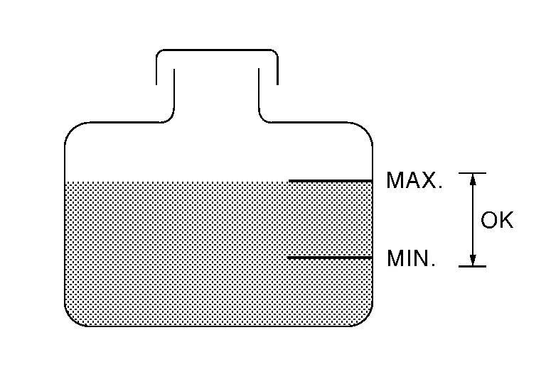
Allow engine to cool before checking coolant level.
Is the coolant level in the reservoir tank and/or radiator below the proper range?
YES>>
Proceed to Diagnosis Procedure.
NO>>
GO TO 3.
PERFORM COMPONENT FUNCTION CHECK-II
Confirm whether customer filled the coolant or not.
Did customer fill the coolant?
YES>>
Proceed to Diagnosis Procedure.
NO>>
GO TO 4.
PERFORM COMPONENT FUNCTION CHECK-III
 With CONSULT
-
Turn ignition switch ON.
-
Perform “FAN DUTY CONTROL” in “Active Test” mode of “ENGINE”.
-
Make sure that cooling fan speed varies according to the percentage.
 Without CONSULT
Perform IPDM E/R auto active test and check cooling fan motors operation, refer to CONSULT Function (IPDM E/R).
Is the inspection result normal?
YES-1>>
To check malfunction symptom before repair: Refer to Intermittent Incident.
YES-2>>
Confirmation after repair: INSPECTION END
NO>>
Proceed to Diagnosis Procedure.
Diagnosis Procedure
CHECK DTC PRIORITY
If DTC P1217 is displayed with DTC UXXXX or P0607, first perform the confirmation procedure (trouble diagnosis) for DTC UXXXX or P0607.
Is DTC UXXXX or P0607 detected?
YES>>
Perform diagnosis of applicable.
-
DTC UXXXX: Refer to DTC Index.
-
DTC P0607: Refer to DTC Description.
NO>>
GO TO 2.
CHECK COOLING FAN OPERATION
 With CONSULT
-
Turn ignition switch ON.
-
Perform “FAN DUTY CONTROL” in “Active Test” mode of “ENGINE”.
-
Make sure that cooling fan speed varies according to the percentage.
 Without CONSULT
-
Perform IPDM E/R auto active test and check cooling fan motors operation, refer to CONSULT Function (IPDM E/R).
-
Make sure that cooling fan operates.
Is the inspection result normal?
YES>>
GO TO 3.
NO>>
Proceed to Diagnosis Procedure (Cooling Fan Motor).
CHECK COOLING SYSTEM FOR LEAK-I
Check cooling system for leak. Refer to System Inspection.
Is leakage detected?
YES>>
GO TO 4.
NO>>
GO TO 5.
CHECK COOLING SYSTEM FOR LEAK-II
Check the following for leak.
-
Hose
-
Radiator
-
Water pump
>>
Repair or replace malfunctioning part.
CHECK RADIATOR CAP
Check radiator cap. Refer to System Inspection.
Is the inspection result normal?
YES>>
GO TO 6.
NO>>
Replace radiator cap. Refer to Exploded View.
CHECK THERMOSTAT
Check thermostat. Refer to Removal and Installation.
Is the inspection result normal?
YES>>
GO TO 7.
NO>>
Replace thermostat assembly. Refer to Removal and Installation.
CHECK ENGINE COOLANT TEMPERATURE SENSOR
Check engine coolant temperature sensor. Refer to Component Inspection (Engine Coolant Temperature Sensor).
Is the inspection result normal?
YES>>
GO TO 8.
NO>>
Replace engine coolant temperature sensor. Refer to Exploded View.
OVERHEATING CAUSE ANALYSIS
If the cause cannot be isolated, check the Troubleshooting Chart.
>>
INSPECTION END

Nissan Pathfinder (R53) 2022-2026 Service Manual
Dtc/circuit Diagnosis (P06da Engine Oil Pressure Control Solenoid Valve ... P1217 Engine Over Temperature)
- P06da Engine Oil Pressure Control Solenoid Valve
- P06dd Variable Oil Pressure Valve
- P06e6 Internal Control Module
- P0719 Brake Pedal Switch B
- P0850 Pnp Switch
- P1140 Intake Camshaft Position Sensor
- P1148 Closed Loop Control
- P1197 Out of Gas
- P119a Fuel Rail Pressure Sensor
- P1217 Engine Over Temperature
Contact Us
Nissan Pathfinder Info Center
Email: info@nipathfinder.com
Phone: +1 (800) 123-4567
Address: 123 Pathfinder Blvd, Nashville, TN 37214, USA
Working Hours: Mon–Fri, 9:00 AM – 5:00 PM (EST)
