Nissan Pathfinder: Dtc/circuit Diagnosis (P0011 Intake Valve Timing Control ... P0111 Iat Sensor)
- P0011 Intake Valve Timing Control
- P0014 Evt Control
- P0030 A/f Sensor 1 Heater
- P0078 Evt Control Solenoid Valve
- P0087 Frp Control System ➤
- P00d2 Ho2s2 Heater
- P00fe Evap Control System
- P0101 Maf Sensor
- P0107 Barometric Pressure Sensor
- P0111 Iat Sensor
P0011 Intake Valve Timing Control Nissan Pathfinder 5th Gen
DTC Description
DTC DETECTION LOGIC
| DTC |
CONSULT screen terms (Trouble diagnosis content) |
DTC detection condition | |||
| P0011 | 00 |
INT/V TIM CONT-B1 [Intake valve timing control performance (bank 1)] |
A | Diagnosis condition |
|
| Signal (terminal) | — | ||||
| Threshold | During the advanced control of intake valve timing control, the angle difference between actual angle and target angle is 13 degrees or more | ||||
| Diagnosis delay time | 6 seconds | ||||
| B | Diagnosis condition |
|
|||
| Signal (terminal) | — | ||||
| Threshold | During the advanced control of intake valve timing control, the absolute difference between valve timing control reference position and base angle is 13 degrees or more | ||||
| Diagnosis delay time | 3 seconds | ||||
POSSIBLE CAUSE
Malfunction A
-
Electric intake valve timing (IVT) control actuator (bank 1)
-
Harness and connectors (Electric IVT control actuator (bank 1) motor control circuit is open or shorted.)
-
Foreign matter caught at the electric IVT control actuator (bank 1)
Malfunction B
-
Timing chain installation
-
Intake camshaft sprocket (bank 1) wear
FAIL-SAFE
| Fail safe mode | Nissan Pathfinder Vehicle behavior | |
|---|---|---|
| Device fix mode |
|
|
DTC Confirmation Procedure
PRECONDITIONING
If DTC Confirmation Procedure has been previously conducted, always perform the following procedure before conducting the next test.
-
Turn ignition switch OFF and wait at least 10 seconds.
-
Turn ignition switch ON.
-
Turn ignition switch OFF and wait at least 10 seconds.
TESTING CONDITION:
Before performing the following procedure, confirm that battery voltage is between 11 V and 16 V at idle.
>>
GO TO 2.
PERFORM DTC CONFIRMATION PROCEDURE-I
 With CONSULT
-
Turn ignition switch ON.
-
On CONSULT screen, select “ENGINE”>>“Data Monitor”.
-
Start engine and warm it up to the normal operating temperature.
-
Maintain the following conditions for at least 10 consecutive seconds. Hold the accelerator pedal as steady as possible.
ENG SPEED 1,200 – 2,000 rpm COOLAN TEMP/S More than 60°C (140°F) Selector lever P or N position -
Let engine idle for 10 seconds.
-
Check 1st trip DTC.
 With GST
Follow the procedure “With CONSULT” above.
Is DTC P0011 detected?
YES>>Proceed to Diagnosis Procedure.
NO>>GO TO 3.
PERFORM DTC CONFIRMATION PROCEDURE-II
 With CONSULT
-
Maintain the following conditions for at least 20 consecutive seconds.
ENG SPEED 1,200 – 3,175 rpm (A constant rotation is maintained.) COOLAN TEMP/S More than 64°C (147°F) Selector lever 1st or 2nd position Driving location Driving Nissan Pathfinder vehicle uphill
(Increased engine load will help maintain the driving conditions required for this test.)CAUTION:
Always drive at a safe speed.
-
Check 1st trip DTC.
 WITH GST
Follow the procedure “With CONSULT” above.
Is DTC P0011 detected?
YES>>Proceed to Diagnosis Procedure.
NO-1>>To check malfunction symptom before repair: Refer to Intermittent Incident.
NO-2>>Confirmation after repair: INSPECTION END
Diagnosis Procedure
TYPE A
CHECK ELECTRIC IVT CONTROL ACTUATOR (BANK 1) MOTOR CONTROL CIRCUIT
-
Turn ignition switch OFF.
-
Disconnect electric IVT control actuator (bank 1) harness connector and electric IVT control module harness connector.
-
Check the continuity between electric IVT control actuator (bank 1) harness connector and electric IVT control module harness connector.
Electric IVT control actuator (bank 1) Electric IVT control module Continuity Connector Terminal Connector Terminal F87 1 F99 117 Existed 2 114 3 119 -
Check harness for short to power and short to ground.
Is the inspection result normal?
YES>>Replace electric IVT control actuator (bank 1). Refer to Exploded View.
NO>>Repair or replace error-detected parts.
TYPE B
CHECK TIMING CHAIN INSTALLATION
Check service records for any recent repairs that may cause timing chain misaligned.
Are there any service records that may cause timing chain misaligned?
YES>>Check timing chain installation. Refer to Removal and Installation.
NO>>GO TO 2.
CHECK CAMSHAFT SPROCKET AND TIMING CHAIN
Check the following.
-
Visually check for chipping camshaft sprocket (bank 1) gear tooth.
-
timing chain tension and elongation.
Is the inspection result normal?
YES>>INSPECTION END
NO>>Repair or replace error-detected parts.
P0014 Evt Control Nissan Pathfinder 2026
DTC Description
DTC DETECTION LOGIC
| DTC |
CONSULT screen terms (Trouble diagnosis content) |
DTC detection condition | ||
| P0014 | 00 |
EXH/V TIM CONT-B1 (“B” camshaft position - timing over-advanced or system performance bank 1) |
Diagnosis condition |
|
| Signal (terminal) | — | |||
| Threshold | During the advanced control of exhaust valve timing control, the angle difference between actual angle and target angle is 13 degrees or more | |||
| Diagnosis delay time | 6 seconds or more | |||
POSSIBLE CAUSE
-
Crankshaft position sensor 1
-
Exhaust camshaft position sensor
-
Exhaust valve control solenoid valve
-
Accumulation of debris to the signal pick-up portion of the camshaft
-
Timing chain installation
-
Foreign matter caught in the oil groove for exhaust valve timing control
FAIL-SAFE
| Fail safe mode | Nissan Pathfinder Vehicle behavior | |
|---|---|---|
| Device fix mode |
|
|
DTC Confirmation Procedure
CHECK DTC PRIORITY
If DTC P0014 is displayed with DTC P0078, first perform the confirmation procedure (trouble diagnosis) for DTC P0078.
Is DTC P0078 detected?
YES>>
Perform diagnosis for P0078. Refer to DTC Description.
NO>>
GO TO 2.
PRECONDITIONING
If DTC Confirmation Procedure has been previously conducted, always perform the following procedure before conducting the next test.
-
Turn ignition switch OFF and wait at least 10 seconds.
-
Turn ignition switch ON.
-
Turn ignition switch OFF and wait at least 10 seconds.
TESTING CONDITION:
Before performing the following procedure, confirm that battery voltage is between 10 V and 16 V at idle.
>>
GO TO 3.
PERFORM DTC CONFIRMATION PROCEDURE-I
 With CONSULT
-
Turn ignition switch ON.
-
On CONSULT screen, select “ENGINE”>>“Data Monitor”.
-
Start engine and warm it up to the normal operating temperature.
-
Maintain the following conditions for at least 6 consecutive seconds. Hold the accelerator pedal as steady as possible.
ENG SPEED 1,200 – 2,000 rpm (A constant rotation is maintained.) COOLAN TEMP/S More than 60°C (140°F) Selector lever P or N position -
Let engine idle for 10 seconds.
-
Check 1st trip DTC.
 With GST
Follow the procedure “With CONSULT” above.
Is DTC P0014 detected?
YES>>
Proceed to Diagnosis Procedure.
NO>>
GO TO 4.
PERFORM DTC CONFIRMATION PROCEDURE-II
 With CONSULT
-
Maintain the following conditions for at least 20 consecutive seconds.
ENG SPEED 1,700 – 2,950 rpm (A constant rotation is maintained.) COOLAN TEMP/S More than 70°C (158°F) Selector lever D position Driving location uphill Driving Nissan Pathfinder vehicle uphill
(Increased engine load will help maintain the driving conditions required for this test.)CAUTION:
Always drive at a safe speed.
-
Check 1st trip DTC.
 With GST
Follow the procedure “With CONSULT” above.
Is DTC P0014 detected?
YES>>
Proceed to Diagnosis Procedure
NO-1>>
To check malfunction symptom before repair: Refer to Intermittent Incident.
NO-2>>
Confirmation after repair: INSPECTION END
Diagnosis Procedure
CHECK DTC PRIORITY
If DTC P0014 is displayed with DTC P0078, first perform the confirmation procedure (trouble diagnosis) for DTC P0078.
Is DTC P0078 detected?
YES>>
Perform diagnosis for P0078. Refer to DTC Description.
NO>>
GO TO 2.
CHECK OIL PRESSURE WARNING
-
Start engine.
-
Check oil pressure warning and confirm it is not displayed.

Is oil pressure warning displayed?
YES>>
Check the engine oil level. Refer to Inspection.
NO>>
GO TO 3.
CHECK EXHAUST VALVE TIMING CONTROL SOLENOID VALVE
Check the exhaust valve timing control solenoid valve. Refer to Component Inspection (Exhaust Valve Timing Control Solenoid Valve).
Is the inspection result normal?
YES>>
GO TO 4.
NO>>
Replace malfunctioning exhaust valve timing control solenoid valve. Refer to Exploded View.
CHECK CRANKSHAFT POSITION SENSOR 1
Check the crankshaft position sensor 1. Refer to Component Inspection.
Is the inspection result normal?
YES>>
GO TO 5.
NO>>
Replace crankshaft position sensor 1. Refer to Exploded View.
CHECK EXHAUST CAMSHAFT POSITION SENSOR
Check the exhaust camshaft position sensor. Refer to Component Inspection.
Is the inspection result normal?
YES>>
GO TO 6.
NO>>
Replace malfunctioning exhaust camshaft position sensor. Refer to Exploded View.
CHECK CAMSHAFT (EXH)
Check the following.
-
Accumulation of debris to the signal plate of camshaft rear end
-
Chipping signal plate of camshaft rear end
Is the inspection result normal?
YES>>
GO TO 7.
NO>>
Remove debris and clean the signal plate of camshaft rear end or replace camshaft. Refer to Removal and Installation.
CHECK TIMING CHAIN INSTALLATION
Check service records for any recent repairs that may cause timing chain misaligned.
Are there any service records that may cause timing chain misaligned?
YES>>
Check timing chain installation. Refer to Removal and Installation.
NO>>
GO TO 8.
CHECK LUBRICATION CIRCUIT
Refer to Inspection.
Is the inspection result normal?
YES>>
INSPECTION END.
NO>>
Clean lubrication line.
Component Inspection (Exhaust Valve Timing Control Solenoid Valve)
CHECK EXHAUST VALVE TIMING CONTROL SOLENOID VALVE-I
-
Turn ignition switch OFF.
-
Disconnect exhaust valve timing control solenoid valve harness connector.
-
Check resistance between exhaust valve timing control solenoid valve terminals as per the following.
Exhaust valve timing control solenoid valve Condition
Resistance Terminal 1 2 Temperature [°C (°F)] 20 (68) 7.0 – 7.8 Ω 1 Ground ∞Ω
(Continuity should not exist)2
Is the inspection result normal?
YES>>
GO TO 2.
NO>>
Replace malfunctioning exhaust valve timing control solenoid valve. Refer to Exploded View.
CHECK EXHAUST VALVE TIMING CONTROL SOLENOID VALVE-II
-
Remove exhaust valve timing control solenoid valve. Refer to Exploded View.
-
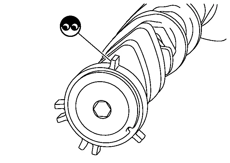
Provide 12 V DC between exhaust valve timing control solenoid valve terminals 1 and 2, and then interrupt it. Check that the plunger moves as shown in the figure.

CAUTION:
Do not apply 12 V DC continuously for 5 seconds or more. Doing so may result in damage to the coil in exhaust valve timing control solenoid valve.
 NOTE:
NOTE: Always replace O-ring when exhaust valve timing control solenoid valve is removed.
Is the inspection result normal?
YES>>
INSPECTION END
NO>>
Replace malfunctioning exhaust valve timing control solenoid valve. Refer to Exploded View.
P0030 A/f Sensor 1 Heater Nissan Pathfinder 5th Gen
DTC Description
DTC DETECTION LOGIC
 NOTE:
NOTE:
When DTC P0036 is detected with DTC P0030 again after the inspection procedure is performed during previous diagnosis and it is judged to be normal, replace the harness between the air fuel ratio (A/F) sensor 1 and the IPDM E/R.
| DTC |
CONSULT screen terms (Trouble diagnosis content) |
DTC detection condition | ||
| P0030 | 00 |
HO2S1 HTR B1 (HO2S heater control circuit bank 1 sensor 1) |
Diagnosis condition | Engine running at idle |
| Signal (terminal) | A/F sensor 1 heater (bank 1) signal | |||
| Threshold |
Deterioration in A/F sensor 1 heater performance. (Voltage signal transmitted from A/F sensor 1 heater to ECM is higher/lower than voltage in the normal range.) |
|||
| Diagnosis delay time | — | |||
POSSIBLE CAUSE
-
Harness or connectors [A/F sensor 1 heater (bank 1) circuit is open or shorted.]
-
A/F sensor 1 heater (bank 1)
-
Short circuit of harness between the air fuel ratio (A/F) sensor 1 and heated oxygen sensor 2.
FAIL-SAFE
Not applicable
DTC Confirmation Procedure
CHECK DTC PRIORITY
When DTC P0030 is detected with DTC P0036, first perform to check the harness for short circuit between the heated oxygen sensor 2 and the air fuel ratio (A/F) sensor 1.
Is applicable DTC detected?
YES>>Perform to check the harness for short circuit between the heated oxygen sensor 2 and the air fuel ratio (A/F) sensor 1.
NO>>GO TO 2.
PRECONDITIONING
If DTC Confirmation Procedure has been previously conducted, always perform the following procedure before conducting the next test.
-
Ignition switch OFF and wait at least 10 seconds.
-
Ignition switch ON.
-
Ignition switch OFF and wait at least 10 seconds.
TESTING CONDITION:
Before performing the following procedure, confirm that battery voltage is between 10.5 V and 16 V at idle.
>>
GO TO 3.
PERFORM DTC CONFIRMATION PROCEDURE
-
Start engine and let it idle for at least 10 seconds.
-
Check 1st trip DTC.
Is DTC P0030 detected?
YES>>Proceed to Diagnosis Procedure.
NO-1>>Proceed to Diagnosis Procedure.
NO-2>>Confirmation after repair: INSPECTION END
Diagnosis Procedure
CHECK AIR FUEL RATIO (A/F) SENSOR 1 CONNECTOR FOR CONNECTION-1
Push the connector of air fuel ratio (A/F) sensor 1 and check it for connection.
Is the connector connected securely?
YES>>GO TO 2.
NO>>After connecting connector securely perform DTC confirmation procedure again. Refer to DTC Confirmation Procedure.
CHECK AIR FUEL RATIO (A/F) SENSOR 1 CONNECTOR INSIDE
Disconnect the air fuel ratio (A/F) sensor 1 connector and check inside the connector for water or foreign material.
Is inspection result normal?
YES>>GO TO 3.
NO>>Replace A/F sensor 1. Refer to Exploded View.
CHECK AIR FUEL RATIO (A/F) SENSOR 1 CONNECTOR FOR CONNECTION-2
Reconnect securely the connector of air fuel ratio (A/F) sensor 1 and check it for connection.
Is the connector connected securely?
YES>>GO TO 4.
NO>>Repair the harness connector and replace the air fuel ratio (A/F) sensor 1. Refer to Exploded View.
CHECK A/F SENSOR 1 POWER SUPPLY
-
Ignition switch OFF.
-
Disconnect A/F sensor 1 harness connector.
-
Ignition switch ON.
-
Check the voltage between A/F sensor 1 harness connector and ground.
+ − Voltage A/F sensor 1 Bank Connector Terminal 1 F72 1 Ground Battery voltage
Is the inspection result normal?
YES>>GO TO 7.
NO>>GO TO 5.
CHECK IPDM E/R POWER SUPPLY AND GROUND CIRCUIT
Check IPDM E/R power supply and ground circuit. Refer to Diagnosis Procedure.
Is the inspection result normal?
YES>>GO TO 6.
NO>>Repair or replace malfunctioning part.
CHECK A/F SENSOR 1 POWER SUPPLY CIRCUIT
-
Ignition switch OFF.
-
Disconnect IPDM E/R harness connector.
-
Check the continuity between IPDM E/R harness connector and A/F sensor 1 harness connector.
IPDM E/R A/F sensor 1 Continuity Connector Terminal Connector Terminal F24 75 F72 1 Existed -
Also check harness for short to ground.
Is the inspection result normal?
YES>>Perform the trouble diagnosis for power supply circuit.
NO>>Repair or replace error-detected parts.
CHECK A/F SENSOR 1 HEATER OUTPUT SIGNAL CIRCUIT
-
Ignition switch OFF.
-
Disconnect ECM harness connector.
-
Check the continuity between A/F sensor 1 harness connector and ECM harness connector.
A/F sensor 1 ECM Continuity Bank Connector Terminal Connector Terminal 1 F72 2 F79 91 Existed -
Also check harness for short to power and short to ground.
Is the inspection result normal?
YES>>GO TO 8.
NO>>Repair or replace error-detected parts.
CHECK A/F SENSOR 1 HEATER
Check A/F sensor 1 heater. Refer to Component Inspection (A/F Sensor 1 Heater).
Is the inspection result normal?
YES>>Check intermittent incident. Refer to Intermittent Incident.
NO>>Replace malfunctioning A/F sensor 1. Refer to Exploded View.
Component Inspection (A/F Sensor 1 Heater)
CHECK A/F SENSOR 1
-
Ignition switch OFF.
-
Disconnect A/F sensor 1 harness connector.
-
Check resistance between A/F sensor 1 terminals as follows.
A/F sensor 1 Condition
Resistance Terminal 1 2 Temperature 25°C (77°F) 1.80 – 2.44 Ω 3 ∞Ω
(Continuity should not exist)4 2 3 4 3 4
Is the inspection result normal?
YES>>INSPECTION END
NO>>Replace malfunctioning A/F sensor 1. Refer to Exploded View.
P0078 Evt Control Solenoid Valve Nissan Pathfinder SUV
DTC Description
DTC DETECTION LOGIC
| DTC |
CONSULT screen terms (Trouble diagnosis content) |
DTC detection condition | ||
| P0078 | 00 |
EX V/T ACT/CIRC-B1 (Exhaust valve control solenoid circuit bank 1) |
Diagnosis condition | Engine running at idle |
| Signal (terminal) | Exhaust valve timing control solenoid valve (bank 1) signal | |||
| Threshold | An improper voltage is sent to the ECM through exhaust valve timing control solenoid valve | |||
| Diagnosis delay time | — | |||
POSSIBLE CAUSE
-
Harness or connectors (Exhaust valve timing control solenoid valve circuit is open or shorted.)
-
Exhaust valve timing control solenoid valve
FAIL-SAFE
| Fail safe mode | Nissan Pathfinder Vehicle behavior | |
|---|---|---|
| Device fix mode |
|
|
DTC Confirmation Procedure
PRECONDITIONING
If DTC Confirmation Procedure has been previously conducted, always perform the following procedure before conducting the next test.
-
Turn ignition switch OFF and wait at least 10 seconds.
-
Turn ignition switch ON.
-
Turn ignition switch OFF and wait at least 10 seconds.
>>
GO TO 2.
PERFORM DTC CONFIRMATION PROCEDURE
-
Start engine and let it idle for 5 seconds.
-
Check 1st trip DTC.
Is DTC P0078 detected?
YES>>Proceed to Diagnosis Procedure.
NO-1>>To check malfunction symptom before repair: Refer to Intermittent Incident.
NO-2>>Confirmation after repair: INSPECTION END
Diagnosis Procedure
CHECK EXHAUST VALVE TIMING CONTROL SOLENOID VALVE POWER SUPPLY
-
Turn ignition switch OFF.
-
Disconnect exhaust valve timing control solenoid valve harness connector.
-
Turn ignition switch ON.
-
Check the voltage between exhaust valve timing control solenoid valve harness connector and ground.
+ − Voltage Exhaust valve timing control solenoid valve Bank Connector Terminal 1 F77 1 Ground Battery voltage
Is the inspection result normal?
YES>>GO TO 3.
NO>>GO TO 2.
CHECK EXHAUST VALVE TIMING CONTROL SOLENOID VALVE POWER SUPPLY CIRCUIT
-
Turn ignition switch OFF.
-
Disconnect IPDM E/R harness connector.
-
Check the continuity between exhaust valve timing control solenoid valve harness connector and IPDM E/R harness connector.
Exhaust valve timing control solenoid valve IPDM E/R Continuity Bank Connector Terminal Connector Terminal 1 F77 1 F24 73 Existed -
Also check harness for short to ground.
Is the inspection result normal?
YES>>INSPECTION END
NO>>Repair or replace error-detected parts.
CHECK EXHAUST VALVE TIMING CONTROL SOLENOID VALVE OUTPUT SIGNAL CIRCUIT
-
Turn ignition switch OFF.
-
Disconnect ECM harness connector.
-
Check the continuity between exhaust valve timing control solenoid valve harness connector and ECM harness connector.
Exhaust valve timing control solenoid valve ECM Continuity Bank Connector Terminal Connector Terminal 1 F77 2 F79 157 Existed -
Also check harness for short to ground and short to power.
Is the inspection result normal?
YES>>GO TO 4.
NO>>Repair or replace error-detected parts.
CHECK EXHAUST VALVE TIMING CONTROL SOLENOID VALVE
Check exhaust valve timing control solenoid valve control solenoid valve. Refer to Component Inspection (Exhaust Valve Timing Control Solenoid Valve).
Is the inspection result normal?
YES>>INSPECTION END
NO>>Replace malfunctioning exhaust valve timing control solenoid valve. Refer to Exploded View.
Component Inspection (Exhaust Valve Timing Control Solenoid Valve)
CHECK EXHAUST VALVE TIMING CONTROL SOLENOID VALVE-I
-
Turn ignition switch OFF.
-
Disconnect exhaust valve timing control solenoid valve harness connector.
-
Check resistance between exhaust valve timing control solenoid valve terminals as per the following.
Exhaust valve timing control solenoid valve Condition
Resistance Terminal 1 2 Temperature [°C (°F)] 20 (68) 7.0 – 7.8 Ω 1 Ground ∞Ω
(Continuity should not exist)2
Is the inspection result normal?
YES>>GO TO 2.
NO>>Replace malfunctioning exhaust valve timing control solenoid valve. Refer to Exploded View.
CHECK EXHAUST VALVE TIMING CONTROL SOLENOID VALVE-II
-
Remove exhaust valve timing control solenoid valve. Refer to Exploded View.
-
Provide 12 V DC between exhaust valve timing control solenoid valve terminals 1 and 2, and then interrupt it. Check that the plunger moves as shown in the figure.
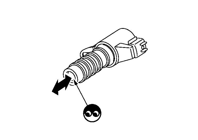
CAUTION:
Do not apply 12 V DC continuously for 5 seconds or more. Doing so may result in damage to the coil in exhaust valve timing control solenoid valve.
 NOTE:
NOTE:
Always replace O-ring when exhaust valve timing control solenoid valve is removed.
Is the inspection result normal?
YES>>INSPECTION END
NO>>Replace malfunctioning exhaust valve timing control solenoid valve. Refer to Exploded View.
P0087 Frp Control System ➤ Nissan Pathfinder 2026
DTC Description
DTC DETECTION LOGIC
 NOTE:
NOTE:
DTC P0087 may be displayed when running out of gas or air accumulation.
| DTC |
CONSULT screen terms (Trouble diagnosis content) |
DTC detection condition | |||
| P0087 | 00 |
LOW FUEL PRES (Fuel rail/system pressure - too low) |
A | Diagnosis condition | Engine running at idle |
| Signal (terminal) | Fuel rail pressure signal | ||||
| Threshold |
|
||||
| Diagnosis delay time | 5 seconds or more | ||||
POSSIBLE CAUSE
-
Fuel system
-
Leakage in fuel line
-
High pressure fuel pump
-
Low pressure fuel pump
-
Damage in lifter
-
Out of gas
-
Harness or connector
-
Fuel Pressure sensor
-
Fuel Injector stuck open
-
Clogged in fuel line
-
High Pressure fuel pump cam and lifter
FAIL-SAFE
| Fail safe mode | Nissan Pathfinder Vehicle behavior | |
|---|---|---|
| Traveling control mode | Accelerator angle variation control |
ECM controls the accelerator pedal depression speed to make it slower than actual speed. This causes a drop in accelerating performance and encourages the driver to repair malfunction. ECM does not control the accelerator pedal releasing speed.
|
| Device fix mode |
|
|
| Combustion control mode | Stratified charge combustion control at starting | No stratified charge combustion at starting (cold start). |
 NOTE:
NOTE: DTC Confirmation Procedure
CHECK DTC PRIORITY
If the following DTCs are detected together with P0087, prioritize the service for each DTC in the following order.
| Priority | DTC | Cause |
| 1 | P0090, P0091, P0092 | High pressure fuel pump, Harness, Fuse, Relay |
| P0190, P0191, P0192, P0193, P119C, P119D, P119E | Fuel pressure sensor, Harness | |
| P020x (x: Cyl No.), P0262, P0265, P0268, P0271, P0274, P0277 | Injector, Harness | |
| P025A, P025B, P025C, P025D | Low pressure fuel pump | |
| P0461, P0462 | Fuel gage, Harness | |
| P062B, P026D | ECM, Harness | |
| 2 | P119A, P119B | Fuel pressure sensor |
| 3 | P1197 | Fuel run out |
 NOTE:
NOTE:
Depending on the Nissan Pathfinder vehicle, there may be cases where the mentioned DTC codes are not detected.
Is applicable DTC detected?
YES>>
Perform the diagnosis of the applicable. Refer to DTC Index.
NO>>
GO TO 2.
CHECK FUEL LEAKAGE
-
Ignition switch ON.
-
Visually check the piping between low pressure fuel pump and fuel injectors for fuel leakage.
-
Start the engine.
-
Visually check the piping between low pressure fuel pump and fuel injectors for fuel leakage.
Is inspection result normal?
YES>>
GO TO 3.
NO>>
Repair or replace error-detected parts.
PRECONDITIONING
If DTC CONFIRMATION PROCEDURE has been previously conducted, always perform the following procedure before conducting the next test.
-
Ignition switch OFF and wait at least 10 seconds.
-
Ignition switch ON.
-
Ignition switch OFF and wait at least 10 seconds.
TESTING CONDITION:
-
Before performing the following procedure, confirm that battery voltage is 11 V or more at idle.
-
Before performing the following procedure, check that the fuel tank is 1/8 full of fuel.
>>
GO TO 4.
PERFORM DTC CONFIRMATION PROCEDURE-I
 With CONSULT
-
Ignition switch ON.
-
On CONSULT screen, select “ENGINE”>>“Data Monitor”>>“COOLAN TEMP/S”.
-
Check the following condition;
COOLAN TEMP/S −12 – 40°C (10.4 – 104°F)
 With GST
Follow the procedure “With CONSULT” above.
Is the condition satisfied?
YES>>
GO TO 5.
NO>>
-
Satisfy the condition.
-
Retry from step 1.
PERFORM DTC CONFIRMATION PROCEDURE-II
-
Start the engine and let it idle for 10 seconds.
-
Check 1st trip DTC.
Is DTC P0087 detected?
YES>>
Proceed to Diagnosis Procedure.
NO>>
GO TO 6.
PERFORM DTC CONFIRMATION PROCEDURE-III
 With CONSULT
-
On CONSULT screen, select “ENGINE”>>“Data Monitor”>>“COOLAN TEMP/S”.
-
Maintain the following condition for 10 seconds or more at idle.
COOLAN TEMP/S 70°C (158°F) or more -
Check 1st trip DTC.
 With GST
Follow the procedure “With CONSULT” above.
Is DTC P0087 detected?
YES>>
Proceed to Diagnosis Procedure.
NO-1>>
To check malfunction symptom before repair: Refer to Intermittent Incident.
NO-2>>
Confirmation after repair: INSPECTION END
Diagnosis Procedure
CHECK DTC PRIORITY
If the following DTCs are detected together with P0087, prioritize the service for each DTC in the following order.
| Priority | DTC | Cause |
| 1 | P0090, P0091, P0092 | High pressure fuel pump, Harness, Fuse, Relay |
| P0190, P0191, P0192, P0193, P119C, P119D, P119E | Fuel pressure sensor, Harness | |
| P020x (x: Cyl No.), P0262, P0265, P0268, P0271, P0274, P0277 | Injector, Harness | |
| P025A, P025B, P025C, P025D | Low pressure fuel pump | |
| P0461, P0462 | Fuel gage, Harness | |
| P062B, P026D | ECM, Harness | |
| 2 | P119A, P119B | Fuel pressure sensor |
| 3 | P1197 | Fuel run out |
 NOTE:
NOTE:
Depending on the Nissan Pathfinder vehicle, there may be cases where the mentioned DTC codes are not detected.
Is applicable DTC detected?
YES>>
Perform the diagnosis of the applicable. Refer to DTC Index.
NO>>
GO TO 2.
CHECK FUEL LEVEL
Check that the fuel level is enough.
Is there 1/8 or more fuel?
YES>>
GO TO 4.
NO>>
GO TO 3.
REFUEL THE Nissan Pathfinder Vehicle
-
Refuel to over 1/8 of full.
-
Start the engine and keep the engine speed at 3,000 rpm for 30 seconds.
 NOTE:
NOTE: For best results, warm up the engine until “COOLAN TEMP/S” on “DATA MONITOR” mode of “ENGINE” reaches at least 70°C (158°F).
-
Ignition switch OFF and wait at least 10 seconds.
-
Ignition switch ON.
-
Ignition switch OFF and wait at least 10 seconds.
-
Ignition switch ON.
-
Erase the DTC.
-
Start the engine and let it idle at least 60 seconds.
-
Perform DTC confirmation procedure again. Refer to DTC Description.
Is DTC P0087 detected?
YES>>
GO TO 4.
NO>>
INSPECTION END
AIR BLEED THE FUEL LINE
-
Start the engine, and let the engine run at idle at least for 10 minutes.
-
Perform DTC confirmation procedure of DTC P0087.
Is 1st trip DTC detected?
YES>>
GO TO 5.
NO>>
GO TO 18.
CHECK HIGH FUEL PRESSURE (FEED PRESSURE)
-
Perform fuel pressure release. Refer to Work Procedure.
-
Ignition switch ON and select “DATA MONITOR” mode of “ENGINE” using CONSULT.
-
Check the indication of “FUEL PRES SEN”.
Monitor item Indication FUEL PRES SEN Approx. 0.450 Mpa or more
Check high pressure fuel pump. Refer to Component Inspection (High Pressure Fuel Pump).
Is inspection result normal?
YES>>
GO TO 6.
NO>>
GO TO 10.
CHECK HIGH PRESSURE FUEL PUMP
Check high pressure fuel pump. Refer to Component Inspection (High Pressure Fuel Pump).
Is inspection result normal?
YES>>
GO TO 7.
NO>>
Repair or replace the error-detected parts.
CHECK FUEL RAIL PRESSURE SENSOR
Check fuel rail pressure sensor. Refer to Component Inspection (Fuel Rail Pressure Sensor).
Is inspection result normal?
YES>>
GO TO 8.
NO>>
Repair or replace the error-detected parts.
CHECK HIGH PRESSURE FUEL LEAKAGE
-
Start the engine.
-
Visually check that the high pressure fuel pump, fuel rail, and fuel piping have no fuel leakage.
Is inspection result normal?
YES>>
GO TO 9.
NO>>
Replace the error-detected parts.
CHECK HIGH PRESSURE FUEL PUMP LIFTER
Check high pressure fuel pump lifter. Refer to Removal and Installation.
Does the lifter top surface have scratches and/or dents?
YES>>
Replace the error-detected parts.
NO>>
GO TO 16.
CHECK LOW FUEL PRESSURE
Check low fuel pressure. Refer to Work Procedure.
Is inspection result normal?
YES>>
GO TO 11.
NO>>
GO TO 16.
CHECK FUEL RAIL PRESSURE SENSOR
Check fuel rail pressure sensor. Refer to Component Inspection (Fuel Rail Pressure Sensor).
Is inspection result normal?
YES>>
GO TO 12.
NO>>
Repair or replace the error-detected parts.
CHECK HIGH PRESSURE FUEL LEAKAGE
-
Start the engine.
-
Visually check that the high pressure fuel pump, fuel rail, and fuel piping have no fuel leakage.
Is inspection result normal?
YES>>
GO TO 13.
NO>>
Replace the error-detected parts.
CHECK HIGH PRESSURE FUEL PUMP LIFTER
Check high pressure fuel pump lifter. Refer to Removal and Installation.
Does the lifter top surface have scratches and/or dents?
YES>>
Replace the error-detected parts.
NO>>
GO TO 14.
REPLACE HIGH PRESSURE FUEL PUMP
Replace the high pressure fuel pump. Refer to Removal and Installation.
>>
GO TO 15.
PERFORM DTC CONFIRMATION PROCEDURE
-
Erase DTC.
-
Perform DTC confirmation procedure. Refer to DTC Confirmation Procedure.
Is the DTC P0087 detected again?
YES>>
Replace the fuel rail. Refer to Removal and Installation.
NO>>
INSPECTION END
CHECK LOW PRESSURE FUEL PUMP
Check low pressure fuel pump. Refer to Component Function Check.
Is inspection result normal?
YES>>
GO TO 17.
NO>>
Repair or replace the error-detected parts.
DETECT MALFUNCTIONING PART
Check fuel hoses and fuel tubes for clogging.
Is inspection result normal?
YES>>
GO TO 18.
NO>>
Repair or replace the error-detected parts.
CHECK FPCM
Check FPCM. Refer to Component Inspection (Fuel Pump Control Module).
Is inspection result normal?
YES>>
GO TO 19.
NO>>
Repair or replace the error-detected parts.
CHECK LOW PRESSURE FUEL LINE FOR INTERNAL LEAKAGE
-
Start the engine.
-
Visually check that the low pressure fuel pump, fuel rail, and fuel piping have no fuel leakage.
Is inspection result normal?
YES>>
INSPECTION END
NO>>
Replace the error-detected parts.
Component Inspection (High Pressure Fuel Pump)
CHECK HIGH PRESSURE FUEL PUMP-I
-
Ignition switch OFF.
-
Disconnect high pressure fuel pump harness connector.
-
Check the resistance between high pressure fuel pump terminals.
High pressure fuel pump Condition Resistance + − Terminal 1 2 Temperature °C (°F) 20 (68) 0.45 – 0.55 Ω
Is the inspection result normal?
YES>>
GO TO 2.
NO>>
Replace high pressure fuel pump. Refer to Removal and Installation.
CHECK HIGH PRESSURE FUEL PUMP-II
 With CONSULT
-
Reconnect high pressure fuel pump harness connector.
-
Start engine.
-
On CONSULT screen, select “ENGINE”>>“Data Monitor”.
-
Check that the “FUEL PRES SEN V” indication.
Monitor Item Condition Values/Status FUEL PRES SEN V Engine speed: Idle 1.120 – 1.310 V Engine speed: Revving engine from idle to 4,000 rpm quickly 1.120 – 2.900 V
 Without CONSULT
-
Reconnect high pressure fuel pump harness connector.
-
Start engine.
-
Check fuel rail pressure sensor signal voltage.
| ECM | Condition | Voltage | ||
|---|---|---|---|---|
| Connector | + | − | ||
| Terminal | ||||
| F78 | 47 | 85 | Engine speed: Idle | 1.12 – 1.31 V |
| Engine speed: Revving engine from idle to 4,000 rpm quickly | 1.12 – 2.90 V | |||
Is the inspection result normal?
YES>>
INSPECTION END
NO>>
Replace high pressure fuel pump. Refer to Removal and Installation.
P00d2 Ho2s2 Heater Nissan Pathfinder Fifth generation
DTC Description
DTC DETECTION LOGIC
| DTC |
CONSULT screen terms (Trouble diagnosis content) |
DTC detection condition | ||
| P00D2 | 00 |
Heated O2 sensor heater B1 sensor 2 (HO2S heater controlcircuit range/performance bank 1 sensor 2) |
Diagnosis condition | — |
| Signal (terminal) | Heated oxygen sensor 2 heater signal | |||
| Threshold | Deterioration in heated oxygen sensor 2 heater (bank 1) performance. (Voltage signal transmitted from heated oxygen sensor 2 heater (bank 1) to ECM is higher /lower than voltage in the normal range.) | |||
| Diagnosis delay time | — | |||
POSSIBLE CAUSE
-
Harness or connectors
[The heated oxygen sensor 2 heater (bank 1) circuit is open or shorted.]
-
Heated oxygen sensor 2 heater (bank 1)
FAIL-SAFE
Not applicable
DTC Confirmation Procedure
PRECONDITIONING
-
Turn ignition switch OFF and wait at least 10 seconds.
-
Turn ignition switch ON.
-
Turn ignition switch OFF and wait at least 10 seconds.
TESTING CONDITION:
Before performing the following procedure, confirm that battery voltage is 11 V or more at idle.
>>
GO TO 2.
PERFORM DTC CONFIRMATION PROCEDURE
-
Start engine and warm it up to the normal operating temperature.
-
Turn ignition switch OFF and wait at least 10 seconds.
-
Turn ignition switch ON.
-
Turn ignition switch OFF and wait at least 10 seconds.
-
Start engine and keep the engine speed between 3,500 and 4,000 rpm for at least 1 minute under no load.
-
Let engine idle for 1 minute.
-
Check 1st trip DTC.
Is 1st trip DTC detected?
YES>>Proceed to Diagnosis Procedure.
NO-1>>To check malfunction symptom before repair: Refer to Intermittent Incident.
NO-2>>Confirmation after repair: INSPECTION END
Diagnosis Procedure
CHECK HEATED OXYGEN SENSOR 2 (HO2S2) POWER SUPPLY CIRCUIT
-
Disconnect heated oxygen sensor 2 (HO2S2) harness connector.
-
Turn ignition switch ON.
-
Check the voltage between HO2S2 harness connector and ground.
DTC HO2S2 Ground Voltage Bank Connector Terminal P00D2 1 F71 1 Ground Battery voltage
Is the inspection result normal?
YES>>GO TO 3.
NO>>GO TO 2.
DETECT MALFUNCTIONING PART
Check the following.
-
15A fuse (No. 82)
-
Harness for open or short between heated oxygen sensor 2 and fuse
-
Loose or poor connection for each connector and harness
>>
Repair open circuit, short to ground or short to power in harness or connectors.
CHECK HO2S2 OUTPUT SIGNAL CIRCUIT FOR OPEN AND SHORT
-
Turn ignition switch OFF.
-
Disconnect ECM harness connector.
-
Check the continuity between HO2S2 harness connector and ECM harness connector.
DTC HO2S2 ECM Continuity Bank Connector Terminal Connector Terminal P00D2 1 F71 2 F78 6 Existed -
Also check harness for short to ground and short to power.
Is the inspection result normal?
YES>>GO TO 4.
NO>>Repair open circuit, short to ground or short to power in harness or connectors.
CHECK HO2S2 HEATER
Refer to Component Inspection.
Is the inspection result normal?
YES>>GO TO 6.
NO>>GO TO 5.
REPLACE HEATED OXYGEN SENSOR 2
Replace malfunctioning heated oxygen sensor 2. Refer to Removal and Installation.
CAUTION:
-
Discard any heated oxygen sensor which has been dropped from a height of more than 0.5 m (19.7 in) onto a hard surface such as a concrete floor; use a new one.
-
Before installing new oxygen sensor, clean exhaust system threads using Oxygen Sensor Thread Cleaner [commercial service tool (NI-43897-18 or NI-43897-12)] and approved anti-seize lubricant (commercial service tool).
>>
INSPECTION END
CHECK INTERMITTENT INCIDENT
Refer to Intermittent Incident.
>>
INSPECTION END
Component Inspection
HEATED OXYGEN SENSOR 2 HEATER
-
Check resistance between HO2S2 terminals as follows.
Terminal No. Resistance 1 and 2 5.4 – 7.3 Ω at 25°C (77°F) 2 and 3, 4 ∞Ω
(Continuity should not exist)3 and 4 -
If NG, replace heated oxygen sensor 2.
CAUTION:
-
Discard any heated oxygen sensor which has been dropped from a height of more than 0.5 m (19.7 in) onto a hard surface such as a concrete floor; use a new one.
-
Before installing new oxygen sensor, clean exhaust system threads using Oxygen Sensor Thread Cleaner tool NI-43897-18 or NI-43897-12 and approved anti-seize lubricant.
P00fe Evap Control System Nissan Pathfinder 5th Gen
DTC Description
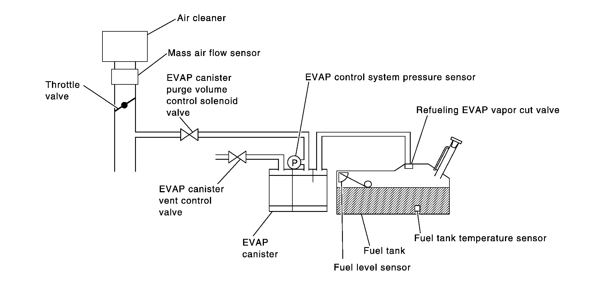
This diagnosis detects clogs in the EVAP line between fuel tank and EVAP canister purge volume control solenoid valve.
ECM controls EVAP control system as below. ECM monitors EVAP line pressure change to diagnose if there is no clogging between EVAP canister and fuel tank.
-
ECM closes EVAP canister vent control valve while the engine is running.
-
ECM controls EVAP canister purge volume control solenoid valve. (Fuel vapor in EVAP line is absorbed by intake manifold pressure)
-
ECM monitors EVAP line pressure change using EVAP control system pressure sensor. (When there is clogging in EVAP line, the path to the space of fuel tank is partially blocked. As a result, the pressure in EVAP line drops faster.)
DTC DETECTION LOGIC
| DTC |
CONSULT screen terms (Trouble diagnosis content) |
DTC detection condition | ||
| P00FE | 00 |
EVAP system vapor line (EVAP system tank vapor line restricted/blocked) |
Diagnosis condition | — |
| Signal (terminal) | — | |||
| Threshold | When EVAP canister vent control valve is closed while EVAP canister purge volume control solenoid valve is activated, the pressure of EVAP control system drops extraordinary. | |||
| Diagnosis delay time | — | |||
POSSIBLE CAUSE
-
Fuel tank vent line (bent, clogs, etc.)
-
EVAP canister
FAIL-SAFE
Not applicable
DTC CONFIRMATION PROCEDURE
PRECONDITIONING
If DTC Confirmation Procedure has been previously conducted, always perform the following before conducting the next test.
-
Turn ignition switch OFF and wait at least 10 seconds.
-
Turn ignition switch ON.
-
Turn ignition switch OFF and wait at least 10 seconds.
>>
GO TO 2.
PERFORM DTC CONFIRMATION PROCEDURE
-
Drive the Nissan Pathfinder vehicle under the following conditions for at least 5 minutes in total.
Engine coolant temperature 70°C (158°F) or more Nissan Pathfinder Vehicle speed 60 – 100 km/h (37 – 62 MPH)  NOTE:
NOTE:
Keep the accelerator pedal as possible during cruising.
-
Check DTC.
Is 1st trip DTC detected?
YES>>Proceed to Diagnosis Procedure.
NO-1>>To check malfunction symptom before repair: Refer to Intermittent Incident .
NO-2>>Confirmation after repair: INSPECTION END
Diagnosis Procedure
CHECK EVAP CONTROL SYSTEM FOR CLOGGING
 With CONSULT
-
Turn ignition switch OFF.
-
Disconnect EVAP purge hose
 from EVAP canister purge volume control valve.
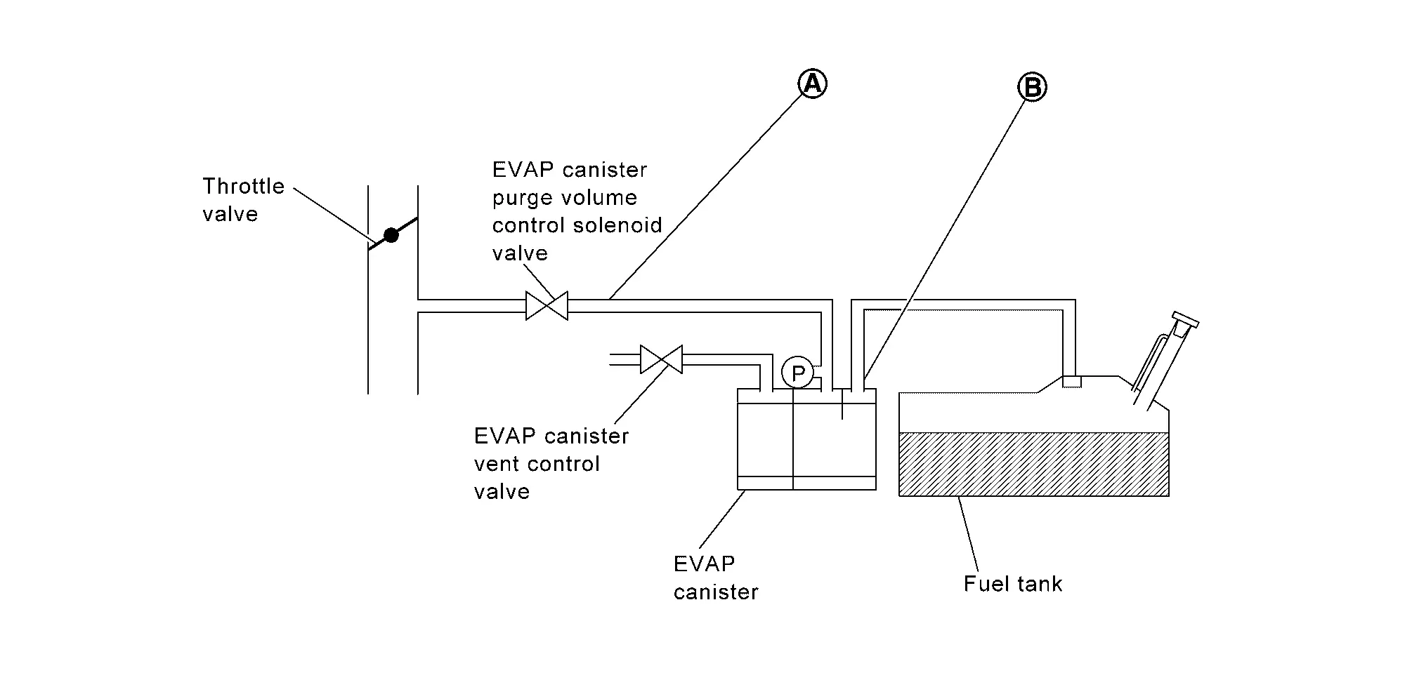
-
Disconnect fuel tank vent hose
 from EVAP canister.
 -
Turn ignition switch ON (engine stopped).
-
On CONSULT screen, select “ENGINE” >> “Work support” >> “EVAP SYSTEM CLOSE”.
-
Apply positive pressure (not vacuum) to the hose end
 using Vacuum/Pressure Hand Pump according to CONSULT screen instructions.
 -
Check that the applied pressure does not increase and that pressure is not held.
Is the inspection result normal?
YES>>Check fuel tank vent line for clogs, vent and installation condition.
NO>>Replace EVAP canister. Refer to Removal and Installation.
P0101 Maf Sensor Nissan Pathfinder 2026
DTC Description
DTC DETECTION LOGIC
| DTC |
CONSULT screen terms (Trouble diagnosis content) |
DTC detection condition | ||
| P0101 | 00 |
MAF SEN/CIRCUIT-B1 (Mass or volume air flow “A” circuit range/performance) |
Diagnosis condition | — |
| Signal (terminal) | Mass air flow sensor signal | |||
| Threshold |
|
|||
| Diagnosis delay time | — | |||
POSSIBLE CAUSE
-
Harness or connectors (The mass air flow sensor circuit is open or shorted.)
-
Mass air flow sensor
-
EVAP control system pressure sensor
-
Intake air leaks
-
Intake air temperature sensor
-
Electric throttle control actuator
-
PCV hose air leak
-
Purge hose air leak
FAIL-SAFE
| Fail safe mode | Nissan Pathfinder Vehicle behavior | |
|---|---|---|
| Traveling control mode | Accelerator angle variation control |
ECM controls the accelerator pedal depression speed to make it slower than actual speed. This causes a drop in accelerating performance and encourages the driver to repair malfunction. ECM does not control the accelerator pedal releasing speed.
|
| Engine output control |
ECM reduces the engine output, according to the rise in engine speed. This reduces the Nissan Pathfinder vehicle speed to encourage the driver to repair malfunction.
This value is a reference value converted from engine power to Nissan Pathfinder vehicle speed. Actual power limitation value differs due to the malfunctioning part and driving condition.
|
|
| Device fix mode |
|
|
| Combustion control mode | Stratified charge combustion control at starting | No stratified charge combustion at starting (cold start). |
| Idle speed control | Stops feedback control of idle speed and controls with specified speed. | |
| Recovery speed control at decelerating | Stops recovery speed control by the fuel cut at decelerating and controls with specified speed. | |
| Idle neutral control | Stops idle neutral control. | |
| Ignition timing correction control | Partially controls ignition timing control. | |
| Retardation control | Controls ignition timing delay control in the intermediate water temperature range. | |
 NOTE:
NOTE:  NOTE:
NOTE: DTC Confirmation Procedure
CHECK DTC PRIORITY
If DTC P0101 is displayed with other DTC, first perform the confirmation procedure (trouble diagnosis) for other DTC.
Is applicable DTC detected?
YES>>
Perform diagnosis of applicable. Refer to DTC Index.
NO>>
GO TO 2.
PRECONDITIONING
-
Turn ignition switch OFF and wait at least 10 seconds.
-
Turn ignition switch ON.
-
Turn ignition switch OFF and wait at least 10 seconds.
If engine will not start or stops soon, wait at least 10 seconds with engine stopped (Ignition switch ON) instead of running engine at idle speed.
>>
GO TO 3.
PERFORM DTC CONFIRMATION PROCEDURE
-
Start engine and warm it up to normal operating temperature.
-
Drive the Nissan Pathfinder vehicle for at least 5 seconds under the following conditions:
CAUTION:
Always drive at a safe speed.
Selector lever Suitable position Nissan Pathfinder Vehicle speed 40 km/h (25 MPH) or more  NOTE:
NOTE: -
The gear must be fixed while driving the Nissan Pathfinder vehicle.
-
Keep the accelerator pedal as steady as possible during cruising.
-
-
Check 1st trip DTC.
Is DTC P0101 detected?
YES>>
Proceed to Diagnosis Procedure.
NO>>
To check malfunction symptom before repair: Refer to Intermittent Incident.
NO>>
Confirmation after repair: INSPECTION END
Diagnosis Procedure
CHECK DTC PRIORITY
If DTC P0101 is displayed with other DTC, first perform the confirmation procedure (trouble diagnosis) for other DTC.
Is applicable DTC detected?
YES>>
Perform diagnosis of applicable. Refer to DTC Index.
NO>>
GO TO 2.
CHECK HARNESS CONNECTOR
-
Disconnect mass air flow sensor harness connector and ECM harness connector.
-
Connect mass air flow sensor harness connector and ECM harness connector.
-
Perform DTC confirmation procedure. Refer to DTC Confirmation Procedure.
Is DTC detected?
YES>>
GO TO 3.
NO>>
INSPECTION END
CHECK INTAKE SYSTEM
Check the following items to see the installation condition and the connection condition of the joint.
-
Air duct
-
Vacuum hoses
-
Intake air passage between air duct and intake manifold
Is the inspection result normal?
YES>>
GO TO 4.
NO>>
Reconnect or replace error-detected parts.
CHECK MASS AIR FLOW SENSOR POWER SUPPLY
-
Disconnect mass air flow sensor harness connector.
-
Turn ignition switch ON.
-
Check the voltage between mass air flow sensor harness connector and ground.
+ – Voltage
(Approx.)Mass air flow sensor Connector Terminal E64 1 Ground 5 V
Is the inspection result normal?
YES>>
GO TO 6.
NO>>
GO TO 5.
CHECK MASS AIR FLOW SENSOR POWER SUPPLY CIRCUIT
-
Turn ignition switch OFF.
-
Disconnect ECM harness connector.
-
Check the continuity between mass air flow sensor harness connector and ECM harness connector.
Mass air flow sensor ECM Continuity Connector Terminal Connector Terminal E64 1 F78 41 Existed -
Also check harness for short to power and short to ground.
Is the inspection result normal?
YES>>
Perform the trouble diagnosis for ECM power supply circuit. Refer to Diagnosis Procedure.
NO>>
Repair or replace error-detected parts.
CHECK MASS AIR FLOW SENSOR GROUND CIRCUIT
-
Turn ignition switch OFF.
-
Disconnect ECM harness connector.
-
Check the continuity between mass air flow sensor harness connector and ECM harness connector.
Mass air flow sensor ECM Continuity Connector Terminal Connector Terminal E64 3 F78 30 Existed -
Also check harness for short to power.
Is the inspection result normal?
YES>>
GO TO 7.
NO>>
Repair or replace error-detected parts.
CHECK ECM GROUND CIRCUIT
-
Check the continuity between ECM harness connector and ground.
ECM — Continuity Connector Terminal F78 3 Ground Existed F79 87 E32 199 201 204 -
Also check harness for short to power.
Is the inspection result normal?
YES>>
GO TO 8.
NO>>
Repair or replace error-detected parts.
CHECK MASS AIR FLOW SENSOR INPUT SIGNAL CIRCUIT
-
Check the continuity between mass air flow sensor harness connector and ECM harness connector.
Mass air flow sensor ECM Continuity Connector Terminal Connector Terminal E64 2 F78 33 Existed -
Also check harness for short to power and short to ground.
Is the inspection result normal?
YES>>
GO TO 9.
NO>>
Repair or replace error-detected parts.
CHECK INTAKE AIR TEMPERATURE SENSOR
Check intake air temperature sensor. Refer to Component Inspection (Intake Air Temperature Sensor).
Is the inspection result normal?
YES>>
GO TO 10.
NO>>
Replace mass air flow sensor (with intake air temperature sensor). Refer to Exploded View.
CHECK PCV VALVE
Check the PCV valve. Refer to Inspection.
Is the inspection result normal?
YES>>
GO TO 11.
NO>>
Replace PCV valve.
PERFORM IDLE AIR VOLUME LEARNING
Perform the idle air volume learning. Refer to Work Procedure.
>>
GO TO 12.
CHECK EVAP CONTROL SYSTEM PRESSURE SENSOR
Refer to Component Inspection.
Is the inspection result normal?
YES>>
GO TO 13.
NO>>
Replace EVAP control system pressure sensor. Refer to Removal and Installation.
PERFORM EVAP LEAK CHECK
Perform EVAP leak check. Refer to Inspection.
>>
GO TO 14.
CHECK MASS AIR FLOW SENSOR
Check mass air flow sensor. Refer to Component Inspection (Mass Air Flow Sensor).
Is the inspection result normal?
YES>>
INSPECTION END
NO>>
Replace mass air flow sensor. Refer to Exploded View.
P0107 Barometric Pressure Sensor Nissan Pathfinder Fifth generation
DTC Description
DTC DETECTION LOGIC
| DTC |
CONSULT screen terms (Trouble diagnosis content) |
DTC detection condition | ||
| P0107 | 00 |
ABSL PRES SEN/CIRC (Barometric pressure sensor circuit low input) |
Diagnosis condition | — |
| Signal (terminal) | — | |||
| Threshold | An excessively low voltage from the barometric pressure sensor (built-into ECM) is sent to ECM. | |||
| Diagnosis delay time | — | |||
POSSIBLE CAUSE
Barometric pressure sensor (built-into ECM)
FAIL-SAFE
| Fail safe mode | Nissan Pathfinder Vehicle behavior | |
|---|---|---|
| Traveling control mode | Accelerator angle variation control |
ECM controls the accelerator pedal depression speed to make it slower than actual speed. This causes a drop in accelerating performance and encourages the driver to repair malfunction.
ECM does not control the accelerator pedal releasing speed. |
| Engine output control |
ECM reduces the engine output, according to the rise in engine speed. This reduces the Nissan Pathfinder vehicle speed to encourage the driver to repair malfunction.
This value is a reference value converted from engine power to Nissan Pathfinder vehicle speed. Actual power limitation value differs due to the malfunctioning part and driving condition. |
|
| Device fix mode |
|
|
 NOTE:
NOTE:
 NOTE:
NOTE:
DTC CONFIRMATION PROCEDURE
PRECONDITIONING
If DTC Confirmation Procedure has been previously conducted, always perform the following procedure before conducting the next test.
-
Turn ignition switch OFF and wait at least 10 seconds.
-
Turn ignition switch ON.
-
Turn ignition switch OFF and wait at least 10 seconds.
>>
GO TO 2.
PERFORM DTC CONFIRMATION PROCEDURE
-
Start engine and let it idle for 5 seconds.
-
Check 1st trip DTC.
Is 1st trip DTC detected?
YES>>Proceed to Diagnosis Procedure.
NO-1>>To check malfunction symptom before repair: Refer to Intermittent Incident.
NO-2>>Confirmation after repair: INSPECTION END
Diagnosis Procedure
DTC CONFIRMATION
-
Turn ignition switch ON.
-
Erase DTC.
-
Perform DTC confirmation procedure. Refer to DTC Description.
-
Check the DTC.
Is the DTC displayed again?
YES>>Replace ECM. Refer to Removal and Installation.
NO>>INSPECTION END
P0111 Iat Sensor Nissan Pathfinder 5th Gen
DTC Description
DTC DETECTION LOGIC
| DTC |
CONSULT screen terms (Trouble diagnosis content) |
DTC detection condition | ||
| P0111 | 00 |
IAT SENSOR 1 B1 (Intake air temperature sensor 1 circuit range/performance bank 1) |
Diagnosis condition | Engine cold start |
| Signal (terminal) | Intake air temperature sensor signal | |||
| Threshold | The comparison result of signals transmitted to ECM from each temperature sensor (IAT sensor, ECT sensor, FTT sensor, and EOT sensor) shows that the voltage signal of the IAT sensor is higher/lower than that of other temperature sensors. | |||
| Diagnosis delay time | — | |||
POSSIBLE CAUSE
-
Harness or connectors (High or low resistance in the IAT sensor circuit)
-
Mass air flow sensor (IAT sensor)
FAIL-SAFE
Not applicable
DTC Confirmation Procedure
INSPECTION START
Is it necessary to erase permanent DTC?
YES>>GO TO 3.
NO>>GO TO 2.
PERFORM COMPONENT FUNCTION CHECK
 NOTE:
NOTE:
Use the component function check to check the overall function of the IAT sensor circuit. During this check, a 1st trip DTC might not be confirmed.
-
Turn ignition switch OFF.
-
Disconnect mass air flow sensor harness connector.
-
Check resistance between mass air flow sensor terminals as follows.
Mass air flow sensor Condition Resistance Terminal 3 4 Temperature [°C (°F)] 25 (77) 1.80 – 2.20 kΩ
Is the inspection result normal?
YES-1>>To check malfunction symptom before repair: Refer to Intermittent Incident.
YES-2>>Confirmation after repair: INSPECTION END
NO>>Proceed to Diagnosis Procedure.
PRECONDITIONING
If DTC CONFIRMATION PROCEDURE has been previously conducted, always perform the following procedure before conducting the next test.
-
Turn ignition switch OFF and wait at least 10 seconds.
-
Turn ignition switch ON.
-
Turn ignition switch OFF and wait at least 10 seconds.
TESTING CONDITION:
-
Before performing the following procedure, do not add fuel.
-
Before performing the following procedure, check that fuel level is between 1/4 and 4/4.
-
Before performing the following procedure, confirm that battery voltage is 11 V or more at idle.
>>
GO TO 4.
PERFORM DTC CONFIRMATION PROCEDURE
-
Move the Nissan Pathfinder vehicle to a cool place.
 NOTE:
NOTE:
Cool the vehicle in an environment of ambient air temperature between −10°C (14°F) and 35°C (95°F).
-
Turn ignition switch OFF and leave the Nissan Pathfinder vehicle for 12 hours.
CAUTION:
Never turn ignition switch ON during this procedure.
 NOTE:
NOTE:
The Nissan Pathfinder vehicle must be cooled with the hood open.
-
Start engine and let it idle for 5 minutes or more.
CAUTION:
Never turn ignition switch OFF during idling.
-
Check 1st trip DTC.
Is DTC P0111 detected?
YES>>Proceed to Diagnosis Procedure.
NO-1>>To check malfunction symptom before repair: Refer to Intermittent Incident.
NO-2>>Confirmation after repair: INSPECTION END
Diagnosis Procedure
CHECK INTAKE AIR TEMPERATURE SENSOR
Check intake air temperature sensor. Refer to Component Inspection.
Is the inspection result normal?
YES>>INSPECTION END
NO>>Replace mass air flow sensor (with intake air temperature sensor). Refer to Exploded View.
Component Inspection
CHECK INTAKE AIR TEMPERATURE SENSOR
 With CONSULT
-
Turn ignition switch OFF.
-
Disconnect mass air flow (MAF) sensor (intake air temperature sensor is built-into) harness connector and reconnect it.
-
Turn ignition switch ON.
-
On CONSULT screen, select “ENGINE”>>“Data Monitor”>>“INT/A TEMP SEN”.
-
Check that the indicated value of “INT/A TEMP SEN” is almost the same as intake air temperature.
Is the inspection result normal?
YES>>INSPECTION END
NO>>Replace mass air flow sensor (with intake air temperature sensor). Refer to Exploded View.

Nissan Pathfinder (R53) 2022-2026 Service Manual
Dtc/circuit Diagnosis (P0011 Intake Valve Timing Control ... P0111 Iat Sensor)
- P0011 Intake Valve Timing Control
- P0014 Evt Control
- P0030 A/f Sensor 1 Heater
- P0078 Evt Control Solenoid Valve
- P0087 Frp Control System ➤
- P00d2 Ho2s2 Heater
- P00fe Evap Control System
- P0101 Maf Sensor
- P0107 Barometric Pressure Sensor
- P0111 Iat Sensor
Contact Us
Nissan Pathfinder Info Center
Email: info@nipathfinder.com
Phone: +1 (800) 123-4567
Address: 123 Pathfinder Blvd, Nashville, TN 37214, USA
Working Hours: Mon–Fri, 9:00 AM – 5:00 PM (EST)
