Nissan Pathfinder: Dtc/circuit Diagnosis (P2118 Throttle Control Motor ... P34ac Electric Intake Valve Timing Control Actuator)
- P2118 Throttle Control Motor
- P2119 Electric Throttle Control Actuator
- P2122 App Sensor
- P2138 App Sensor
- P219a Air Fuel Ratio
- P2297 Air Fuel Ratio Sensor 1
- P25df Electric Intake Valve Timing Control Motor
- P2610 Ecm Internal Timer
- P2b96 Injection Pulse
- P34ac Electric Intake Valve Timing Control Actuator
P2118 Throttle Control Motor Nissan Pathfinder SUV
DTC Description
DTC DETECTION LOGIC
| DTC |
CONSULT screen terms (Trouble diagnosis content) |
DTC detection condition | ||
| P2118 | 00 |
ETC MOT-B1 (Throttle control motor circuit short) |
Diagnosis condition | Engine running at idle |
| Signal (terminal) | Throttle control motor signal | |||
| Threshold | ECM detects short in both circuits between ECM and throttle control motor | |||
| Diagnosis delay time | — | |||
POSSIBLE CAUSE
-
Harness or connectors (Throttle control motor circuit is shorted.)
-
Electric throttle control actuator
FAIL-SAFE
| Fail safe mode | Nissan Pathfinder Vehicle behavior | |
|---|---|---|
| Device fix mode |
|
|
| Electric throttle control cancel mode | ECM stops the electric throttle control actuator control, throttle valve is maintained at a fixed opening (approx. 5 degrees) by the return spring. | |
DTC Confirmation Procedure
PRECONDITIONING
If DTC Confirmation Procedure has been previously conducted, always perform the following procedure before conducting the next test.
-
Turn ignition switch OFF and wait at least 10 seconds.
-
Turn ignition switch ON.
-
Turn ignition switch OFF and wait at least 10 seconds.
>>
GO TO 2.
PERFORM DTC CONFIRMATION PROCEDURE
-
Turn ignition switch ON and wait at least 2 seconds.
-
Start engine and let it idle for 5 seconds.
-
Check DTC.
Is DTC P2118 detected?
YES>>Proceed to Diagnosis Procedure.
NO-1>>To check malfunction symptom before repair: Refer to Intermittent Incident.
NO-2>>Confirmation after repair: INSPECTION END
Diagnosis Procedure
CHECK THROTTLE CONTROL MOTOR OUTPUT SIGNAL CIRCUIT
-
Turn ignition switch OFF.
-
Disconnect electric throttle control actuator harness connector.
-
Disconnect ECM harness connector.
-
Check the continuity between electric throttle control actuator harness connector and ECM harness connector.
Electric throttle control actuator ECM Continuity Connector Terminal Connector Terminal F50 2 F79 148 Existed 147 Not existed 1 148 Not existed 147 Existed -
Also check harness for short to power and short to ground.
Is the inspection result normal?
YES>>GO TO 2.
NO>>Repair or replace error-detected parts.
CHECK THROTTLE CONTROL MOTOR
Check the throttle control motor. Refer to Component Inspection.
Is the inspection result normal?
YES>>INSPECTION END
NO>>Replace electric throttle control actuator. Refer to Exploded View.
Component Inspection
CHECK THROTTLE CONTROL MOTOR
-
Turn ignition switch OFF.
-
Disconnect electric throttle control actuator harness connector.
-
Check the resistance between electric throttle control actuator terminals as per the following.
Electric throttle control actuator Condition Resistance Terminal 1 2 Temperature [°C (°F)] 25 (77) 1 – 15 Ω
Is the inspection result normal?
YES>>INSPECTION END
NO>>Replace electric throttle control actuator. Refer to Exploded View.
P2119 Electric Throttle Control Actuator Nissan Pathfinder 2026
DTC Description
DTC DETECTION LOGIC
| DTC |
CONSULT screen terms (Trouble diagnosis content) |
DTC detection condition | |||
| P2119 | 00 |
ETC ACTR-B1 (Electric throttle control actuator) |
A | Diagnosis condition | — |
| Signal (terminal) | — | ||||
| Threshold | Electric throttle control actuator does not function properly due to the return spring malfunction | ||||
| Diagnosis delay time | — | ||||
| B | Diagnosis condition | — | |||
| Signal (terminal) | — | ||||
| Threshold | Throttle valve opening angle in fail-safe mode is not in specified range | ||||
| Diagnosis delay time | — | ||||
| C | Diagnosis condition | — | |||
| Signal (terminal) | — | ||||
| Threshold | ECM detect the throttle valve is stuck open | ||||
| Diagnosis delay time | — | ||||
POSSIBLE CAUSE
Electric throttle control actuator
FAIL-SAFE
| Fail safe mode | Nissan Pathfinder Vehicle behavior | |
|---|---|---|
| Traveling control mode | Accelerator angle variation control |
ECM controls the accelerator pedal depression speed to make it slower than actual speed. This causes a drop in accelerating performance and encourages the driver to repair malfunction.
ECM does not control the accelerator pedal releasing speed. |
| Engine output control |
ECM reduces the engine output, according to the rise in engine speed. This reduces the Nissan Pathfinder vehicle speed to encourage the driver to repair malfunction.
This value is a reference value converted from engine power to Nissan Pathfinder vehicle speed. Actual power limitation value differs due to the malfunctioning part and driving condition. |
|
| Device fix mode |
|
|
| Electric throttle control cancel mode | ECM stops the electric throttle control actuator control, throttle valve is maintained at a fixed opening (approx. 5 degrees) by the return spring. | |
 NOTE:
NOTE:
 NOTE:
NOTE:
DTC Confirmation Procedure
PRECONDITIONING
If DTC Confirmation Procedure has been previously conducted, always perform the following procedure before conducting the next test.
-
Turn ignition switch OFF and wait at least 10 seconds.
-
Turn ignition switch ON.
-
Turn ignition switch OFF and wait at least 10 seconds.
>>
GO TO 2.
PERFORM DTC CONFIRMATION PROCEDURE FOR MALFUNCTION A AND B
-
Turn ignition switch ON and wait at least 1 second.
-
Set selector lever to D position and wait at least 3 seconds.
-
Set selector lever to P position.
-
Turn ignition switch OFF and wait at least 10 seconds.
-
Turn ignition switch ON and wait at least 1 second.
-
Set selector lever to D position and wait at least 3 seconds.
-
Set selector lever to P position.
-
Turn ignition switch OFF, wait at least 10 seconds and then turn ON.
-
Check DTC.
Is DTC P2119 detected?
YES>>Proceed to Diagnosis Procedure.
NO>>GO TO 3.
PERFORM DTC CONFIRMATION PROCEDURE FOR MALFUNCTION C
-
Turn ignition switch ON and wait at least 1 second.
-
Set selector lever to D position and wait at least 3 seconds.
-
Set selector lever to P position.
-
Start engine and let it idle for 3 seconds.
-
Check DTC.
Is DTC P2119 detected?
YES>>Proceed to Diagnosis Procedure.
NO-1>>To check malfunction symptom before repair: Refer to Intermittent Incident.
NO-2>>Confirmation after repair: INSPECTION END
Diagnosis Procedure
CHECK ELECTRIC THROTTLE CONTROL ACTUATOR VISUALLY
-
Remove air duct hose and resonator assembly. Refer to Exploded View.
-
Check if foreign matter is caught between the throttle valve and the housing.
Is the inspection result normal?
YES>>Replace electric throttle control actuator. Refer to Exploded View.
NO>>Remove the foreign matter and clean the electric throttle control actuator inside, then perform throttle valve closed position learning. Refer to Description.
P2122 App Sensor Nissan Pathfinder SUV
DTC Description
DTC DETECTION LOGIC
| DTC |
CONSULT screen terms (Trouble diagnosis content) |
DTC detection condition | ||
| P2122 | 00 |
APP SEN 1/CIRC (Throttle/Pedal position sensor/switch “D” circuit low) |
Diagnosis condition | Engine running at idle |
| Signal (terminal) | Accelerator pedal position sensor 1 signal | |||
| Threshold | An excessively low voltage from the APP sensor 1 is sent to ECM | |||
| Diagnosis delay time | — | |||
POSSIBLE CAUSE
-
Harness or connectors (APP sensor 1 circuit is open or shorted.)
-
Accelerator pedal position sensor (APP sensor 1)
FAIL-SAFE
| Fail safe mode | Nissan Pathfinder Vehicle behavior | |
|---|---|---|
| Device fix mode |
|
|
DTC Confirmation Procedure
CHECK DTC PRIORITY
If DTC P2122 is displayed with DTC P0643, first perform the confirmation procedure (trouble diagnosis) for DTC P0643.
Is DTC P0643 detected?
YES>>Perform diagnosis of applicable. Refer to DTC Description.
NO>>GO TO 2.
PRECONDITIONING
If DTC Confirmation Procedure has been previously conducted, always perform the following procedure before conducting the next test.
-
Turn ignition switch OFF and wait at least 10 seconds.
-
Turn ignition switch ON.
-
Turn ignition switch OFF and wait at least 10 seconds.
TESTING CONDITION:
Before performing the following procedure, confirm that battery voltage is more than 10 V at idle.
>>
GO TO 3.
PERFORM DTC CONFIRMATION PROCEDURE
-
Start engine and let it idle for 1 second.
-
Check DTC.
Is DTC P2122 detected?
YES>>Proceed to Diagnosis Procedure.
NO-1>>To check malfunction symptom before repair: Refer to Intermittent Incident.
NO-2>>Confirmation after repair: INSPECTION END
Diagnosis Procedure
CHECK DTC PRIORITY
If DTC P2122 is displayed with DTC P0643, first perform the confirmation procedure (trouble diagnosis) for DTC P0643.
Is DTC P0643 detected?
YES>>Perform diagnosis of applicable. Refer to DTC Description.
NO>>GO TO 2.
CHECK APP SENSOR 1 POWER SUPPLY
-
Disconnect accelerator pedal position (APP) sensor harness connector.
-
Turn ignition switch ON.
-
Check the voltage between APP sensor harness connector and ground.
+ − Voltage
(Approx.)APP sensor Connector Terminal E31 4 Ground 5 V
Is the inspection result normal?
YES>>GO TO 4.
NO>>GO TO 3.
CHECK APP SENSOR 1 POWER SUPPLY CIRCUIT
-
Turn ignition switch OFF.
-
Disconnect ECM harness connector.
-
Check the continuity between APP sensor harness connector and ECM harness connector.
APP sensor ECM Continuity Connector Terminal Connector Terminal E31 4 E32 198 Existed -
Also check harness for short to power and short to ground.
Is the inspection result normal?
YES>>Perform the trouble diagnosis for ECM power supply circuit. Refer to Diagnosis Procedure.
NO>>Repair or replace error-detected parts.
CHECK APP SENSOR 1 GROUND CIRCUIT
-
Turn ignition switch OFF.
-
Disconnect ECM harness connector.
-
Check the continuity between APP sensor harness connector and ECM harness connector.
APP sensor ECM Continuity Connector Terminal Connector Terminal E31 2 E32 203 Existed -
Also check harness for short to power.
Is the inspection result normal?
YES>>GO TO 5.
NO>>Repair or replace error-detected parts.
CHECK APP SENSOR INPUT SIGNAL CIRCUIT
-
Check the continuity between APP sensor harness connector and ECM harness connector.
APP sensor ECM Continuity Connector Terminal Connector Terminal E31 3 E32 202 Existed -
Also check harness for short to power and short to ground.
Is the inspection result normal?
YES>>GO TO 6.
NO>>Repair or replace error-detected parts.
CHECK APP SENSOR
Refer to Component Inspection (Accelerator Pedal Position Sensor).
Is the inspection result normal?
YES>>INSPECTION END
NO>>Replace accelerator pedal assembly. Refer to Removal and Installation.
Component Inspection (Accelerator Pedal Position Sensor)
CHECK ACCELERATOR PEDAL POSITION SENSOR
-
Turn ignition switch OFF.
-
Reconnect all harness connectors disconnected.
-
Turn ignition switch ON.
-
Check the voltage ECM harness connector terminals as per the following.
ECM Condition Voltage Connector + – Terminal E32 202
(APP sensor 1)203 Accelerator pedal Fully released 0.45 – 1.0 V Fully depressed 4.4 – 4.8 V 195
(APP sensor 2)196 Fully released 0.22 – 0.50 V Fully depressed 2.1 – 2.5 V
Is the inspection result normal?
YES>>INSPECTION END
NO>>Replace accelerator pedal assembly. Refer to Removal and Installation.
P2138 App Sensor Nissan Pathfinder Fifth generation
DTC Description
DTC DETECTION LOGIC
| DTC |
CONSULT screen terms (Trouble diagnosis content) |
DTC detection condition | ||
| P2138 | 00 |
APP SENSOR (Throttle/Pedal position sensor/switch “D”/“E” voltage correlation) |
Diagnosis condition | Engine running at idle |
| Signal (terminal) |
|
|||
| Threshold | Rationally incorrect voltage is sent to ECM compared with the signals from APP sensor 1 and APP sensor 2 | |||
| Diagnosis delay time | — | |||
POSSIBLE CAUSE
-
Harness or connectors
-
APP sensor 1 circuit is open or shorted.
-
APP sensor 2 circuit is open or shorted.
-
Sensor power supply 2 circuit is shorted.
-
-
Accelerator pedal position sensor (APP sensor 1)
-
Accelerator pedal position sensor (APP sensor 2)
-
Each sensor, connected with sensor power supply 2 circuit
FAIL-SAFE
| Fail safe mode | Nissan Pathfinder Vehicle behavior | |
|---|---|---|
| Device fix mode |
|
|
DTC Confirmation Procedure
CHECK DTC PRIORITY
If DTC P2138 is displayed with DTC P0643, first perform the confirmation procedure (trouble diagnosis) for DTC P0643.
Is DTC P0643 detected?
YES>>Perform diagnosis of applicable. Refer to DTC Description.
NO>>GO TO 2.
PRECONDITIONING
If DTC Confirmation Procedure has been previously conducted, always perform the following procedure before conducting the next test.
-
Turn ignition switch OFF and wait at least 10 seconds.
-
Turn ignition switch ON.
-
Turn ignition switch OFF and wait at least 10 seconds.
TESTING CONDITION:
Before performing the following procedure, confirm that battery voltage is more than 10 V at idle.
>>
GO TO 3.
PERFORM DTC CONFIRMATION PROCEDURE
-
Start engine and let it idle for 1 second.
-
Check DTC.
Is DTC P2138 detected?
YES>>Proceed to Diagnosis Procedure.
NO-1>>To check malfunction symptom before repair: Refer to Intermittent Incident.
NO-2>>Confirmation after repair: INSPECTION END
Diagnosis Procedure
CHECK DTC PRIORITY
If DTC P2138 is displayed with DTC P0643, first perform the confirmation procedure (trouble diagnosis) for DTC P0643.
Is DTC P0643 detected?
YES>>Perform diagnosis of applicable. Refer to DTC Description.
NO>>GO TO 2.
CHECK APP SENSOR 1
Check APP sensor 1. Refer to Diagnosis Procedure.
Is the inspection result normal?
YES>>GO TO 3.
NO>>Repair or replace error-detected parts.
CHECK APP SENSOR 2
Check APP sensor 2. Refer to Diagnosis Procedure.
Is the inspection result normal?
YES>>GO TO 4.
NO>>Repair or replace error-detected parts.
CHECK SENSOR POWER SUPPLY 2 CIRCUIT
Refer to Diagnosis Procedure.
Is the inspection result normal?
YES>>Perform the trouble diagnosis for ECM power supply circuit. Refer to Diagnosis Procedure.
NO>>Repair or replace error-detected parts.
P219a Air Fuel Ratio Nissan Pathfinder Fifth generation
DTC Description
DTC DETECTION LOGIC
| DTC |
CONSULT screen terms (Trouble diagnosis content) |
DTC detection condition | ||
| P219A | 00 |
AIR FUEL RATIO IMBALANCE B1 (Air-fuel ratio imbalance bank 1) |
Diagnosis condition | — |
| Signal (terminal) | — | |||
| Threshold | ECM detects a lean/rich air fuel ratio state in any cylinder for a specified length of time | |||
| Diagnosis delay time | — | |||
POSSIBLE CAUSE
-
Fuel injector
-
Exhaust gas leaks
-
Incorrect fuel pressure
-
Mass air flow sensor
-
Intake air leaks
-
Lack of fuel
-
Incorrect PCV hose connection
-
Improper spark plug
-
Insufficient compression
-
The fuel injector circuit is open or shorted
-
ignition coil
-
The ignition signal circuit is open or shorted
FAIL-SAFE
Not applicable
DTC Confirmation Procedure
CHECK DTC PRIORITY
If DTC P219A is displayed with other DTC, first perform the confirmation procedure (trouble diagnosis) for the other DTC.
Is applicable DTC detected?
YES>>
Perform diagnosis of applicable. Refer to DTC Index.
NO>>
GO TO 2.
PRECONDITIONING-I
If DTC Confirmation Procedure has been previously conducted, always perform the following before conducting the next test.
-
Turn ignition switch OFF and wait at least 10 seconds.
-
Turn ignition switch ON.
-
Turn ignition switch OFF and wait at least 10 seconds.
 NOTE:
NOTE:
Before performing the following procedure, confirm that battery voltage is 11 V or more at idle.
>>
GO TO 3.
PRECONDITIONING-II
-
Turn ignition switch ON.
-
Clear the mixture ratio self-learning value. Refer to Description.
Do you have CONSULT?
YES>>
GO TO 4.
NO>>
GO TO 7.
PERFORM DTC CONFIRMATION PROCEDURE-I
 With CONSULT
-
Turn ignition switch ON.
-
On CONSULT screen, select “ENGINE”>>“Data Monitor”>>“COOLAN TEMP/S”.
-
Start engine.
-
Make sure that “COOLAN TEMP/S” indicates more than 66°C (151°F).
>>
GO TO 5.
PERFORM DTC CONFIRMATION PROCEDURE-II
 With CONSULT
-
On CONSULT screen, select “ENGINE”>>“Data Monitor”>>“SYSTEM 1 DIAGNOSIS B B1”, “SYSTEM 1 DIAGNOSIS A B1”, “SYSTEM 1 DIAGNOSIS B B2” and “SYSTEM 1 DIAGNOSIS A B2”.
-
Drive Nissan Pathfinder vehicle under the following conditions for at least 5 consecutive seconds.
CAUTION:
-
Always drive Nissan Pathfinder vehicle at a safe speed.
ENG SPEED 950 – 1,800 rpm COOLAN TEMP/S More than 80°C (176°F) B/FUEL SCHDL 5 – 8 msec Selector lever D position -
SYSTEM 1 DIAGNOSIS B B1
-
SYSTEM 1 DIAGNOSIS B B2
PRSENT  NOTE:
NOTE: -
Drive the Nissan Pathfinder vehicle at approximately 88 km/h (55 MPH) allows easy diagnosis.
-
Keep the accelerator pedal as possible during cruising.
-
-
Check “SYSTEM 1 DIAGNOSIS A B1” or “SYSTEM 1 DIAGNOSIS A B2” indication.
Is “CMPLT” displayed?
YES>>
GO TO 6.
NO>>
GO TO 3.
PERFORM DTC CONFIRMATION PROCEDURE-III
Check 1st trip DTC.
Is DTC P219A detected?
YES>>
Proceed to Diagnosis Procedure.
NO-1>>
To check malfunction symptom before repair: Refer to Intermittent Incident.
NO-2>>
Confirmation after repair: INSPECTION END
PERFORM DTC CONFIRMATION PROCEDURE-IV
 Without CONSULT
-
Start the engine and warm it up to normal operating temperature.
-
Drive Nissan Pathfinder vehicle under the following conditions for at least 5 consecutive seconds.
CAUTION:
-
Always drive Nissan Pathfinder vehicle at a safe speed.
Engine speed 950 – 1,800 rpm Calculated load value 27 – 57 % Selector lever D position  NOTE:
NOTE: -
Drive the Nissan Pathfinder vehicle at approximately 88 km/h (55 MPH) allows easy diagnosis.
-
Keep the accelerator pedal as possible during cruising.
-
-
Check 1st trip DTC.
Is DTC P219A detected?
YES>>
Proceed to Diagnosis Procedure.
NO-1>>
To check malfunction symptom before repair: Refer to Intermittent Incident.
NO-2>>
Confirmation after repair: INSPECTION END
Diagnosis Procedure
 NOTE:
NOTE:
Do not replace A/F sensor when DTC P219A is detected.
A/F sensor malfunction is not related to DTC P219A.
CHECK DTC PRIORITY
If DTC P219A is displayed with other DTC, first perform the confirmation procedure (trouble diagnosis) for the other DTC.
Is applicable DTC detected?
YES>>
Perform diagnosis of applicable. Refer to DTC Index.
NO>>
GO TO 2.
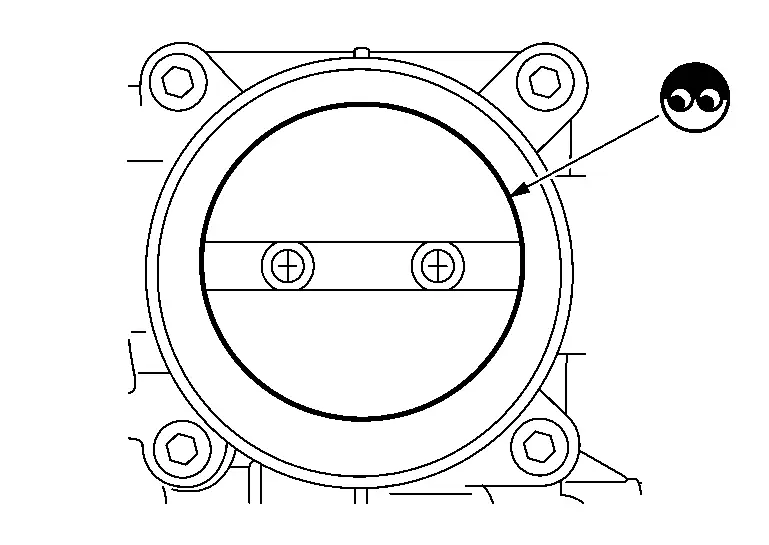
CHECK FOR INTAKE AIR LEAK
-
Stop engine and check the following for connection.
-
Air duct
-
Vacuum hoses
-
PCV hose
-
Intake air passage between air duct to intake manifold
-
-
Start engine and let it idle.
-
Listen for an intake air leak after the mass air flow sensor.
Is the inspection result normal?
YES>>
GO TO 3.
NO>>
Repair or replace error-detected parts.
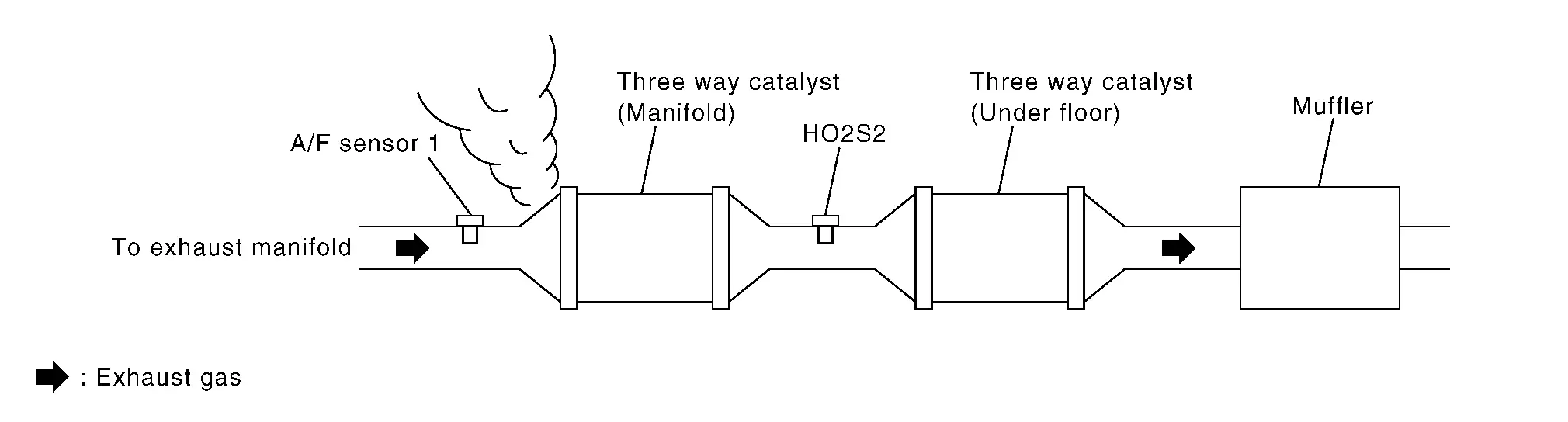
CHECK EXHAUST GAS LEAK
-
Stop engine and visually check exhaust tube, three way catalyst and muffler for dents connection.
-
Start engine and let it idle.
-
Listen for an exhaust gas leak before three way catalyst (manifold).
Is the inspection result normal?
YES>>
GO TO 4.
NO>>
Repair or replace error-detected parts.
CHECK FUEL PRESSURE
-
Release fuel pressure to zero. Refer to Work Procedure.
-
Check fuel pressure. Refer to Work Procedure.
Is the inspection result normal?
YES>>
GO TO 5.
NO>>
GO TO 9.
CHECK MASS AIR FLOW SENSOR
 With CONSULT
Check “MASS AIR FLOW SENSOR (Hz)” in “Data Monitor” mode of “ENGINE”.
For specification, refer to Mass Air Flow Sensor.
 With GST
Check mass air flow sensor signal in Service $01 using GST.
For specification, refer to Mass Air Flow Sensor.
Is the inspection result normal?
YES>>
GO TO 6.
NO>>
Check connectors for rusted terminals or loose connections in the mass air flow sensor circuit or grounds. Refer to Diagnosis Procedure.
CHECK FUNCTION OF FUEL INJECTOR
 With CONSULT
-
Start engine.
-
Perform “POWER BALANCE” in “Active Test” mode of “ENGINE”.
-
Check that each circuit produces a momentary engine speed drop.
 Without CONSULT
-
Let engine idle.
-
Listen to each fuel injector operating sound.
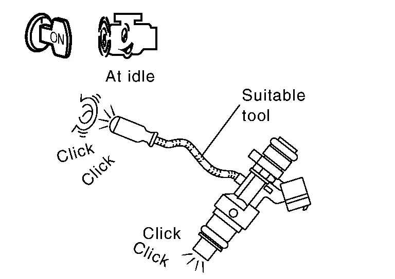
Clicking noise should be heard.
Is the inspection result normal?
YES>>
GO TO 7.
NO>>
Perform trouble diagnosis for fuel injector, refer to Component Function Check.
CHECK FUNCTION OF IGNITION COIL-I
CAUTION:
Perform the following steps in a well-ventilated area with no combustibles.
-
Turn ignition switch OFF.
-
Pull out 20A fuse (No.85) from IPDM E/R to release fuel pressure. Refer to IPDM E/R Terminal Arrangement .
 NOTE:
NOTE: CONSULT must not be used to release fuel pressure. It develops again during the following steps, if released by using CONSULT.
-
Start the engine.
-
After an engine stall, crank the engine two or three times to release all the fuel pressure.
-
Turn ignition switch OFF.
-
Disconnect all the harness connectors of ignition coil to prevent electric discharge from occurring in ignition coil.
-
Remove ignition coil assembly and spark plug of cylinder. Refer to Removal and Installation.
-
Crank engine for 5 seconds or more to remove combustion gas in the cylinder.
-
Connect spark plug and harness connector to ignition coil.
-
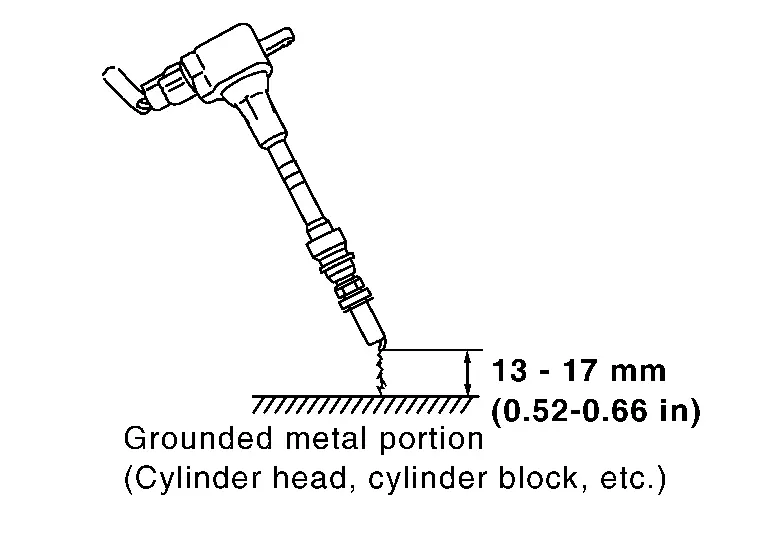
Allow a 13 – 17mm (0.52 – 0.66 in) spacing between spark plug and grounded metal portion as shown in the figure to fix the ignition coil with a rope or an equivalent.
-
Crank the engine for approximately 3 seconds to see if sparking occurs between spark plug and the grounded metal portion.
Spark should be generated. CAUTION:
-
The discharge voltage becomes 20 kV or higher. Therefore, always stay away from the spark plug and ignition coil at least 50 cm (19.7 in) during the inspection.
-
Leaving a space of more than 17mm (0.66 in) may damage the ignition coil.
 NOTE:
NOTE: When the gap is less than 13 mm (0.52 in), a the spark might be generated even if the coil is malfunctioning.
-
Is the inspection result normal?
YES>>
GO TO 8.
NO>>
GO TO 10.
CHECK COMPRESSION PRESSURE
Check compression pressure. Refer to On-Nissan Pathfinder Vehicle Service.
Is the inspection result normal?
YES>>
INSPECTION END
NO>>
Check pistons, piston rings, valves, valve seats and cylinder head gaskets.
DETECT MALFUNCTIONING PART
Check fuel hoses and fuel tubes for clogging.
Is the inspection result normal?
YES>>
Replace fuel filter and fuel pump assembly. Refer to Removal and Installation.
NO>>
Repair or replace error-detected parts.
CHECK FUNCTION OF IGNITION COIL-II
-
Turn ignition switch OFF.
-
Disconnect spark plug and connect a non-malfunctioning spark plug.
-
Crank engine for approximately 3 seconds, and recheck whether spark is generated between the spark plug and the grounded metal portion.
Spark should be generated.
Is the inspection result normal?
YES>>
GO TO 11.
NO>>
Check ignition coil, power transistor and their circuits. Refer to Component Function Check.
CHECK SPARK PLUG
Check the initial spark plug for fouling, etc.
Is the inspection result normal?
YES>>
-
Repair or clean spark plug. Refer to Removal and Installation.
-
GO TO 12.
NO>>
Replace spark plug(s) with standard type one(s). For spark plug type, refer to Exploded View.
CHECK FUNCTION OF IGNITION COIL-III
-
Reconnect the initial spark plugs.
-
Crank engine for approximately 3 seconds, and recheck whether spark is generated between the spark plug and the grounded portion.
Spark should be generated.
Is the inspection result normal?
YES>>
INSPECTION END
NO>>
Replace spark plug(s) with standard type one(s). For spark plug type, refer to Exploded View.
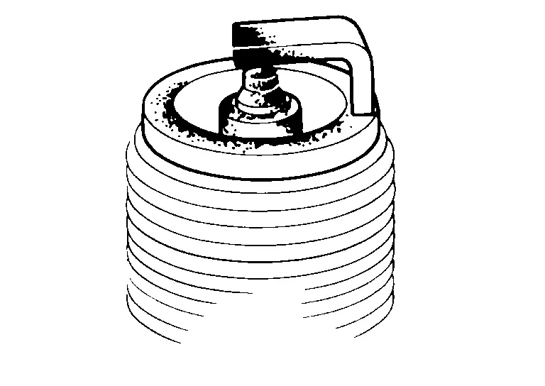
P2297 Air Fuel Ratio Sensor 1 Nissan Pathfinder R53
DTC Description
DTC DETECTION LOGIC
| DTC |
CONSULT screen terms (Trouble diagnosis content) |
DTC detection condition | ||
| P2297 | 00 |
A/F SENSOR1 (B1) (O2 Sensor Out of Range During Deceleration Bank 1 Sensor 1) |
Diagnosis condition | Engine run and fuel shut off |
| Signal | — | |||
| Threshold | Air fuel ratio(A/F) sensor 1 bank1 is out of normal range | |||
| Diagnosis delay time | — | |||
POSSIBLE CAUSE
Air fuel ratio(A/F) sensor 1 bank1
FAIL-SAFE
Not applicable
Confirmation Procedure
PRECONDITIONING
If DTC Confirmation Procedure has been previously conducted, always perform the following procedure before conducting the next test.
-
Turn ignition switch OFF and wait at least 10 seconds.
-
Turn ignition switch ON.
-
Turn ignition switch OFF and wait at least 10 seconds.
YES>>
GO TO 2.
PERFORM DTC CONFIRMATION PROCEDURE
-
Start the engine and warm it up to normal operating temperature.
-
Drive the Nissan Pathfinder vehicle a 80 km/h (50 MPH), with selecting suitable gear.
 NOTE:
NOTE:
Always keep safe driving to the first priority.
-
Release accelerator pedal completely to decelerate the Nissan Pathfinder vehicle for more than 10 seconds.
 NOTE:
NOTE:
Always keep safe driving to the first priority.
-
Check 1st trip DTC.
Is 1st trip DTC detected?
YES>>Refer to DTC Diagnosis Procedure.
NO-1>>To check malfunction symptom before repair: Refer to Intermittent Incident.
NO-2>>Confirmation after repair: INSPECTION END
DTC Diagnosis Procedure
CHECK GROUND CONNECTION
-
Turn ignition switch OFF.
-
Check ground connection E9. Refer to Circuit Inspection.
Is the inspection result normal?
YES>>GO TO 2.
NO>>Repair or replace ground connection.
CHECK AIR FUEL RATIO (A/F) SENSOR 1 POWER SUPPLY CIRCUIT
-
Disconnect A/F sensor 1 harness connector.
-
Turn ignition switch ON.
-
Check the voltage between A/F sensor 1 harness connector and ground.
A/F sensor 1 Ground Voltage Connector Terminal F72 1 Ground Battery voltage
Is the inspection result normal?
YES>>GO TO 4.
NO>>GO TO 3.
DETECT MALFUNCTIONING PART
Check the following.
-
IPDM E/R harness connector F24
-
15 A fuse (No. 82)
-
Harness for open or short between A/F sensor 1 and fuse
>>
Repair or replace harness or connectors.
CHECK A/F SENSOR 1 INPUT SIGNAL CIRCUIT FOR OPEN AND SHORT
-
Turn ignition switch OFF.
-
Disconnect ECM harness connector.
-
Check the continuity between A/F sensor 1 harness connector and ECM harness connector.
A/F sensor 1 ECM Continuity Connector Terminal Connector Terminal F72 3 F79 102 Existed 4 101 -
Check the continuity between A/F sensor 1 harness connector and ground, or ECM harness connector and ground.
A/F sensor 1 Ground Continuity Connector Terminal F72 3 Ground Not existed 4 ECM Ground Continuity Connector Terminal F79 102 Ground Not existed 101 -
Also check harness for short to power.
Is the inspection result normal?
YES>>GO TO 5.
NO>>Repair open circuit, short to ground or short to power in harness or connectors.
CHECK INTERMITTENT INCIDENT
Refer to Intermittent Incident.
Is the inspection result normal?
YES>>GO TO 6.
NO>>Repair or replace.
REPLACE AIR FUEL RATIO (A/F) SENSOR 1
Replace malfunctioning air fuel ratio (A/F) sensor 1.
CAUTION:
-
Discard any A/F sensor which has been dropped from a height of more than 0.5 m (19.7 in) onto a hard surface such as a concrete floor; use a new one.
-
Before installing new A/F sensor, clean exhaust system threads using Oxygen Sensor Thread Cleaner [commercial service tool (NI-43897-18 or NI-43897-12)] and approved Anti-seize Lubricant (commercial service tool).
>>
INSPECTION END
P25df Electric Intake Valve Timing Control Motor Nissan Pathfinder SUV
DTC Description
DTC DETECTION LOGIC
| DTC |
CONSULT screen terms (Trouble diagnosis content) |
DTC detecting condition | |||
| P25DF | 00 |
A camshaft posi control B1 (A camshaft position control bank 1) |
Diagnosis condition | Engine running at idle | |
| Signal (terminal) | Electric intake valve timing control motor signal | ||||
| Threshold | Detects electric intake valve timing control motor signal malfunction. | ||||
| Diagnosis delay time | — | ||||
POSSIBLE CAUSE
-
Harness or connectors (electric intake valve timing control motor circuit is open or shorted.)
-
Electric intake valve timing control motor
FAIL-SAFE
| Fail safe mode | Nissan Pathfinder Vehicle behavior |
|---|---|
| Device fix mode |
|
| Combustion control mode | No stratified charge combustion at starting (cold start). |
DTC CONFIRMATION PROCEDURE
PRECONDITIONING
If DTC Confirmation Procedure has been previously conducted, always perform the turn ignition switch OFF and wait at least 10 seconds before conducting the next test.
>>
GO TO 2.
PERFORM DTC CONFIRMATION PROCEDURE
-
Start the engine and let it idle.
-
Check 1st trip DTC.
Is 1st trip DTC detected?
YES>>Refer to DTC Diagnosis Procedure.
NO-1>>To check malfunction symptom before repair: Refer to Intermittent Incident.
NO-2>>Confirmation after repair: INSPECTION END
DTC Diagnosis Procedure
CHECK ELECTRIC INTAKE VALVE TIMING CONTROL ACTUATOR (BANK 1) CIRCUIT
-
Turn ignition switch OFF.
-
Disconnect electric intake valve timing control actuator (bank 1) harness connector and electric intake valve timing control module harness connector.
-
Check the continuity between electric intake valve timing control actuator (bank 1) harness connector and electric intake valve timing control module harness connector.
Electric intake valve timing control actuator (bank 1) Electric intake valve timing control module Continuity Connector Terminal Connector Terminal F87 1 F99 117 Existed 2 114 3 119 -
Also check harness for short to power and short to ground.
Is the inspection result normal?
YES>>GO TO 2.
NO>>Repair or replace error-detected parts.
CHECK INTERMITTENT INCIDENT
Check intermittent incident. Refer to Intermittent Incident.
Is the inspection result normal?
YES>>Replace electric intake valve timing control actuator (bank 1). Refer to Exploded View.
NO>>Repair or replace error-detected parts.
P2610 Ecm Internal Timer Nissan Pathfinder 2026
DTC Description
This ECM contains a timer and measures time between an ignition switch OFF and the next ignition switch ON. This enables the judging of the state of engine cooling at an engine start.
DTC DETECTION LOGIC
| DTC |
CONSULT screen terms (Trouble diagnosis content) |
DTC detection condition | ||
| P2610 | 00 |
ECM/PCM INTERNAL ENG OFF TIMER (ECM/PCM internal engine off timer performance) |
Diagnosis condition | Ignition switch ON |
| Signal (terminal) | — | |||
| Threshold |
|
|||
| Diagnosis delay time | — | |||
POSSIBLE CAUSE
-
ECM
-
ECM power supply
FAIL-SAFE
Not applicable
DTC Confirmation Procedure
INSPECTION START
It is necessary to erase permanent DTC?
YES>>GO TO 4.
NO>>GO TO 2.
PRECONDITIONING
-
Turn ignition switch OFF and wait at least 10 seconds.
-
Turn ignition switch ON.
-
Turn ignition switch OFF and wait at least 10 seconds.
TESTING CONDITION:
Before performing the following procedure, confirm that battery voltage is 12 V or more under ignition switch OFF condition.
>>
GO TO 3.
PERFORM DTC CONFIRMATION PROCEDURE-I
-
Turn ignition switch ON and wait at least 190 seconds.
-
Check 1st trip DTC.
Is DTC P2610 detected?
YES>>Proceed to Diagnosis Procedure.
NO-1>>To check malfunction symptom before repair: Refer to Intermittent Incident.
NO-2>>Confirmation after repair: INSPECTION END
PRECONDITIONING
-
Turn ignition switch OFF and wait at least 10 seconds.
-
Turn ignition switch ON.
-
Turn ignition switch OFF and wait at least 10 seconds.
TESTING CONDITION:
-
Before performing the following procedure, confirm that battery voltage is 12 V or more under ignition switch OFF condition.
-
Before performing the following procedure, check that fuel level is between 2/8 and 7/8.
>>
GO TO 5.
PERFORM DTC CONFIRMATION PROCEDURE-I
-
Turn ignition switch ON and wait at least 190 seconds.
-
Check 1st trip DTC.
Is DTC P2610 detected?
YES>>Proceed to Diagnosis Procedure.
NO>>GO TO 6.
PERFORM DTC CONFIRMATION PROCEDURE-II
CAUTION:
To start this self-diagnosis, the conditions listed bellow are required to be satisfied. Perform the following steps to satisfy the conditions.
-
Engine coolant temperature decrease by 55°C (131°F) or more during the time between an ignition switch OFF (after engine warm-up) and the second ignition switch ON.
-
A fuel temperature at the second ignition switch ON is −5°C (23°F) or more and less than 35°C (95°F).
-
The temperature difference between engine coolant and fuel is 5°C (41°F) or more.
 NOTE:
NOTE:
This self-diagnosis is not performed if the distance traveled is extremely short.
-
Turn ignition switch ON.
-
Start engine and warm it up to normal operating temperature.
-
Turn ignition switch OFF and soak the Nissan Pathfinder vehicle for at least 12 hours.
CAUTION:
-
Never turn ON the ignition switch during soaking.
-
Never open the fuel filler cap and perform refueling during soaking.
-
-
Turn ignition switch ON and wait at least 190 seconds.
-
Check 1st trip DTC.
Is DTC P2610 detected?
YES>>Proceed to Diagnosis Procedure.
NO-1>>To check malfunction symptom before repair: Refer to Intermittent Incident.
NO-2>>Confirmation after repair: INSPECTION END
Diagnosis Procedure
CHECK ECM POWER SUPPLY AND GROUND CIRCUIT
Check ECM power supply and ground circuit. Refer to Diagnosis Procedure.
Is the inspection result normal?
YES>>GO TO 2.
NO>>Repair or replace error-detected parts.
CHECK SELF-DIAGNOSTIC RESULT
Check that DTCs related to the fuel system and the cooling system are not detected.
Is the inspection result normal?
YES>>Check the DTC. Refer to DTC Index.
NO>>GO TO 3.
PERFORM DTC CONFIRMATION PROCEDURE
-
Erase DTC.
-
Perform DTC Confirmation Procedure again. Refer to DTC Description.
Is the DTC P2610 displayed again?
YES>>Replace ECM. Refer to Removal and Installation.
NO>>INSPECTION END
P2b96 Injection Pulse Nissan Pathfinder R53
DTC Description
DTC DETECTION LOGIC
| DTC |
CONSULT screen terms (Trouble diagnosis content) |
DTC detection condition | ||
| P2B96 | 00 | Injection pulse | Diagnosis condition | — |
| Signal | — | |||
| Threshold | ECM does not control fuel injection quantity properly when engine is running (except engine cold start). | |||
| Diagnosis delay time | 1 second | |||
POSSIBLE CAUSE
ECM
FAIL-SAFE
Not applicable
Confirmation Procedure
PERFORM DTC CONFIRMATION PROCEDURE
Start engine and drive the Nissan Pathfinder vehicle as per the similar conditions to Freeze Frame Data for 5 seconds.
Hold the accelerator pedal as steady as possible.
CAUTION:
Always drive Nissan Pathfinder vehicle in safe manner according to traffic conditions and obey all traffic laws when driving.
-
COOLANT TEMP
-
ENGINE SPEED
-
CAL/LD VALUE
Is DTC detected?
YES>>Proceed to DTC Diagnosis Procedure.
NO-1>>To check malfunction symptom before repair: Refer to Intermittent Incident.
NO-2>>Confirmation after repair: INSPECTION END
DTC Diagnosis Procedure
REPLACE ECM
-
Replace ECM. Refer to Removal and Installation.
-
Refer to Work Procedure.
>>
INSPECTION END
P34ac Electric Intake Valve Timing Control Actuator Nissan Pathfinder R53
DTC Description
DTC DETECTION LOGIC
| DTC |
CONSULT screen terms (Trouble diagnosis content) |
DTC detection condition | ||
| P34AC | 00 |
A camshaft posi actuator posi sens B1 (“A” camshaft position actuator position sensor circuit bank1) |
Diagnosis condition | Ignition switch ON |
| Signal (terminal) | Electric intake valve timing control motor 1 hall sensor signal | |||
| Threshold |
|
|||
| Diagnosis delay time | — | |||
POSSIBLE CAUSE
-
Harness or connectors [Electric intake valve timing (IVT) control actuator (bank 1) (motor 1 hall sensor) circuit is open or shorted.]
-
Electric IVT control actuator (bank 1) (motor 1 hall sensor)
FAIL-SAFE
| Fail safe mode | Nissan Pathfinder Vehicle behavior | |
|---|---|---|
| Device fix mode |
|
|
| Combustion control mode | Stratified charge combustion control at starting | No stratified charge combustion at starting (cold start). |
DTC Confirmation Procedure
CHECK DTC PRIORITY
If DTC P34AC is displayed with DTC P34AD, first perform the confirmation procedure (trouble diagnosis) for DTC P34AD.
Is DTC P34AD detected?
YES>>Perform diagnosis for P34AD. Refer to DTC Description.
NO>>GO TO 2.
PRECONDITIONING
If DTC Confirmation Procedure has been previously conducted, always perform the following procedure before conducting the next test.
-
Turn ignition switch OFF and wait at least 10 seconds.
-
Turn ignition switch ON.
-
Turn ignition switch OFF and wait at least 10 seconds.
TESTING CONDITION:
Before performing the following procedure, confirm that battery voltage is more than 10 V when ignition switch is ON.
>>
GO TO 3.
PERFORM DTC CONFIRMATION PROCEDURE
-
Turn ignition switch ON.
-
Check 1st trip DTC.
Is DTC P34AC detected?
YES>>Proceed to Diagnosis Procedure.
NO-1>>To check malfunction symptom before repair: Refer to Intermittent Incident.
NO-2>>Confirmation after repair: INSPECTION END
Diagnosis Procedure
CHECK DTC PRIORITY
If DTC P34AC is displayed with DTC P34AD, first perform the confirmation procedure (trouble diagnosis) for DTC P34AD.
Is DTC P34AD detected?
YES>>Perform diagnosis for P34AD. Refer to DTC Description.
NO>>GO TO 2.
CHECK ELECTRIC INTAKE VALVE TIMING (IVT) CONTROL ACTUATOR (BANK 1) HALL SENSOR POWER SUPPLY
-
Turn ignition switch OFF.
-
Disconnect electric IVT control actuator (bank 1) harness connector.
-
Turn ignition switch ON.
-
Check the voltage between electric IVT control actuator (bank 1) harness connector and ground.
+ − Voltage
(Approx.)Electric IVT control actuator (bank 1) Connector Terminal F100 4 Ground 5 V
Is the inspection result normal?
YES>>GO TO 5.
NO>>GO TO 3.
CHECK ELECTRIC IVT CONTROL MODULE POWER SUPPLY AND GROUND CIRCUIT
Check electric IVT control module power supply and ground circuit. Refer to Diagnosis Procedure.
Is the inspection result normal?
YES>>GO TO 4.
NO>>Repair or replace error-detected parts.
CHECK ELECTRIC IVT CONTROL ACTUATOR (BANK 1) HALL SENSOR POWER SUPPLY CIRCUIT
-
Turn ignition switch OFF.
-
Disconnect electric IVT control module harness connector.
-
Check the continuity between electric IVT control actuator (bank 1) harness connector and electric IVT control module harness connector.
Electric IVT control actuator (bank 1) Electric IVT control module Continuity Connector Terminal Connector Terminal F100 4 F99 106 Existed -
Check harness for short to power and short to ground.
Is the inspection result normal?
YES>>Replace electric IVT control module. Refer to Removal and Installation.
NO>>Repair or replace error-detected parts.
CHECK ELECTRIC IVT CONTROL ACTUATOR (BANK 1) HALL SENSOR GROUND CIRCUIT
-
Turn ignition switch OFF.
-
Disconnect electric IVT control module harness connector.
-
Check the continuity between electric IVT control actuator (bank 1) harness connector and electric IVT control module harness connector.
Electric IVT control actuator (bank 1) Electric IVT control module Continuity Connector Terminal Connector Terminal F100 8 F99 100 Existed -
Check harness for short to power.
Is the inspection result normal?
YES>>GO TO 6.
NO>>Repair or replace error-detected parts.
CHECK ELECTRIC IVT CONTROL ACTUATOR (BANK 1) HALL SENSOR SIGNAL CIRCUIT
-
Turn ignition switch OFF.
-
Disconnect electric IVT control module harness connector.
-
Check the continuity between electric IVT control actuator (bank 1) harness connector and electric IVT control module harness connector.
Electric IVT control actuator (bank 1) Electric IVT control module Continuity Connector Terminal Connector Terminal F100 5 F99 98 Existed 6 107 7 99 -
Check harness for short to power and short to ground.
Is the inspection result normal?
YES>>GO TO 7.
NO>>Repair or replace error-detected parts.
CHECK ELECTRIC IVT CONTROL ACTUATOR (BANK 1) PHASE SIGNAL CIRCUIT
-
Disconnect electric IVT control actuator (bank 1) harness connector.
-
Check the continuity between electric IVT control actuator (bank 1) harness connector and electric IVT control module harness connector.
Electric IVT control actuator (bank 1) Electric IVT control module Continuity Connector Terminal Connector Terminal F87 1 F99 117 Existed 2 114 3 119 -
Check harness for short to power and short to ground.
Is the inspection result normal?
YES>>GO TO 8.
NO>>Repair or replace error-detected parts.
CHECK INTERMITTENT INCIDENT
Check intermittent incident. Refer to Intermittent Incident.
Is the inspection result normal?
YES>>GO TO 9.
NO>>Repair or replace error-detected parts.
REPLACE ELECTRIC IVT CONTROL ACTUATOR (BANK 1)
-
Replace electric IVT control actuator (bank 1). Refer to Exploded View.
-
Perform DTC confirmation procedure again. Refer to DTC Description.
Is the DTC P34AC detected?
YES>>Replace electric IVT control module. Refer to Removal and Installation.
NO>>INSPECTION END

Nissan Pathfinder (R53) 2022-2026 Service Manual
Dtc/circuit Diagnosis (P2118 Throttle Control Motor ... P34ac Electric Intake Valve Timing Control Actuator)
- P2118 Throttle Control Motor
- P2119 Electric Throttle Control Actuator
- P2122 App Sensor
- P2138 App Sensor
- P219a Air Fuel Ratio
- P2297 Air Fuel Ratio Sensor 1
- P25df Electric Intake Valve Timing Control Motor
- P2610 Ecm Internal Timer
- P2b96 Injection Pulse
- P34ac Electric Intake Valve Timing Control Actuator
Contact Us
Nissan Pathfinder Info Center
Email: info@nipathfinder.com
Phone: +1 (800) 123-4567
Address: 123 Pathfinder Blvd, Nashville, TN 37214, USA
Working Hours: Mon–Fri, 9:00 AM – 5:00 PM (EST)
