Nissan Pathfinder: Dtc/circuit Diagnosis (P1575 Brake Switch ... P2101 Electric Throttle Control Function)
- P1575 Brake Switch
- P159f Active Grille Shutter
- P1603 Ecm
- P161d Immobilizer
- P1650 Starter Motor Relay 2
- P1800 Vias Control Solenoid Valve 1
- P1805 Stop Lamp Switch
- P1a10 Ecm Initial Learning Incomplete
- P2100 Throttle Control Motor Relay
- P2101 Electric Throttle Control Function
P1575 Brake Switch Nissan Pathfinder 2022
DTC Description
DTC DETECTION LOGIC
| DTC |
CONSULT screen terms (Trouble diagnosis content) | DTC detecting condition | ||
|---|---|---|---|---|
| P1575 | 00 |
BRAKE SW (BRAKE SW) |
Diagnosis condition | — |
| Signal (terminal) | CAN communication signal | |||
| Threshold | Stop lamp switch signal is sent to ECM for extremely long time while the Nissan Pathfinder vehicle is being driven. | |||
| Diagnosis delay time | — | |||
POSSIBLE CAUSE
Stop lamp switch (BCM)
FAIL-SAFE
Not applicable
DTC Confirmation Procedure
PRECONDITIONING
If DTC Confirmation Procedure has been previously conducted, always perform the following procedure before conducting the next test.
-
Turn ignition switch OFF and wait at least 10 seconds.
-
Turn ignition switch ON.
-
Turn ignition switch OFF and wait at least 10 seconds.
>>
GO TO 2.
COMPONENT FUNCTION CHECK
 With CONSULT
-
Turn ignition switch ON.
-
Select “DATA MONITOR” mode of “ENGINE” with CONSULT.
-
Check that the “BRAKE SW 2” indication as per the following condition.
Monitor item Condition Indication BRAKE SW 2 Brake pedal Fully released OFF Slightly depressed ON
 Without CONSULT
-
Turn ignition switch OFF.
-
Check the stop lamp when depressing and releasing the brake pedal.
Brake pedal Stop lamp Fully released Not illuminated Slightly depressed Illuminated
Is the inspection result normal?
YES-1>>To check malfunction symptom before repair: Refer to Intermittent Incident.
YES-2>>Confirmation after repair: INSPECTION END
NO-2>>Refer to Diagnosis Procedure.
Diagnosis Procedure
Diagnosis Procedure
PERFORM BCM DIAGNOSIS
Perform BCM diagnosis. Refer to DTC Index.
Is the inspection result normal?
YES>>INSPECTION END
NO>>Repair or replace error-detected parts.
P159f Active Grille Shutter Nissan Pathfinder 5th Gen
DTC Description
DTC DETECTION LOGIC
Active grille shutter normally stops within zone
 which is defined by zone
 (90°±10°).
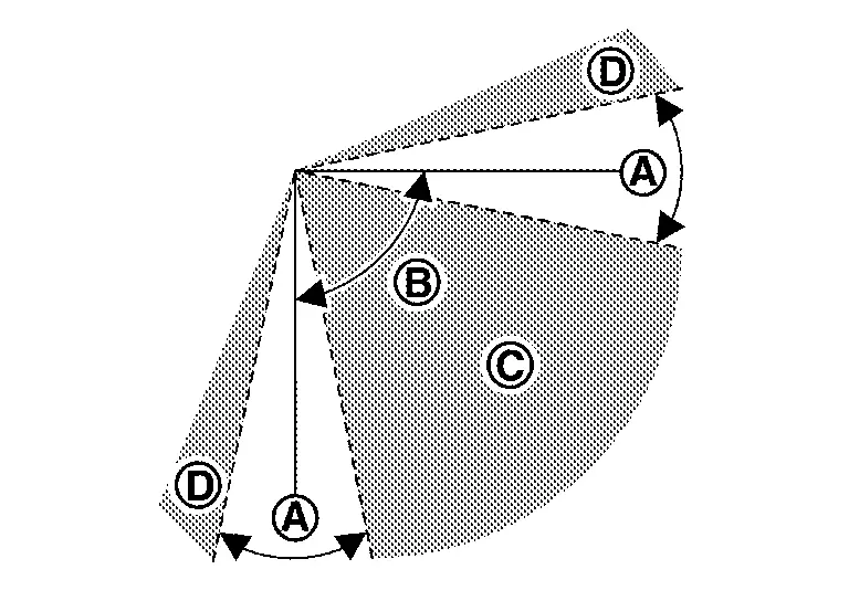
If the active grille shutter stops within zone
 stuck error is detected, and if the active grille shutter stops at position beyond zone
 overrun error is detected.
| DTC |
CONSULT screen terms (Trouble diagnosis content) |
DTC detection condition | ||
| P159F | 00 |
ACTIVE GRILLE AIR SHUTTER A (Active grille air shutter A) |
Diagnosis condition | — |
| Signal (terminal) | — | |||
| Threshold | Detects the malfunction of initial position learning or operational malfunctions for specified times. | |||
| Diagnosis delay time | — | |||
POSSIBLE CAUSE
Foreign objects interferes with active grille shutter
FAIL-SAFE
Not applicable
DTC Confirmation Procedure
CHECK DTC PRIORITY
If DTC P159F is displayed with other DTC, first perform the trouble diagnosis for other DTC.
Is applicable DTC detected?
YES>>Perform diagnosis of applicable. Refer to DTC Index.
NO>>GO TO 2.
PRECONDITIONING
If another DTC Confirmation Procedure is conducted just before this procedure, always turn ignition switch OFF and wait at least 10 seconds before conducting the next test.
TESTING CONDITION:
Before performing the following procedure, confirm that battery voltage is between 11V and 16V with ignition switch ON.
With CONSULT >>
GO TO 3.
Without CONSULT>>GO TO 5.
DTC CONFIRMATION PROCEDURE
 With CONSULT
-
Turn ignition switch OFF and wait 10 seconds or more.
-
Turn ignition switch ON.
-
Select “ACTIVE GRILLE SHUTTER” in “ACTIVE TEST”of “ENGINE” using CONSULT.
-
Touch “CALIBRTN” and wait at least 30 seconds.
-
Check the 1st trip DTC.
Is 1st trip DTC is detected?
YES>>Refer to DTC Diagnosis Procedure.
NO>>GO TO 4.
CHECK THE OPERATION OF ACTIVE GRILLE SHUTTER
After the calibration completes, check the operation of active grille shutter as follows.
| Condition | Active grille shutter |
|---|---|
| Select "CLOSE" | Open → Close |
| Select "OPEN" | Close→ Open |
Is the inspection result normal?
YES-1>>To check malfunction symptom before repair: Refer to Intermittent Incident.
YES-2>>Confirmation after repair: INSPECTION END
NO>>Proceed to DTC Diagnosis Procedure.
DTC CONFIRMATION PROCEDURE
-
Drive the Nissan Pathfinder vehicle at 30 km/h (19 MPH) or more for at least 30 seconds.
-
Check DTC.
Is 1st trip DTC detected?
YES>>Proceed to DTC Diagnosis Procedure.
NO-1>>To check malfunction symptom before repair: Refer to Intermittent Incident.
NO-2>>Confirmation after repair: INSPECTION END
DTC Diagnosis Procedure
CHECK DTC PRIORITY
If DTC P159F is displayed with other DTC, first perform the trouble diagnosis for other DTC.
Is applicable DTC detected?
YES>>Perform diagnosis of applicable. Refer to DTC Index.
NO>>GO TO 2.
CHECK ACTIVE GRILL SHUTTER
-
Turn ignition switch OFF.
-
Check if any foreign objects interferes with active grille shutter.
-
Check the installation condition of active grille shutter.
Is the inspection result normal?
YES>>INSPECTION END
NO>>Repair or replace the error-detected parts.
P1603 Ecm Nissan Pathfinder SUV
DTC Description
DTC DETECTION LOGIC
| DTC |
CONSULT screen terms (Trouble diagnosis content) |
DTC detection condition | ||
| P1603 | 00 |
CONTROL MODULE (CONTROL MODULE) |
Diagnosis condition | — |
| Signal (terminal) | — | |||
| Threshold | EEPROM (built-in microcomputer) system internal ECM does not function properly | |||
| Diagnosis delay time | — | |||
POSSIBLE CAUSE
ECM
FAIL-SAFE
Not applicable
DTC Confirmation Procedure
PRECONDITIONING
Perform the following procedure before performing DTC Confirmation Procedure.
-
Turn ignition switch OFF and wait at least 10 seconds.
-
Turn ignition switch ON.
-
Turn ignition switch OFF and wait at least 10 seconds.
>>
GO TO 2.
PERFORM DTC CONFIRMATION PROCEDURE
-
Start the engine and wait at least 10 seconds.
-
Turn ignition switch OFF and wait at least 10 seconds.
-
Repeat steps 1 and 2 for 4 times.
-
Turn ignition switch ON.
-
Erase DTC.
-
Turn ignition switch OFF and wait at least 10 seconds.
-
Start the engine and wait for 10 seconds.
-
Check 1st trip DTC.
Is 1st trip DTC detected?
YES>>Refer to DTC Diagnosis Procedure.
NO-1>>To check malfunction symptom before repair: Refer to Intermittent Incident.
NO-2>>Confirmation after repair: INSPECTION END
DTC Diagnosis Procedure
INSPECTION START
Check that the battery negative terminal is not disconnected during ignition switch ON.
Is the inspection result normal?
YES>>GO TO 3.
NO>>GO TO 2.
ERASE DTC
-
Start the engine and let it idle at least 10 seconds.
-
Turn ignition switch OFF.
-
Repeat steps 1 and 2 for 4 times.
-
Erase DTC.
-
Turn ignition switch OFF and wait at least 10 seconds.
-
Start the engine and let it idle for 10 seconds.
-
Check 1st trip DTC.
Is DTC P1603 detected again?
YES>>Replace ECM. Refer to Removal and Installation.
NO>>INSPECTION END
CHECK ECM POWER SUPPLY AND GROUND CIRCUIT
Check ECM power supply and ground circuit. Refer to Diagnosis Procedure.
Is the inspection result normal?
YES>>GO TO 4.
NO>>Repair or replace error-detected parts.
CHECK INTERMITTENT INCIDENT
Check intermittent incident. Refer to Intermittent Incident.
Is the inspection result normal?
YES>>GO TO 5.
NO>>Repair or replace error-detected parts.
PERFORM DTC CONFIRMATION PROCEDURE
-
Turn ignition switch ON.
-
Erase DTC.
-
Perform DTC confirmation procedure. Refer to DTC Description.
Is the DTC P1603 detected again?
YES>>Replace ECM. Refer to Removal and Installation.
NO>>INSPECTION END
P161d Immobilizer Nissan Pathfinder 2022
DTC Description
DTC DETECTION LOGIC
 NOTE:
NOTE:
DTC P161D is displayed with another ECU.
Perform the trouble diagnosis for the corresponding DTC of another ECU. Refer to DTC Description.
FAIL-SAFE
Not applicable
P1650 Starter Motor Relay 2 Nissan Pathfinder R53
DTC Description
DTC DETECTION LOGIC
| DTC |
CONSULT screen terms (Trouble diagnosis content) | DTC detection condition | |||
|---|---|---|---|---|---|
| P1650 | 00 |
STR MTR RELAY 2 (Starter relay circuit) |
A | Diagnosis condition | — |
| Signal (terminal) | CAN communication signal | ||||
| Threshold | Starter relay is stuck ON. | ||||
| Diagnosis delay time | — | ||||
| B | Diagnosis condition | — | |||
| Signal (terminal) | CAN communication signal | ||||
| Threshold | Starter relay power supply circuit is excessively high voltage. | ||||
| Diagnosis delay time | — | ||||
| C | Diagnosis condition | — | |||
| Signal (terminal) | CAN communication signal | ||||
| Threshold | Starter relay circuit is excessively low voltage | ||||
| Diagnosis delay time | — | ||||
POSSIBLE CAUSE A
-
Starter relay
-
IPDM E/R
POSSIBLE CAUSE B
-
Harness and connectors
(Between IPDM E/R harness connector and battery is open.)
-
IPDM E/R
POSSIBLE CAUSE C
-
Harness and connectors
(Starter relay circuit is open or shorted.)
-
IPDM E/R
FAIL-SAFE
Engine Control System
Not applicable
Stop/Start System
When ECM detects error, ECM detects DTC, prohibits the start/stop system operation, and display the stop/start warning indicator.
When ECM detects error while operating the stop/start system, ECM restarts the engine.
DTC Confirmation Procedure
CHECK DTC PRIORITY
If DTC P1650 is displayed with DTC U1000 or P0607, first perform the confirmation procedure (trouble diagnosis) for DTC U1000 or P0607.
Is DTC U1000 or P0607 detected?
YES>>Perform diagnosis of applicable.
-
DTC U1000: Refer to DTC Description.
-
DTC P0607: Refer to DTC Description.
GO TO 2.
PRECONDITIONING
If the other DTC Confirmation Procedure is performed right before this procedure, the ignition switch must be turned OFF and wait for 10 seconds or more to start this procedure.
 NOTE:
NOTE:
Before performing the following procedure, check that battery voltage is 12 V or more with ignition switch ON.
>>
GO TO 3.
PERFORM DTC CONFIRMATION PROCEDURE-1
-
Turn ignition switch OFF and wait at least 10 seconds.
-
Turn ignition switch ON and wait at least 30 seconds
-
Turn ignition switch OFF, wait at least 10 seconds and then turn ON.
-
Check 1st trip DTC.
Is 1st trip DTC detected?
YES>>Proceed to Diagnosis Procedure.
NO>>GO TO 4.
PERFORM DTC CONFIRMATION PROCEDURE-2
 With CONSULT
-
Start the engine and warm it up to normal operating temperature.
-
Select “AUTO STOP START” in “ACTIVE TEST” mode of “ENGINE” using CONSULT.
-
Touch “START” and operate stop/start system. (engine stop.)
-
Touch “CANCEL” and restart the engine.
 Without CONSULT
Activate stop/start system. Refer to System Description.
CAUTION:
Always drive Nissan Pathfinder vehicle at a safe speed.
Is stop/start system activated normal?
YES-1>>To check malfunction symptom before repair: Refer to Intermittent Incident.
YES-2>>Confirmation after repair: INSPECTION END
NO>>Proceed to Diagnosis Procedure.
Diagnosis Procedure
CHECK DTC PRIORITY
If DTC P1650 is displayed with DTC U1000 or P0607, first perform the confirmation procedure (trouble diagnosis) for DTC U1000 or P0607.
Is DTC U1000 or P0607 detected?
YES>>Perform diagnosis of applicable.
-
DTC U1000: Refer to DTC Description.
-
DTC P0607: Refer to DTC Description.
GO TO 2.
CHECK IPDM E/R POWER SUPPLY CIRCUIT
Check IPDM E/R power supply circuit. Refer to Diagnosis Procedure.
Is the inspection result normal?
YES>>GO TO 3.
NO>>Repair or replace error-detected parts.
CHECK INTERMITTENT INCIDENT
Check intermittent incident. Refer to Intermittent Incident.
Is the inspection result normal?
YES>>GO TO 4.
NO>>Repair or replace error-detected parts.
REPLACE IPDM E/R
Replace IPDM E/R. Refer to Removal and Installation.
>>
INSPECTION END
P1800 Vias Control Solenoid Valve 1 Nissan Pathfinder R53
DTC Description
DTC DETECTION LOGIC
| DTC |
CONSULT screen terms (Trouble diagnosis content) |
DTC detection condition | ||
| P1800 | 00 |
VIAS S/V CIRC-B1 (VIAS solenoid valve circuit bank 1) |
Diagnosis condition | Ignition switch ON |
| Signal (terminal) | VIAS control solenoid valve 1 signal | |||
| Threshold | An excessively low or high voltage signal is sent to ECM through the VIAS control solenoid valve 1 | |||
| Diagnosis delay time | — | |||
POSSIBLE CAUSE
-
Harness or connectors (VIAS control solenoid valve 1 circuit is open or shorted.)
-
VIAS control solenoid valve 1
FAIL-SAFE
Not applicable
DTC Confirmation Procedure
CONDITIONING
If DTC Confirmation Procedure has been previously conducted, always perform the following before conducting the next test.
-
Turn ignition switch OFF and wait at least 10 seconds.
-
Turn ignition switch ON.
-
Turn ignition switch OFF and wait at least 10 seconds.
TESTING CONDITION:
Before performing the following procedure, confirm battery voltage is more than 11 V at idle.
>>
GO TO 2.
PERFORM DTC CONFIRMATION PROCEDURE
-
Start engine and let it idle for at least 5 seconds.
-
Check 1st trip DTC.
Is DTC P1800 detected?
YES>>Proceed to Diagnosis Procedure.
NO-1>>To check malfunction symptom before repair: Refer to Intermittent Incident.
NO-2>>Confirmation after repair: INSPECTION END
Diagnosis Procedure
CHECK VIAS CONTROL SOLENOID VALVE 1 POWER SUPPLY
-
Turn ignition switch OFF.
-
Disconnect VIAS control solenoid valve 1 harness connector.
-
Turn ignition switch ON.
-
Check the voltage between VIAS control solenoid valve 1 harness connector and ground.
+ − Voltage VIAS control solenoid valve 1 Connector Terminal F66 1 Ground Battery voltage
Is the inspection result normal?
YES>>GO TO 3.
NO>>GO TO 2.
CHECK VIAS CONTROL SOLENOID VALVE 1 POWER SUPPLY CIRCUIT
-
Turn ignition switch OFF.
-
Disconnect IPDM E/R harness connector.
-
Check the continuity between VIAS control solenoid valve 1 harness connector and IPDM E/R harness connector.
VIAS control solenoid valve 1 IPDM E/R Continuity Connector Terminal Connector Terminal F66 1 F24 78 Existed -
Also check harness for short to ground.
Is the inspection result normal?
YES>>Perform the trouble diagnosis for power supply circuit.
NO>>Repair or replace error-detected parts.
CHECK VIAS CONTROL SOLENOID VALVE 1 OUTPUT SIGNAL CIRCUIT
-
Turn ignition switch OFF.
-
Disconnect ECM harness connector.
-
Check the continuity between VIAS control solenoid valve 1 harness connector and ECM harness connector.
VIAS control solenoid valve 1 ECM Continuity Connector Terminal Connector Terminal F66 2 F79 163 Existed -
Also check harness for short to ground and short to power.
Is the inspection result normal?
YES>>GO TO 4.
NO>>Repair or replace error-detected parts.
CHECK VIAS CONTROL SOLENOID VALVE 1
Check VIAS control solenoid valve 1. Refer to Component Inspection.
Is the inspection result normal?
YES>>INSPECTION END
NO>>Replace VIAS control solenoid valve 1. Refer to Exploded View.
Component Inspection
CHECK VIAS CONTROL SOLENOID VALVE 1
 With CONSULT
-
Turn ignition switch OFF.
-
Reconnect all harness connectors disconnected.
-
Disconnect vacuum hoses connected to VIAS control solenoid valve 1.
-
Turn ignition switch ON.
-
On CONSULT screen, select “ENGINE”>>“Active Test”>>“VIAS S/V-1”.
-
Check air passage continuity and operation delay time under the following conditions.
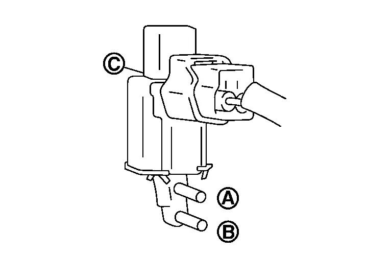
|
Condition (VIAS S/V-1) | Air passage continuity between
 and and
 |
Air passage continuity between and and
 |
|---|---|---|
| ON | Existed | Not existed |
| OFF | Not existed | Existed |
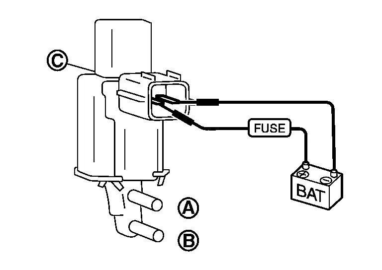
 Without CONSULT
-
Turn ignition switch OFF.
-
Disconnect VIAS control solenoid valve 1 harness connector.
-
Disconnect vacuum hoses connected to VIAS volume control solenoid valve 1.
-
Check air passage continuity and operation delay time under the following conditions.
| Condition | Air passage continuity between
 and and
 |
Air passage continuity between and and
 |
|---|---|---|
| 12 V direct current supply between terminals 1 and 2 | Existed | Not existed |
| No supply | Not existed | Existed |
Is the inspection result normal?
YES>>INSPECTION END
NO>>Replace VIAS control solenoid valve 1. Refer to Exploded View.
P1805 Stop Lamp Switch Nissan Pathfinder 2026
DTC Description
DTC DETECTION LOGIC
DTC DETECTION LOGIC
| DTC |
CONSULT screen terms (Trouble diagnosis content) |
DTC detection condition | ||
| P1805 | 00 |
BRAKE SW/CIRCUIT (Brake switch/circuit) |
Diagnosis condition | — |
| Signal (terminal) | CAN communication signal | |||
| Threshold | A stop lamp switch signal is not sent to ECM while the Nissan Pathfinder vehicle is driving | |||
| Diagnosis delay time | — | |||
POSSIBLE CAUSE
Stop lamp switch (BCM)
FAIL-SAFE
Not applicable
DTC Confirmation Procedure
PERFORM DTC CONFIRMATION PROCEDURE
-
Turn ignition switch ON.
-
Fully depress the brake pedal for at least 5 seconds.
-
Erase the DTC.
-
Check 1st trip DTC.
Is 1st trip DTC detected?
YES>>Proceed to Diagnosis Procedure.
NO-1>>To check malfunction symptom before repair: Refer to Intermittent Incident.
NO-2>>Confirmation after repair: INSPECTION END
Diagnosis Procedure
PERFORM BCM DIAGNOSIS
Perform BCM diagnosis. Refer to DTC Index.
Is the inspection result normal?
YES>>INSPECTION END
NO>>Repair or replace error-detected parts.
P1a10 Ecm Initial Learning Incomplete Nissan Pathfinder 2026
DTC Description
DTC DETECTION LOGIC
| DTC |
CONSULT screen terms (Trouble diagnosis content) |
DTC detection condition | ||
| P1A10 | 00 |
ECM initial learning Incomplete (ECM initial learning Incomplete) |
Diagnosis condition | Ignition switch ON |
| Signal (terminal) | — | |||
| Threshold | When drive distance will be less than 96 km (60 miles) and ECM keeps initial state to replace ECM will indicate DTC. | |||
| Diagnosis delay time | — | |||
POSSIBLE CAUSE
ECM initial learning not complete
FAIL-SAFE
Not applicable
DTC Confirmation Procedure
PRECONDITIONING
If DTC Confirmation Procedure has been previously conducted, always turn ignition switch OFF and wait at least 10 seconds before conducting the next test.
TESTING CONDITION:
-
Before performing the following procedure, confirm that battery voltage is more than 11 V at idle.
>>
GO TO 2.
PERFORM DTC CONFIRMATION PROCEDURE
 With CONSULT
-
Turn ignition switch ON.
-
Check 1st trip DTC.
Is 1st trip DTC detected?
YES>>Proceed to DTC Diagnosis Procedure.
NO-1>>To check malfunction symptom before repair: Refer to Intermittent Incident.
NO-2>>Confirmation after repair: INSPECTION END
DTC Diagnosis Procedure
PERFORM ECM INITIAL LEARNING
-
Turn ignition switch ON. (Do not start the engine.)
-
Set selector lever to P position and apply parking brake.
-
Accelerator pedal is fully depressed and erase DTC.
-
Turn ignition switch OFF.
-
Check that no DTC is detected.
>>
INSPECTION END
P2100 Throttle Control Motor Relay Nissan Pathfinder SUV
DTC Description
DTC DETECTION LOGIC
| DTC |
CONSULT screen terms (Trouble diagnosis content) |
DTC detection condition | ||
| P2100 | 00 |
ETC MOT PWR-B1 (Throttle control motor relay circuit open) |
Diagnosis condition | Engine running at idle |
| Signal (terminal) | Throttle control motor relay signal | |||
| Threshold | A voltage of power source for throttle control motor is excessively low | |||
| Diagnosis delay time | — | |||
POSSIBLE CAUSE
-
Harness or connectors (Throttle control motor relay circuit is open)
-
Throttle control motor relay
FAIL-SAFE
| Fail safe mode | Nissan Pathfinder Vehicle behavior | |
|---|---|---|
| Device fix mode |
|
|
| Electric throttle control cancel mode | ECM stops the electric throttle control actuator control, throttle valve is maintained at a fixed opening (approx. 5 degrees) by the return spring. | |
DTC Confirmation Procedure
PRECONDITIONING
If DTC Confirmation Procedure has been previously conducted, always perform the following procedure before conducting the next test.
-
Ignition switch OFF and wait at least 10 seconds.
-
Ignition switch ON.
-
Ignition switch OFF and wait at least 10 seconds.
TESTING CONDITION:
Before performing the following procedure, confirm that battery voltage is more than 8 V.
Which DTC is detected?
>>GO TO 2.
PERFORM DTC CONFIRMATION PROCEDURE FOR DTC P2100
-
Ignition switch ON and wait at least 2 seconds.
-
Start engine and let it idle for 5 seconds.
-
Check DTC.
Is DTC P2100 detected?
YES>>Proceed to Diagnosis Procedure.
NO>>INSPECTION END
Diagnosis Procedure
CHECK THROTTLE CONTROL MOTOR RELAY POWER SUPPLY
-
Ignition switch ON.
-
Check the voltage between ECM harness connector and ground.
+ − Voltage ECM Connector Terminal Connector Terminal F79 139 E32 204 Battery voltage
Is the inspection result normal?
YES>>GO TO 3.
NO>>GO TO 2.
CHECK THROTTLE CONTROL MOTOR RELAY POWER SUPPLY CIRCUIT
-
Disconnect ECM harness connector.
-
Disconnect IPDM E/R harness connector.
-
Check the continuity between ECM harness connector and IPDM E/R harness connector.
ECM IPDM E/R Continuity Connector Terminal Connector Terminal F79 139 F24 67 Existed -
Also check harness for short to ground.
Is the inspection result normal?
YES>>Perform the trouble diagnosis for power supply circuit.
NO>>Repair or replace error-detected parts.
CHECK FUSE
-
Ignition switch OFF.
-
Check that the following fuse is not blowing.
Location Fuse No. Capacity IPDM E/R #80 15A
Is the fuse blown (open)?
YES>>Replace the fuse after repairing the applicable circuit.
NO>>GO TO 4.
CHECK THROTTLE CONTROL MOTOR RELAY INPUT SIGNAL
Check the voltage between ECM harness connector and ground as per the following conditions.
| ECM | Condition |
Voltage (Approx.) | |||
|---|---|---|---|---|---|
| + | − | ||||
| Connector | Terminal | Connector | Terminal | ||
| F79 | 95 | E32 | 204 | Ignition switch: OFF | 0 V |
| Ignition switch: ON | Battery voltage | ||||
Is the inspection result normal?
YES>>INSPECTION END
NO>>GO TO 5.
CHECK THROTTLE CONTROL MOTOR RELAY INPUT SIGNAL CIRCUIT
-
Ignition switch OFF.
-
Disconnect ECM harness connector.
-
Disconnect IPDM E/R harness connector.
-
Check the continuity between ECM harness connector and IPDM E/R harness connector.
ECM IPDM E/R Continuity Connector Terminal Connector Terminal F79 95 F24 72 Existed -
Also check harness for short to power and short to ground.
Is the inspection result normal?
YES>>Perform the trouble diagnosis for power supply circuit.
NO>>Repair or replace error-detected parts.
P2101 Electric Throttle Control Function Nissan Pathfinder 2022
DTC Description
DTC DETECTION LOGIC
| DTC |
CONSULT screen terms (Trouble diagnosis content) |
DTC detection condition | ||
| P2101 | 00 |
ETC FNCTN/CIRC-B1 (Electric throttle control performance) |
Diagnosis condition | Engine running at idle |
| Signal (terminal) | Throttle control motor signal | |||
| Threshold | Electric throttle control function does not operate properly | |||
| Diagnosis delay time | — | |||
POSSIBLE CAUSE
-
Harness or connectors (Throttle control motor circuit is open or shorted)
-
Electric throttle control actuator
FAIL-SAFE
| Fail safe mode | Nissan Pathfinder Vehicle behavior | |
|---|---|---|
| Device fix mode |
|
|
| Electric throttle control cancel mode | ECM stops the electric throttle control actuator control, throttle valve is maintained at a fixed opening (approx. 5 degrees) by the return spring. | |
DTC Confirmation Procedure
CHECK DTC PRIORITY
If DTC P2101 is displayed with DTC P2100 or P2119, first perform the confirmation procedure (trouble diagnosis) for DTC P2100 or P2119.
Is DTC P2100 or P2119 detected?
YES>>
Perform diagnosis of applicable.
-
DTC P2100: Refer to DTC Description.
-
DTC P2119: Refer to DTC Description.
NO>>
GO TO 2.
PRECONDITIONING
If DTC Confirmation Procedure has been previously conducted, always perform the following procedure before conducting the next test.
-
Turn ignition switch OFF and wait at least 10 seconds.
-
Turn ignition switch ON.
-
Turn ignition switch OFF and wait at least 10 seconds.
TESTING CONDITION:
Before performing the following procedure, confirm that battery voltage is more than 11 V when engine is running.
>>
GO TO 3.
PERFORM DTC CONFIRMATION PROCEDURE
-
Turn ignition switch ON and wait at least 2 seconds.
-
Start engine and let it idle for 5 seconds.
-
Check DTC.
Is DTC P2101 detected?
YES>>
Proceed to Diagnosis Procedure.
NO-1>>
To check malfunction symptom before repair: Refer to Intermittent Incident.
NO-2>>
Confirmation after repair: INSPECTION END
Diagnosis Procedure
CHECK DTC PRIORITY
If DTC P2101 is displayed with DTC P2100 or P2119, first perform the confirmation procedure for DTC P2100 or P2119.
Is DTC P2100 or P2119 detected?
YES>>
Perform diagnosis of applicable.
-
DTC P2100: Refer to DTC Description.
-
DTC P2119: Refer to DTC Description.
NO>>
GO TO 2.
CHECK THROTTLE CONTROL MOTOR RELAY INPUT SIGNAL
Check the voltage between ECM harness connector terminals as per the following conditions.
| ECM | Condition |
Voltage (Approx.) |
|||
|---|---|---|---|---|---|
| + | − | ||||
| Connector | Terminal | Connector | Terminal | ||
| F79 | 139 | E32 | 204 | Ignition switch: OFF | 0 V |
| Ignition switch: ON | Battery voltage | ||||
Is the inspection result normal?
YES>>
GO TO 5.
NO>>
GO TO 3.
CHECK THROTTLE CONTROL MOTOR RELAY INPUT SIGNAL CIRCUIT
-
Turn ignition switch OFF.
-
Disconnect ECM harness connector.
-
Disconnect IPDM E/R harness connector.
-
Check the continuity between ECM harness connector and IPDM E/R harness connector.
ECM IPDM E/R Continuity Connector Terminal Connector Terminal F79 139 F24 67 Existed -
Also check harness for short to power and short to ground.
Is the inspection result normal?
YES>>
GO TO 4.
NO>>
Repair or replace error-detected parts.
CHECK THROTTLE CONTROL MOTOR RELAY POWER SUPPLY CIRCUIT
-
Check the continuity between ECM harness connector and IPDM E/R harness connector.
ECM IPDM E/R Continuity Connector Terminal Connector Terminal F79 95 F24 72 Existed -
Also check harness for short to ground.
Is the inspection result normal?
YES>>
Perform the trouble diagnosis for power supply circuit.
NO>>
Repair or replace error-detected parts.
CHECK THROTTLE CONTROL MOTOR OUTPUT SIGNAL CIRCUIT
-
Turn ignition switch OFF.
-
Disconnect electric throttle control actuator harness connector.
-
Disconnect ECM harness connector.
-
Check the continuity between electric throttle control actuator harness connector and ECM harness connector.
Electric throttle control actuator ECM Continuity Connector Terminal Connector Terminal F50 2 F79 148 Existed 147 Not existed 1 148 Not existed 147 Existed -
Also check harness for short to power and short to ground.
Is the inspection result normal?
YES>>
GO TO 6.
NO>>
Repair or replace error-detected parts.
CHECK ELECTRIC THROTTLE CONTROL ACTUATOR VISUALLY
-
Remove air duct hose and resonator assembly. Refer to Exploded View.
-
Check if foreign matter is caught between the throttle valve and the housing.
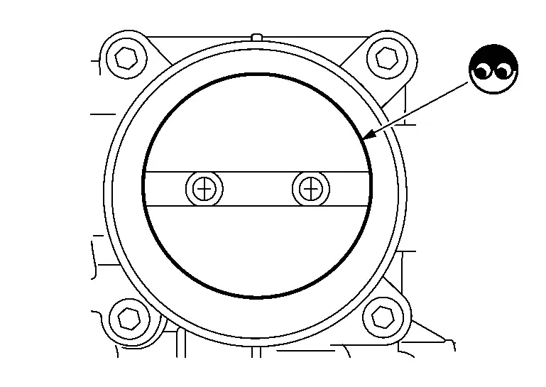
Is the inspection result normal?
YES>>
GO TO 7.
NO>>
Remove the foreign matter and clean the electric throttle control actuator inside, then perform throttle valve closed position learning. Refer to Description.
CHECK THROTTLE CONTROL MOTOR
Check the throttle control motor. Refer to Component Inspection.
Is the inspection result normal?
YES>>
INSPECTION END
NO>>
Replace electric throttle control actuator. Refer to Exploded View.
Component Inspection
CHECK THROTTLE CONTROL MOTOR
-
Turn ignition switch OFF.
-
Disconnect electric throttle control actuator harness connector.
-
Check the resistance between electric throttle control actuator terminals as per the following.
Electric throttle control actuator Condition Resistance Terminal 1 2 Temperature [°C (°F)] 25 (77) 1 – 15 Ω
Is the inspection result normal?
YES>>
INSPECTION END
NO>>
Replace electric throttle control actuator. Refer to Exploded View.

Nissan Pathfinder (R53) 2022-2026 Service Manual
Dtc/circuit Diagnosis (P1575 Brake Switch ... P2101 Electric Throttle Control Function)
- P1575 Brake Switch
- P159f Active Grille Shutter
- P1603 Ecm
- P161d Immobilizer
- P1650 Starter Motor Relay 2
- P1800 Vias Control Solenoid Valve 1
- P1805 Stop Lamp Switch
- P1a10 Ecm Initial Learning Incomplete
- P2100 Throttle Control Motor Relay
- P2101 Electric Throttle Control Function
Contact Us
Nissan Pathfinder Info Center
Email: info@nipathfinder.com
Phone: +1 (800) 123-4567
Address: 123 Pathfinder Blvd, Nashville, TN 37214, USA
Working Hours: Mon–Fri, 9:00 AM – 5:00 PM (EST)
