Nissan Pathfinder: Dtc/circuit Diagnosis (P0441 Evap Control System ... P0524 Engine Oil Pressure)
- P0441 Evap Control System
- P0443 Evap Canister Purge Volume Control Solenoid Valve
- P0447 Evap Canister Vent Control Valve
- P0450 Evap Control System Pressure Sensor
- P0461 Fuel Level Sensor
- P0500 Vss
- P0506 Isc System
- P050a Cold Start Control
- P0520 Eop Sensor
- P0524 Engine Oil Pressure
P0441 Evap Control System Nissan Pathfinder 2022
DTC Description
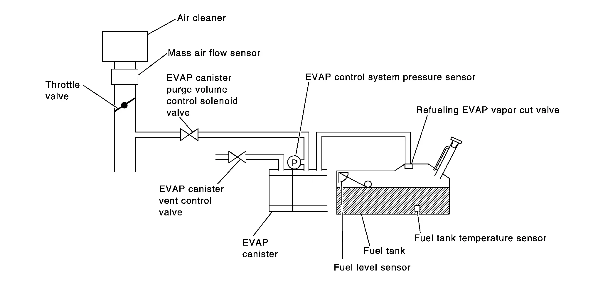
In this evaporative emission (EVAP) control system, purge flow occurs during non-closed throttle conditions. Purge volume is related to air intake volume. Under normal purge conditions (non-closed throttle), the EVAP canister purge volume control solenoid valve is open to admit purge flow. Purge flow exposes the EVAP control system pressure sensor to intake manifold vacuum.
Under normal conditions (non-closed throttle), sensor output voltage indicates if pressure drop and purge flow are adequate. If not, a malfunction is determined.
DTC DETECTION LOGIC
| DTC |
CONSULT screen terms (Trouble diagnosis content) |
DTC detection condition | ||
| P0441 | 00 |
EVAP PURG FLOW/MON (Evaporative emission system incorrect purge flow) |
Diagnosis condition | — |
| Signal (terminal) | — | |||
| Threshold | EVAP control system does not operate properly, EVAP control system has a leak between intake manifold and EVAP control system pressure sensor | |||
| Diagnosis delay time | — | |||
POSSIBLE CAUSE
-
EVAP canister purge volume control solenoid valve stuck closed
-
EVAP control system pressure sensor and the circuit
-
Loose, disconnected or improper connection of rubber tube
-
Blocked rubber tube
-
Cracked EVAP canister
-
EVAP canister purge volume control solenoid valve circuit
-
Accelerator pedal position sensor
-
Blocked purge port
-
EVAP canister vent control valve
FAIL-SAFE
Not applicable
DTC Confirmation Procedure
CHECK DTC PRIORITY
If DTC P0441 is displayed with other DTC such as P2122, P2123, P2127, P2128 or P2138, first perform the confirmation procedure (trouble diagnosis) for other DTC.
Is DTC P2122, P2123, P2127, P2128 or P2138 detected?
YES>>
Perform diagnosis of applicable.
-
DTC P2122: Refer to DTC Description.
-
DTC P2123: Refer to DTC Description.
-
DTC P2127: Refer to DTC Description.
-
DTC P2128: Refer to DTC Description.
-
DTC P2138: Refer to DTC Description.
NO>>
GO TO 2.
INSPECTION START
Do you have CONSULT?
YES>>
GO TO 3.
NO>>
GO TO 7.
PRECONDITIONING
If DTC Confirmation Procedure has been previously conducted, always perform the following procedure before conducting the next test.
-
Turn ignition switch OFF and wait at least 10 seconds.
-
Turn ignition switch ON.
-
Turn ignition switch OFF and wait at least 10 seconds.
TESTING CONDITION:
Always perform test at a temperature of 5°C (41°F) or more.
>>
GO TO 4.
PERFORM DTC CONFIRMATION PROCEDURE-I
 With CONSULT
-
Start engine and warm it up to normal operating temperature.
-
Turn ignition switch OFF and wait at least 10 seconds.
-
Turn ignition switch ON.
-
Turn ignition switch OFF and wait at least 10 seconds.
-
Start engine and let it idle for at least 70 seconds.
-
On CONSULT screen, select “ENGINE”>>“DTC Work Support”>>“EVAPORATIVE SYSTEM”>>“PURG FLOW P0441”.
-
Touch “START”.
Is “COMPLETED” displayed on CONSULT screen?
YES>>
GO TO 6.
NO>>
GO TO 5.
PERFORM DTC CONFIRMATION PROCEDURE-II
When the following conditions are met, “TESTING” will be displayed on the CONSULT screen. Maintain the conditions continuously until “TESTING” changes to “COMPLETED”. (It will take at least 35 seconds.)
| Selector lever | Suitable position |
| VHCL SPEED SE | 32 – 120 km/h (20 – 75 mph) |
| ENG SPEED | 500 – 3,000 rpm |
| B/FUEL SCHDL | 1.25 – 7.6 msec |
| COOLAN TEMP/S | More than 0°C (32°F) |
CAUTION:
Always drive Nissan Pathfinder vehicle at a safe speed.
Is “COMPLETED” displayed on CONSULT screen?
YES>>
GO TO 6.
NO>>
Perform DTC CONFIRMATION PROCEDURE again. GO TO 3.
PERFORM DTC CONFIRMATION PROCEDURE-III
Touch “SELF-DIAG RESULTS”.
Is “OK” displayed on CONSULT screen?
YES-1>>
To check malfunction symptom before repair: Refer to Intermittent Incident.
YES-2>>
Confirmation after repair: INSPECTION END
NO>>
Proceed to Diagnosis Procedure.
PERFORM COMPONENT FUNCTION CHECK
 NOTE:
NOTE:
Use component function check to check the overall monitoring function of the EVAP control system purge flow monitoring. During this check, a 1st trip DTC might not be confirmed.
 Without CONSULT
-
Lift up drive wheels.
-
Start engine (VDC switch OFF) and warm it up to normal operating temperature.
-
Turn ignition switch OFF and wait at least 10 seconds.
-
Turn ignition switch ON.
-
Turn ignition switch OFF and wait at least 10 seconds.
-
Start engine and wait at least 70 seconds.
-
Set voltmeter probes to ECM harness connector terminals as per the following.
ECM Connector + − Terminal E32 173 200 -
Check EVAP control system pressure sensor value at idle speed and note it.
-
Establish and maintain the following conditions for at least 1 minute.
Air conditioner switch ON Headlamp switch ON Rear window defogger switch ON Engine speed Approx. 3,000 rpm Gear position Any position other than P, N or R -
Verify that EVAP control system pressure sensor value stays 0.1 V less than the value at idle speed (measured at step 8) for at least 1 second.
Is the inspection result normal?
YES-1>>
To check malfunction symptom before repair: Refer to Intermittent Incident.
YES-2>>
Confirmation after repair: INSPECTION END
NO>>
Proceed to Diagnosis Procedure.
Diagnosis Procedure
CHECK DTC PRIORITY
If DTC P0441 is displayed with other DTC such as P2122, P2123, P2127, P2128 or P2138, first perform the confirmation procedure (trouble diagnosis) for other DTC.
Is DTC P2122, P2123, P2127, P2128 or P2138 detected?
YES>>
Perform diagnosis of applicable.
-
DTC P2122: Refer to DTC Description.
-
DTC P2123: Refer to DTC Description.
-
DTC P2127: Refer to DTC Description.
-
DTC P2128: Refer to DTC Description.
-
DTC P2138: Refer to DTC Description.
NO>>
GO TO 2.
CHECK EVAP CANISTER
-
Turn ignition switch OFF.
-
Check EVAP canister for cracks.
Is the inspection result normal?
YES-1>>
With CONSULT: GO TO 3.
YES-2>>
Without CONSULT: GO TO 4.
NO>>
Replace EVAP canister. Refer to Removal and Installation.
CHECK PURGE FLOW
 With CONSULT
-
Disconnect vacuum hose connected to EVAP canister purge volume control solenoid valve at EVAP service port.
-
Start engine and let it idle.
-
On CONSULT screen, select “ENGINE”>>“Active Test”>>“PURG VOL CONT/V”.
-
Touch “Qd” and “Qu” on CONSULT screen to adjust “PURG VOL C/V” opening and check vacuum existence.
PURG VOL C/V Vacuum 100% Existed 0% Not existed
Is the inspection result normal?
YES>>
GO TO 8.
NO>>
GO TO 5.
CHECK PURGE FLOW
 Without CONSULT
-
Start engine and warm it up to normal operating temperature.
-
Stop engine.
-
Disconnect vacuum hose connected to EVAP canister purge volume control solenoid valve at EVAP service port and install vacuum gauge. For the location of EVAP service port, refer to Component Parts Location.
-
Start engine and let it idle.
Do not depress accelerator pedal even slightly.
-
Check vacuum gauge indication before 60 seconds passed after starting engine.
Vacuum should not exist. -
Revving engine up to 2,000rpm after 100 seconds passed after starting engine.
Vacuum should exist.
Is the inspection result normal?
YES>>
GO TO 8.
NO>>
GO TO 5.
CHECK EVAP PURGE LINE
-
Turn ignition switch OFF.
-
Check EVAP purge line for improper connection or disconnection.
Refer to System Description.
Is the inspection result normal?
YES>>
GO TO 6.
NO>>
Repair it.
CHECK EVAP PURGE HOSE AND PURGE PORT
-
Disconnect purge hoses connected to EVAP service port
 and EVAP canister purge volume control solenoid valve
  .
.
-
Blow air into each hose and EVAP purge port
 .
. -
Check that air flows freely.
Is the inspection result normal?
YES-1>>
With CONSULT: GO TO 7.
YES-2>>
Without CONSULT: GO TO 8.
NO>>
Repair or clean hoses and/or purge port.
CHECK EVAP CANISTER PURGE VOLUME CONTROL SOLENOID VALVE
 With CONSULT
-
Start engine.
-
On CONSULT screen, select “ENGINE”>>“Active Test”>>“PURG VOL CONT/V”.
-
Check that engine speed varies according to the valve opening.
Does engine speed vary according to the valve opening?
YES>>
GO TO 9.
NO>>
GO TO 8.
CHECK EVAP CANISTER PURGE VOLUME CONTROL SOLENOID VALVE
Refer to Component Inspection.
Is the inspection result normal?
YES>>
GO TO 9.
NO>>
Replace EVAP canister purge volume control solenoid valve. Refer to Component Parts Location.
CHECK EVAP CONTROL SYSTEM PRESSURE SENSOR CONNECTOR
-
Disconnect EVAP control system pressure sensor harness connector.
-
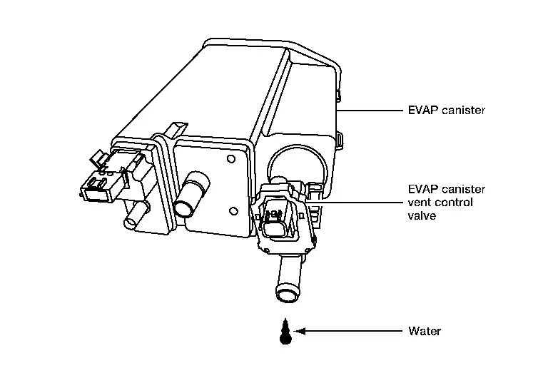
Check connectors for water.
Water should not exist.
Is the inspection result normal?
YES>>
GO TO 10.
NO>>
Replace EVAP control system pressure sensor. Refer to Removal and Installation.
CHECK EVAP CONTROL SYSTEM PRESSURE SENSOR FUNCTION
Refer to DTC Description for DTC P0452, DTC Description for DTC P0453.
Is the inspection result normal?
YES>>
GO TO 11.
NO>>
Replace EVAP control system pressure sensor. Refer to Removal and Installation.
CHECK RUBBER TUBE FOR CLOGGING
-
Disconnect rubber tube connected to EVAP canister vent control valve.
-
Check the rubber tube for clogging.
Is the inspection result normal?
YES>>
GO TO 12.
NO>>
Clean the rubber tube using an air blower.
CHECK EVAP CANISTER VENT CONTROL VALVE
Refer to Component Inspection.
Is the inspection result normal?
YES>>
GO TO 13.
NO>>
Replace EVAP canister vent control valve. Refer to Removal and Installation.
CHECK EVAP PURGE LINE
Inspect EVAP purge line (pipe and rubber tube). Check for evidence of leaks.
Refer to System Description.
Is the inspection result normal?
YES>>
GO TO 14.
NO>>
Replace it.
CLEAN EVAP PURGE LINE
Clean EVAP purge line (pipe and rubber tube) using air blower.
>>
INSPECTION END
P0443 Evap Canister Purge Volume Control Solenoid Valve Nissan Pathfinder
DTC Description
DTC DETECTION LOGIC
| DTC |
CONSULT screen terms (Trouble diagnosis content) |
DTC detection condition | ||
| P0443 | 00 |
PURG VOLUME CONT/V (Evaporative emission system purge control valve circuit) |
Diagnosis condition | — |
| Signal (terminal) | — | |||
| Threshold | The canister purge flow is detected during the specified driving conditions, even when EVAP canister purge volume control solenoid valve is completely closed | |||
| Diagnosis delay time | — | |||
POSSIBLE CAUSE
-
EVAP control system pressure sensor
-
EVAP canister purge volume control solenoid valve (The valve is stuck open.)
-
EVAP canister vent control valve
-
EVAP canister
-
Hoses (Hoses are connected incorrectly or clogged.)
FAIL-SAFE
Not applicable
DTC Confirmation Procedure
PRECONDITIONING
If DTC Confirmation Procedure has been previously conducted, always perform the following procedure before conducting the next test.
-
Turn ignition switch OFF and wait at least 10 seconds.
-
Turn ignition switch ON.
-
Turn ignition switch OFF and wait at least 10 seconds.
TESTING CONDITION:
Always perform test at a temperature of 5°C (41°F) or more.
Do you have CONSULT
YES>>GO TO 2.
NO>>GO TO 3.
PERFORM DTC CONFIRMATION PROCEDURE
 With CONSULT
-
Start engine and warm it up to normal operating temperature.
-
Turn ignition switch OFF and wait at least 10 seconds.
-
Turn ignition switch ON.
-
Turn ignition switch OFF and wait at least 10 seconds.
-
Turn ignition switch ON.
-
On CONSULT screen, select “ENGINE”>>“DTC Work Support”>>“EVAPORATIVE SYSTEM”>>“PURG VOL CN/V P1444”.
-
Touch “START”.
-
Start engine and let it idle until “TESTING” on CONSULT changes to “COMPLETED”. (It will take approximately 10 seconds.)
If “TESTING” is not displayed after 5 minutes, retry from step 2.
-
Touch “SELF-DIAG RESULTS”.
Is “OK” displayed on CONSULT screen?
YES-1>>To check malfunction symptom before repair: Refer to Intermittent Incident.
YES-2>>Confirmation after repair: INSPECTION END
NO>>Proceed to Diagnosis Procedure.
PERFORM DTC CONFIRMATION PROCEDURE
 With GST
-
Start engine and warm it up to normal operating temperature.
-
Turn ignition switch OFF and wait at least 10 seconds.
-
Turn ignition switch ON.
-
Turn ignition switch OFF and wait at least 10 seconds.
-
Start engine and let it idle for at least 20 seconds.
-
Check 1st trip DTC.
Is DTC P0443 displayed?
YES>>Proceed to Diagnosis Procedure.
NO-1>>To check malfunction symptom before repair: Refer to Intermittent Incident.
NO-2>>Confirmation after repair: INSPECTION END
Diagnosis Procedure
CHECK EVAP CANISTER PURGE VOLUME CONTROL SOLENOID VALVE POWER SUPPLY
-
Turn ignition switch OFF.
-
Disconnect EVAP canister purge volume control solenoid valve harness connector.
-
Turn ignition switch ON.
-
Check the voltage between EVAP canister purge volume control solenoid valve harness connector and ground.
+ − Voltage EVAP canister purge volume control solenoid valve Connector Terminal F16 2 Ground Battery voltage
Is the inspection result normal?
YES>>GO TO 3.
NO>>GO TO 2.
CHECK EVAP CANISTER PURGE VOLUME CONTROL SOLENOID VALVE POWER SUPPLY CIRCUIT
-
Turn ignition switch OFF.
-
Disconnect IPDM E/R harness connector.
-
Check the continuity between EVAP canister purge volume control solenoid valve harness connector and IPDM E/R harness connector.
EVAP canister purge volume control solenoid valve IPDM E/R Continuity Connector Terminal Connector Terminal F16 2 F24 73 Existed -
Also check harness for short to power and short to ground.
Is the inspection result normal?
YES>>Perform the trouble diagnosis for power supply circuit.
NO>>Repair or replace error-detected parts.
CHECK EVAP CANISTER PURGE VOLUME CONTROL SOLENOID VALVE OUTPUT SIGNAL CIRCUIT
-
Turn ignition switch OFF.
-
Disconnect ECM harness connector.
-
Check the continuity between EVAP canister purge volume control solenoid valve harness connector and ECM harness connector.
EVAP canister purge volume control solenoid valve ECM Continuity Connector Terminal Connector Terminal F16 1 F79 152 Existed -
Also check harness for short to power and short to ground.
Is the inspection result normal?
YES>>GO TO 4.
NO>>Repair open circuit, short to ground or short to power in harness or connectors.
CHECK EVAP CONTROL SYSTEM PRESSURE SENSOR CONNECTOR
-
Disconnect EVAP control system pressure sensor harness connector.
-
Check connectors for water.
Water should not exist.
Is the inspection result normal?
YES>>GO TO 5.
NO>>Replace EVAP control system pressure sensor. Refer to Removal and Installation.
CHECK EVAP CONTROL SYSTEM PRESSURE SENSOR
Refer to Component Inspection.
Is the inspection result normal?
YES-1>>With CONSULT: GO TO 6.
YES-2>>Without CONSULT: GO TO 7.
NO>>Replace EVAP control system pressure sensor. Refer to Removal and Installation.
CHECK EVAP CANISTER PURGE VOLUME CONTROL SOLENOID VALVE
 With CONSULT
-
Turn ignition switch OFF.
-
Reconnect harness connectors disconnected.
-
Start the engine.
-
On CONSULT screen, select “ENGINE”>>“Active Test”>>“PURG VOL CONT/V”.
-
Check that engine speed varies according to the valve opening.
Does engine speed vary according to the valve opening?
YES>>GO TO 8.
NO>>GO TO 7.
CHECK EVAP CANISTER PURGE VOLUME CONTROL SOLENOID VALVE
Refer to Component Inspection.
Is the inspection result normal?
YES>>GO TO 8.
NO>>Replace EVAP canister purge volume control solenoid valve. Refer to Component Parts Location.
CHECK RUBBER TUBE FOR CLOGGING
-
Disconnect rubber tube connected to EVAP canister vent control valve.
-
Check the rubber tube for clogging.
Is the inspection result normal?
YES>>GO TO 9.
NO>>Clean the rubber tube using an air blower.
CHECK EVAP CANISTER VENT CONTROL VALVE
Refer to Component Inspection.
Is the inspection result normal?
YES>>GO TO 10.
NO>>Replace EVAP canister vent control valve. Refer to Removal and Installation.
CHECK IF EVAP CANISTER IS SATURATED WITH WATER
-
Remove EVAP canister with EVAP canister vent control valve and EVAP control system pressure sensor attached.
-
Check if water will drain from EVAP canister.

Does water drain from the EVAP canister?
YES>>GO TO 11.
NO>>INSPECTION END
CHECK EVAP CANISTER
Weigh the EVAP canister with the EVAP canister vent control valve and EVAP control system pressure sensor attached.
The weight should be less than 2.1 kg (4.6 lb).
Is the inspection result normal?
YES>>INSPECTION END
NO>>GO TO 12.
DETECT MALFUNCTIONING PART
Check the following.
-
EVAP canister for damage
-
EVAP hose between EVAP canister and Nissan Pathfinder vehicle frame for clogging or poor connection
>>
Repair hose or replace EVAP canister.
Component Inspection
CHECK EVAP CANISTER PURGE VOLUME CONTROL SOLENOID VALVE
 With CONSULT
-
Turn ignition switch OFF.
-
Reconnect all harness connectors disconnected.
-
Disconnect EVAP purge hoses connected to EVAP canister purge volume control solenoid valve.
-
Start the engine.
-
On CONSULT screen, select “ENGINE”>>“Active Test”>>“PURG VOL CONT/V”.
-
Touch “Qd” and “Qu” on CONSULT screen to adjust “PURG VOL C/V” opening and check air passage continuity of EVAP canister purge volume control solenoid valve under the following conditions.

|
Condition (PURG VOL C/V value) |
Air passage continuity between and and
 |
|---|---|
| 100% | Existed |
| 0% | Not existed |
 Without CONSULT
-
Turn ignition switch OFF.
-
Disconnect EVAP canister purge volume control solenoid valve harness connector.
-
Disconnect EVAP purge hoses connected to EVAP canister purge volume control solenoid valve.
-
Check air passage continuity of EVAP canister purge volume control solenoid valve under the following conditions.
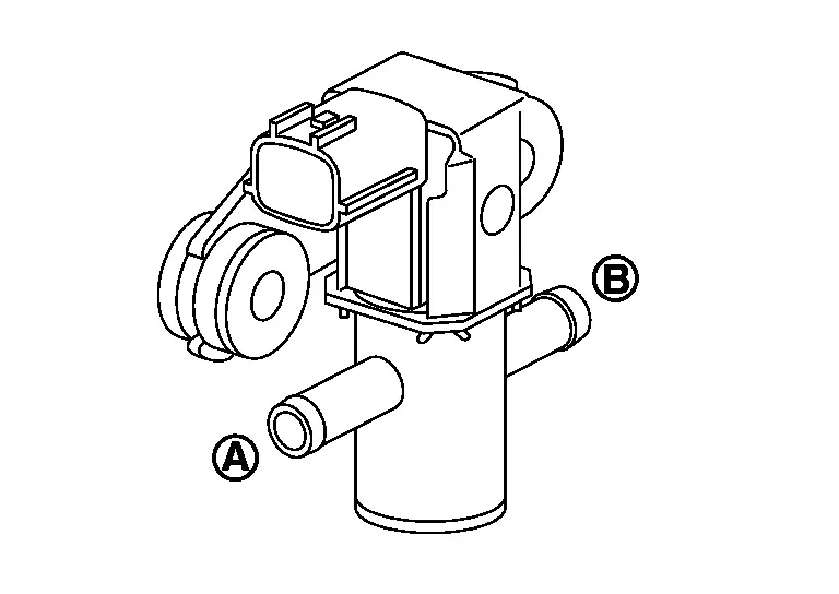
Condition Air passage continuity
between and
and

12V direct current supply between terminals 1 and 2 Existed No supply Not existed
Is the inspection result normal?
YES>>INSPECTION END
NO>>Replace EVAP canister purge volume control solenoid valve. Refer to Component Parts Location.
P0447 Evap Canister Vent Control Valve Nissan Pathfinder SUV
DTC Description
DTC DETECTION LOGIC
| DTC |
CONSULT screen terms (Trouble diagnosis content) |
DTC detection condition | ||
| P0447 | 00 |
VENT CONTROL VALVE (Evaporative emission system vent control circuit open) |
Diagnosis condition | Engine running at idle |
| Signal (terminal) | EVAP canister vent control valve signal | |||
| Threshold | An improper voltage signal is sent to ECM through EVAP canister vent control valve | |||
| Diagnosis delay time | — | |||
POSSIBLE CAUSE
-
Harness or connectors (EVAP canister vent control valve circuit is open or shorted.)
-
EVAP canister vent control valve
FAIL-SAFE
Not applicable
DTC Confirmation Procedure
PRECONDITIONING
If DTC Confirmation Procedure has been previously conducted, always perform the following procedure before conducting the next test.
-
Turn ignition switch OFF and wait at least 10 seconds.
-
Turn ignition switch ON.
-
Turn ignition switch OFF and wait at least 10 seconds.
TESTING CONDITION:
Before performing the following procedure, confirm battery voltage is more than 11 V at idle.
>>
GO TO 2.
PERFORM DTC CONFIRMATION PROCEDURE
-
Start engine and wait at least 8 seconds.
-
Check 1st trip DTC.
Is DTC P0447 detected?
YES>>Proceed to Diagnosis Procedure.
NO-1>>To check malfunction symptom before repair: Refer to Intermittent Incident.
NO-2>>Confirmation after repair: INSPECTION END
Diagnosis Procedure
INSPECTION START
Do you have CONSULT?
YES>>GO TO 2.
NO>>GO TO 3.
CHECK EVAP CANISTER VENT CONTROL VALVE CIRCUIT
 With CONSULT
-
Turn ignition switch OFF and then ON.
-
On CONSULT screen, select “ENGINE”>>“Active Test”>>“VENT CONTROL/V”.
-
Touch “ON/OFF” on CONSULT screen.
-
Check for operating sound of the valve.
Clicking sound should be heard.
Is the inspection result normal?
YES>>GO TO 6.
NO>>GO TO 3.
CHECK EVAP CANISTER VENT CONTROL VALVE POWER SUPPLY
-
Turn ignition switch OFF.
-
Disconnect EVAP canister vent control valve harness connector.
-
Turn ignition switch ON.
-
Check the voltage between EVAP canister vent control valve harness connector and ground.
+ − Voltage EVAP canister vent control valve Connector Terminal B31 1 Ground Battery voltage
Is the inspection result normal?
YES>>GO TO 5.
NO>>GO TO 4.
CHECK EVAP CANISTER VENT CONTROL VALVE POWER SUPPLY CIRCUIT
-
Turn ignition switch OFF.
-
Disconnect IPDM E/R harness connector.
-
Check the continuity between EVAP canister vent control valve harness connector and IPDM E/R harness connector.
EVAP canister vent control valve IPDM E/R Continuity Connector Terminal Connector Terminal B31 1 F24 78 Existed -
Also check harness for short to ground.
Is the inspection result normal?
YES>>Perform the trouble diagnosis for power supply circuit.
NO>>Repair or replace error-detected parts.
CHECK EVAP CANISTER VENT CONTROL VALVE OUTPUT SIGNAL CIRCUIT
-
Turn ignition switch OFF.
-
Disconnect ECM harness connector.
-
Check the continuity between EVAP canister vent control valve harness connector and ECM harness connector.
EVAP canister vent control valve ECM Continuity Connector Terminal Connector Terminal B31 2 E32 193 Existed -
Also check harness for short to power and short to ground.
Is the inspection result normal?
YES>>GO TO 6.
NO>>Repair or replace error-detected parts.
CHECK RUBBER TUBE FOR CLOGGING
-
Disconnect rubber tube connected to EVAP canister vent control valve.
-
Check the rubber tube for clogging.
Is the inspection result normal?
YES>>GO TO 7.
NO>>Clean the rubber tube using an air blower.
CHECK EVAP CANISTER VENT CONTROL VALVE
Refer to Component Inspection.
Is the inspection result normal?
YES>>INSPECTION END
NO>>Replace EVAP canister vent control valve. Refer to Removal and Installation.
Component Inspection
CHECK EVAP CANISTER VENT CONTROL VALVE-I
-
Turn ignition switch OFF.
-
Remove EVAP canister vent control valve from EVAP canister. Refer to Removal and Installation.
-
Check portion
 of EVAP canister vent control valve for rust.
Is it rusted?
YES>>Replace EVAP canister vent control valve. Refer to Removal and Installation.
NO>>GO TO 2.
CHECK EVAP CANISTER VENT CONTROL VALVE-II
 With CONSULT
-
Reconnect harness connectors disconnected.
-
Turn ignition switch ON.
-
On CONSULT screen, select “ENGINE”>>“Active Test”>>“VENT CONTROL/V”.
-
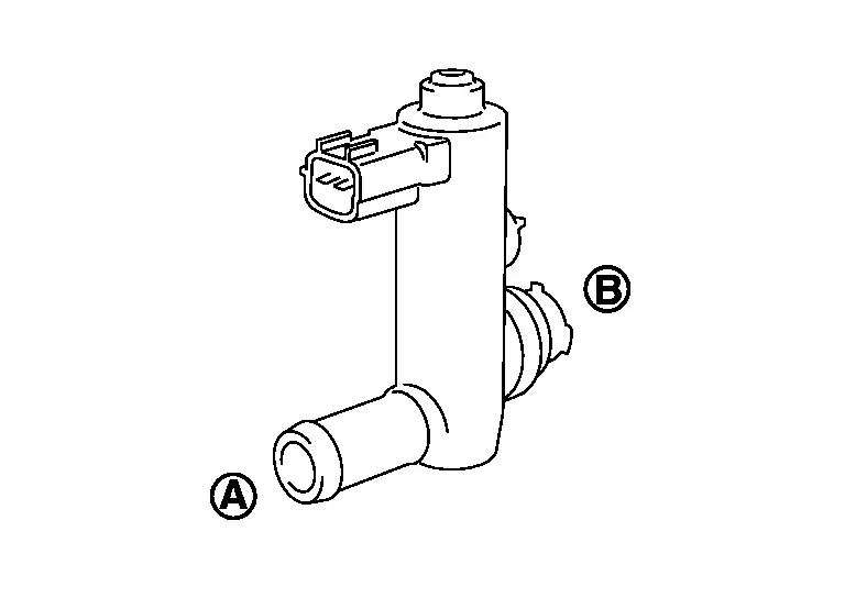
Check air passage continuity and operation delay time.

Make sure that new O-ring is installed properly.
Condition VENT CONT/V Air passage continuity between  and
and

ON Not existed OFF Existed Operation takes less than 1 second.
 Without CONSULT
-
Disconnect EVAP canister vent control valve harness connector.
-
Check air passage continuity and operation delay time under the following conditions.

Make sure that new O-ring is installed properly.
Condition Air passage continuity between  and
and

12 V direct current supply between terminals 1 and 2 Not existed OFF Existed Operation takes less than 1 second.
Is the inspection result normal?
YES>>GO TO 3.
NO>>Replace EVAP canister vent control valve. Refer to Removal and Installation.
CHECK EVAP CANISTER VENT CONTROL VALVE-III
 With CONSULT
-
Clean the air passage [portion
 to
to
 ] of EVAP canister vent control valve using an air blower.
 -
On CONSULT screen, select “ENGINE”>>“Active Test”>>“VENT CONTROL/V”.
-
Check air passage continuity and operation delay time.

Make sure that new O-ring is installed properly.
Condition VENT CONT/V Air passage continuity between  and
and

ON Not existed OFF Existed Operation takes less than 1 second.
 Without CONSULT
-
Clean the air passage [portion
 to
to
 ] of EVAP canister vent control valve using an air blower.
 -
Check air passage continuity and operation delay time under the following conditions.
Make sure that new O-ring is installed properly.
Condition Air passage continuity between  and
and

12 V direct current supply between terminals 1 and 2 Not existed OFF Existed Operation takes less than 1 second.
Is the inspection result normal?
YES>>INSPECTION END
NO>>Replace EVAP canister vent control valve. Refer to Removal and Installation.
P0450 Evap Control System Pressure Sensor Nissan Pathfinder 2026
DTC Description
DTC DETECTION LOGIC
| DTC |
CONSULT screen terms (Trouble diagnosis content) |
DTC detection condition | ||
| P0450 | 00 |
EVAP SYS PRES SEN (EVAP System Pressure Sensor/Switch "A" Circuit) |
Diagnosis condition | — |
| Signal (terminal) | EVAP control system pressure sensor signal | |||
| Threshold | An excessively low or high voltage from the sensor is sent to ECM | |||
| Diagnosis delay time | — | |||
POSSIBLE CAUSE
-
Harness or connectors (EVAP control system pressure sensor circuit is shorted.)
-
EVAP control system pressure sensor
FAIL-SAFE
Not applicable
DTC Confirmation Procedure
PRECONDITIONING
If DTC Confirmation Procedure has been previously conducted, always perform the following procedure before conducting the next test.
-
Turn ignition switch OFF and wait at least 10 seconds.
-
Turn ignition switch ON.
-
Turn ignition switch OFF and wait at least 10 seconds.
TESTING CONDITION:
Always perform test at a temperature of 5°C (41°F) or more.
>>
GO TO 2.
PERFORM DTC CONFIRMATION PROCEDURE
 With CONSULT
-
Start engine and warm it up to normal operating temperature.
-
Turn ignition switch OFF and wait at least 10 seconds.
-
Turn ignition switch ON.
-
Select “DATA MONITOR” mode of “ENGINE” using CONSULT.
-
Make sure that “FUEL T/TMP SE” indication is more than 0°C (32°F).
-
Start engine and wait at least 20 seconds.
-
Check 1st trip DTC.
 With GST
-
Start engine and warm it up to normal operating temperature.
-
Set voltmeter probes to ECM harness connector terminals as per the following.
ECM Voltage Connector + − Terminal E32 180 204 Less than 4.2 V -
Make sure that the voltage is less than 4.2 V.
-
Turn ignition switch OFF and wait at least 10 seconds.
-
Start engine and wait at least 20 seconds.
-
Check 1st trip DTC.
Is 1st trip DTC detected?
YES>>
Proceed to DTC Diagnosis Procedure.
NO-1>>
To check malfunction symptom before repair: Refer to Intermittent Incident.
NO-2>>
Confirmation after repair: INSPECTION END
DTC Diagnosis Procedure
CHECK EVAP CONTROL SYSTEM PRESSURE SENSOR CONNECTOR FOR WATER
-
Turn ignition switch OFF.
-
Disconnect EVAP control system pressure sensor harness connector.
-
Check sensor harness connector for water.
Water should not exist.
Is the inspection result normal?
YES>>
GO TO 2.
NO>>
Repair or replace harness connector.
CHECK EVAP CONTROL SYSTEM PRESSURE SENSOR POWER SUPPLY
-
Turn ignition switch ON.
-
Check the voltage between EVAP control system pressure sensor harness connector and ground.
+ − Voltage
(Approx.)EVAP control system pressure sensor Connector Terminal B36 3 Ground 5 V
Is the inspection result normal?
YES>>
GO TO 4.
NO>>
GO TO 3.
CHECK EVAP CONTROL SYSTEM PRESSURE SENSOR POWER SUPPLY CIRCUIT
-
Turn ignition switch OFF.
-
Disconnect ECM harness connector.
-
Check the continuity between EVAP control system pressure sensor harness connector and ECM harness connector.
+ − Continuity EVAP control system pressure sensor ECM Connector Terminal Connector Terminal B36 3 E32 177 Existed -
Also check harness for short to ground and to power.
Is the inspection result normal?
YES>>
Perform the trouble diagnosis for power supply circuit.
NO>>
Repair or replace error-detected parts
CHECK EVAP CONTROL SYSTEM PRESSURE SENSOR GROUND CIRCUIT
-
Turn ignition switch OFF.
-
Disconnect ECM harness connector.
-
Check the continuity between EVAP control system pressure sensor harness connector and ECM harness connector.
+ − Continuity EVAP control system pressure sensor ECM Connector Terminal Connector Terminal B36 1 E32 200 Existed -
Also check harness for short to power.
Is the inspection result normal?
YES>>
GO TO 5.
NO>>
Repair or replace error-detected parts.
CHECK EVAP CONTROL SYSTEM PRESSURE SENSOR SIGNAL CIRCUIT
-
Check the continuity between EVAP control system pressure sensor harness connector and ECM harness connector.
+ − Continuity EVAP control system pressure sensor ECM Connector Terminal Connector Terminal B36 2 E32 173 Existed -
Also check harness for short to ground and to power.
Is the inspection result normal?
YES>>
GO TO 6.
NO>>
Repair or replace error-detected parts.
CHECK RUBBER TUBE
-
Disconnect rubber tube connected to EVAP canister vent control valve.
-
Check the rubber tube for clogging.
Is the inspection result normal?
YES>>
GO TO 7.
NO>>
Clean the rubber tube using an air blower, repair or replace rubber tube.
CHECK EVAP CANISTER VENT CONTROL VALVE
Refer to Component Inspection.
Is the inspection result normal?
YES>>
GO TO 8.
NO>>
Replace EVAP canister vent control valve. Refer to Removal and Installation.
CHECK IF EVAP CANISTER IS SATURATED WITH WATER
-
Remove EVAP canister with EVAP canister vent control valve and EVAP control system pressure sensor attached.
-
Check if water will drain from the EVAP canister.
Does water drain from EVAP canister?
YES>>
GO TO 9.
NO>>
Check intermittent incident. Refer to Intermittent Incident.
CHECK EVAP CANISTER
Weigh the EVAP canister with the EVAP canister vent control valve and EVAP control system pressure sensor attached.
The weight should be less than 2.1 kg (4.6 lb).
Is the inspection result normal?
YES>>
Check intermittent incident. Refer to Intermittent Incident.
NO>>
GO TO 10.
DETECT MALFUNCTIONING PART
Check the following.
-
EVAP canister for damage
-
EVAP hose between EVAP canister and Nissan Pathfinder vehicle frame for clogging or poor connection
Is the inspection result normal?
YES>>
Replace EVAP control system pressure sensor. Refer to Removal and Installation.
NO>>
Repair hose or replace EVAP canister. Refer to Removal and Installation.
Component Inspection
CHECK EVAP CANISTER VENT CONTROL VALVE-I
-
Turn ignition switch OFF.
-
Remove EVAP canister vent control valve from EVAP canister. Refer to Removal and Installation.
-
Check portion
 of EVAP canister vent control valve for rust.
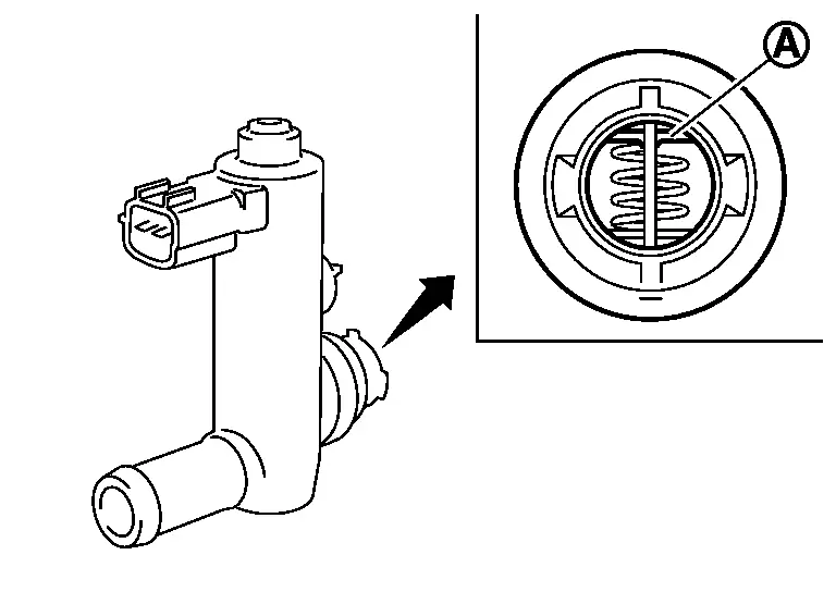
Is it rusted?
YES>>
Replace EVAP canister vent control valve. Refer to Removal and Installation.
NO>>
GO TO 2.
CHECK EVAP CANISTER VENT CONTROL VALVE-II
 With CONSULT
-
Reconnect harness connectors disconnected.
-
Turn ignition switch ON.
-
On CONSULT screen, select “ENGINE”>>“Active Test”>>“VENT CONTROL/V”.
-
Check air passage continuity and operation delay time.

Make sure that new O-ring is installed properly.
Condition VENT CONT/V Air passage continuity between  and
and 
ON Not existed OFF Existed Operation takes less than 1 second.
 Without CONSULT
-
Disconnect EVAP canister vent control valve harness connector.
-
Check air passage continuity and operation delay time under the following conditions.

Make sure that new O-ring is installed properly.
Condition Air passage continuity between  and
and 
12 V direct current supply between terminals 1 and 2 Not existed OFF Existed Operation takes less than 1 second.
Is the inspection result normal?
YES>>
GO TO 3.
NO>>
Replace EVAP canister vent control valve. Refer to Removal and Installation.
CHECK EVAP CANISTER VENT CONTROL VALVE-III
 With CONSULT
-
Clean the air passage [portion
 to
to  ] of EVAP canister vent control valve using an air blower.
 -
On CONSULT screen, select “ENGINE”>>“Active Test”>>“VENT CONTROL/V”.
-
Check air passage continuity and operation delay time.

Make sure that new O-ring is installed properly.
Condition VENT CONT/V Air passage continuity between  and
and 
ON Not existed OFF Existed Operation takes less than 1 second.
 Without CONSULT
-
Clean the air passage [portion
 to
to  ] of EVAP canister vent control valve using an air blower.
 -
Check air passage continuity and operation delay time under the following conditions.

Make sure that new O-ring is installed properly.
Condition Air passage continuity between  and
and 
12 V direct current supply between terminals 1 and 2 Not existed OFF Existed Operation takes less than 1 second.
Is the inspection result normal?
YES>>
INSPECTION END
NO>>
Replace EVAP canister vent control valve. Refer to Removal and Installation.
P0461 Fuel Level Sensor Nissan Pathfinder SUV
DTC Description
Driving long distances naturally affect fuel gauge level.
This diagnosis detects the fuel gauge malfunction of the gauge not moving even after a long distance has been driven.
DTC DETECTION LOGIC
| DTC |
CONSULT screen terms (Trouble diagnosis content) |
DTC detection condition | ||
| P0461 | 00 |
FUEL LEVEL SENSOR (Fuel level sensor “A” circuit range/performance) |
Diagnosis condition | — |
| Signal (terminal) | Fuel level sensor signal | |||
| Threshold | The output signal of the fuel level sensor does not change within the specified range even though the Nissan Pathfinder vehicle has been driven a long distance | |||
| Diagnosis delay time | — | |||
POSSIBLE CAUSE
-
Harness or connectors (CAN communication line is open or shorted)
-
Harness or connectors (Fuel level sensor circuit is open or shorted)
-
Combination meter
-
Fuel level sensor
FAIL-SAFE
Not applicable
DTC Confirmation Procedure
CHECK DTC PRIORITY
If DTC P0461 is displayed with DTC UXXXX or P0607, first perform the confirmation procedure (trouble diagnosis) for DTC UXXXX or P0607.
Is DTC UXXXX or P0607 detected?
YES>>Perform diagnosis of applicable.
-
DTC UXXXX: Refer to DTC Index.
-
DTC P0607: Refer to DTC Description.
GO TO 2.
PRECONDITIONING
WARNING:
When performing the following procedure, always observe the handling of the fuel. Refer to General Precautions.
TESTING CONDITION:
Before starting component function check, preparation of draining fuel and refilling fuel is required.
Do you have CONSULT?
YES>>GO TO 3.
NO>>GO TO 4.
PERFORM COMPONENT FUNCTION CHECK
 NOTE:
NOTE:
Use component function check to check the overall function of the fuel level sensor. During this check, a 1st trip DTC might not be confirmed.
 With CONSULT
 NOTE:
NOTE:
Start from step 10, if it is possible to confirm that the fuel cannot be drained by 30
 (7-7/8 US gal, 6-5/8 Imp gal) in advance.
-
Prepare a fuel container and a spare hose.
-
Release fuel pressure from fuel line, refer to Work Procedure.
-
Remove the fuel feed hose on the fuel level sensor unit.
-
Connect a spare fuel hose where the fuel feed hose was removed.
-
Turn ignition switch OFF and wait at least 10 seconds then turn ON.
-
On CONSULT screen, select “ENGINE”>>“Data Monitor”>>“FUEL LEVEL SE”.
-
Check “FUEL LEVEL SE” output voltage and note it.
-
On CONSULT screen, select “ENGINE”>>“Active Test”>>“FUEL PUMP RELAY”.
-
Touch “ON” and drain fuel approximately 30
 (7-7/8 US gal, 6-5/8 Imp gal) and stop it.
 -
Check “FUEL LEVEL SE” output voltage and note it.
-
Fill fuel into the fuel tank for 30
 (7-7/8 US gal, 6-5/8 Imp gal).
 -
Check “FUEL LEVEL SE” output voltage and note it.
-
Confirm whether the voltage changes more than 0.03V during step 7 to 10 and 10 to 12.
Is the inspection result normal?
YES-1>>To check malfunction symptom before repair: Refer to Intermittent Incident.
YES-2>>Confirmation after repair: INSPECTION END
NO>>Proceed to Diagnosis Procedure.
PERFORM COMPONENT FUNCTION CHECK
 Without CONSULT
 NOTE:
NOTE:
Start from step 8, if it is possible to confirm that the fuel cannot be drained by 30
 (7-7/8 US gal, 6-5/8 Imp gal) in advance.
-
Prepare a fuel container and a spare hose.
-
Release fuel pressure from fuel line. Refer to Work Procedure.
-
Remove the fuel feed hose on the fuel level sensor unit.
-
Connect a spare fuel hose where the fuel feed hose was removed.
-
Turn ignition switch ON.
-
Drain fuel by 30
 (7-7/8 US gal, 6-5/8 Imp gal) from the fuel tank using proper equipment.
 -
Confirm that the fuel gauge indication varies.
-
Fill fuel into the fuel tank for 30
 (7-7/8 US gal, 6-5/8 Imp gal).
 -
Confirm that the fuel gauge indication varies.
Is the inspection result normal?
YES-1>>To check malfunction symptom before repair: Refer to Intermittent Incident.
YES-2>>Confirmation after repair: INSPECTION END
NO>>Proceed to Diagnosis Procedure.
Diagnosis Procedure
CHECK DTC PRIORITY
If DTC P0461 is displayed with DTC UXXXX or P0607, first perform the confirmation procedure (trouble diagnosis) for DTC UXXXX or P0607.
Is DTC UXXXX or P0607 detected?
YES>>Perform diagnosis of applicable.
-
DTC UXXXX: Refer to DTC Index.
-
DTC P0607: Refer to DTC Description.
GO TO 2.
CHECK DTC WITH COMBINATION METER
Check DTC with combination meter.
-
FULL TFT METER: Refer to CONSULT Function (METER/M&A).
-
7 INCH INFORMATION DISPLAY: Refer to CONSULT Function (METER/M&A).
Is the inspection result normal?
YES>>INSPECTION END
NO>>Proceed to component function check.
-
FULL TFT METER: Refer to DiagnosisProcedure.
-
7 INCH INFORMATION DISPLAY: Refer to DiagnosisProcedure.
P0500 Vss Nissan Pathfinder 2026
DTC Description
ECM receives vehicle speed signals from two different paths via CAN communication line: One is from the ABS actuator and electric unit (control unit) via the combination unit and the other is from TCM.
DTC DETECTION LOGIC
| DTC |
CONSULT screen terms (Trouble diagnosis content) |
DTC detection condition | ||
| P0500 | 00 |
Nissan Pathfinder Vehicle SPEED SEN A (Vehicle speed sensor “A”) |
Diagnosis condition |
|
| Signal (terminal) | Nissan Pathfinder Vehicle speed signal | |||
| Threshold | The difference between a Nissan Pathfinder vehicle speed calculated by a output speed sensor transmitted from TCM to ECM via CAN communication and the Nissan Pathfinder vehicle speed indicated on the combination meter exceeds 15 km/h (10 MPH) | |||
| Diagnosis delay time | 5 seconds or more | |||
POSSIBLE CAUSE
-
Harness or connector (CAN communication line is open or shorted.)
-
Combination meter
-
ABS actuator and electric unit (control unit)
-
Wheel sensor
-
TCM
-
Output speed sensor
FAIL-SAFE
| Fail safe mode | Nissan Pathfinder Vehicle behavior | |
|---|---|---|
| Traveling control mode | Accelerator angle variation control |
ECM controls the accelerator pedal depression speed to make it slower than actual speed. This causes a drop in accelerating performance and encourages the driver to repair malfunction.
ECM does not control the accelerator pedal releasing speed. |
| Combustion control mode | Stratified charge combustion control at starting | No stratified charge combustion at starting (cold start). |
| Idle speed control | Stops feedback control of idle speed and controls with specified speed. | |
| Recovery speed control at decelerating | Stops recovery speed control by the fuel cut at decelerating and controls with specified speed. | |
| Idle neutral control | Stops idle neutral control. | |
 NOTE:
NOTE:
DTC Confirmation Procedure
PRECONDITIONING
If DTC Confirmation Procedure has been previously conducted, always perform the following procedure before conducting the next test.
-
Turn ignition switch OFF and wait at least 10 seconds.
-
Turn ignition switch ON.
-
Turn ignition switch OFF and wait at least 10 seconds.
>>
GO TO 2.
PERFORM DTC CONFIRMATION PROCEDURE
-
Start engine.
-
Shift the selector lever to D range and wait at least for 2 seconds.
-
Drive the Nissan Pathfinder vehicle at least 5 seconds at 20 km/h (13 MPH) or more.
CAUTION:
Always drive vehicle at a safe speed.
 NOTE:
NOTE:
This procedure may be conducted with the drive wheels lifted in the shop or by driving the Nissan Pathfinder vehicle. If a road test is expected to be easier, it is unnecessary to lift the vehicle.
-
Check 1st trip DTC.
Is DTC P0500 detected?
YES>>Proceed to Diagnosis Procedure.
NO-1>>To check malfunction symptom before repair: Refer to Intermittent Incident.
NO-2>>Confirmation after repair: INSPECTION END
Diagnosis Procedure
CHECK DTC WITH TCM
Check DTC with TCM. Refer to CONSULT Function.
Is the inspection result normal?
YES>>GO TO 2.
NO>>Perform trouble shooting relevant to DTC indicated.
CHECK DTC WITH ABS ACTUATOR AND ELECTRIC UNIT (CONTROL UNIT)
Check DTC with ABS actuator and electric unit (control unit). Refer to CONSULT Function.
Is the inspection result normal?
YES>>GO TO 3.
NO>>Perform trouble shooting relevant to DTC indicated.
CHECK DTC WITH COMBINATION METER
Check DTC with combination meter.
-
FULL TFT METER: Refer to CONSULT Function (METER/M&A).
-
7 INCH INFORMATION DISPLAY: Refer to CONSULT Function (METER/M&A).
Is the inspection result normal?
YES>>GO TO 4.
NO>>Perform trouble shooting relevant to DTC indicated.
CHECK OUTPUT SPEED SENSOR
Check output speed sensor. Refer to Diagnosis Procedure.
Is the inspection result normal?
YES>>GO TO 5.
NO>>Replace or replace error-detected parts.
CHECK WHEEL SENSOR
Check wheel sensor. Refer to Diagnosis Procedure.
Is the inspection result normal?
YES>>INSPECTION END
NO>>Replace or replace error-detected parts.
P0506 Isc System Nissan Pathfinder SUV
DTC Description
The ECM controls the engine idle speed to a specified level through the fine adjustment of the air, which is let into the intake manifold, by operating the electric throttle control actuator. The operating of the throttle valve is varied to allow for optimum control of the engine idling speed. The crankshaft position sensor 1 (POS) detects the actual engine speed and sends a signal to the ECM.
The ECM controls the electric throttle control actuator so that the engine speed coincides with the target value memorized in the ECM. The target engine speed is the lowest speed at which the engine can operate steadily. The optimum value stored in the ECM is determined by taking into consideration various engine conditions, such as during warming up, deceleration and engine load (air conditioner, power steering and cooling fan operation, etc.).
DTC DETECTION LOGIC
| DTC |
CONSULT screen terms (Trouble diagnosis content) |
DTC detection condition | ||
| P0506 | 00 |
ISC SYSTEM (Idle air control system RPM lower than expected) |
Diagnosis condition | — |
| Signal (terminal) | — | |||
| Threshold | The idle speed is less than the target idle speed by 100 rpm or more | |||
| Diagnosis delay time | — | |||
POSSIBLE CAUSE
-
Electric throttle control actuator
-
Intake air leak
FAIL-SAFE
Not applicable
DTC Confirmation Procedure
CHECK DTC PRIORITY
If DTC P0506 is displayed with other DTC, first perform the confirmation procedure (trouble diagnosis) for other DTC.
Is applicable DTC detected?
YES>>Perform diagnosis of applicable. Refer to DTC Index.
NO>>GO TO 2.
PRECONDITIONING
If DTC Confirmation Procedure has been previously conducted, always perform the following procedure before conducting the next test.
-
Turn ignition switch OFF and wait at least 10 seconds.
-
Turn ignition switch ON.
-
Turn ignition switch OFF and wait at least 10 seconds.
If the idle speed is out of the specified value, perform Description, before conducting DTC Confirmation Procedure.
TESTING CONDITION:
-
Before performing the following procedure, confirm that battery voltage is more than 11 V at idle.
-
Always perform the test at a temperature above −10°C(14°F).
>>
GO TO 3.
PERFORM DTC CONFIRMATION PROCEDURE
-
Start engine and warm it up to normal operating temperature.
-
Turn ignition switch OFF and wait at least 10 seconds.
-
Turn ignition switch ON.
-
Turn ignition switch OFF and wait at least 10 seconds.
-
Restart engine and run it for at least 1 minute at idle speed.
-
Check 1st trip DTC.
Is DTC P0506 detected?
YES>>Proceed to Diagnosis Procedure.
NO-1>>To check malfunction symptom before repair: Refer to Intermittent Incident.
NO-2>>Confirmation after repair: INSPECTION END
Diagnosis Procedure
CHECK DTC PRIORITY
If DTC P0506 is displayed with other DTC, first perform the confirmation procedure (trouble diagnosis) for other DTC.
Is applicable DTC detected?
YES>>Perform diagnosis of applicable. Refer to DTC Index.
NO>>GO TO 2.
CHECK INTAKE AIR LEAK
-
Start engine and let it idle.
-
Listen for an intake air leak after the mass air flow sensor.
Is intake air leak detected?
YES>>Discover air leak location and repair.
NO>>GO TO 3.
REPLACE ECM
-
Stop the engine.
-
Replace ECM. Refer to Removal and Installation.
-
Proceed to Description.
>>
INSPECTION END
P050a Cold Start Control Nissan Pathfinder SUV
DTC Description
ECM controls ignition timing and engine idle speed when engine is started with pre-warming up condition.
This control promotes the activation of three way catalyst by heating the catalyst and reduces emissions.
DTC DETECTION LOGIC
| DTC |
CONSULT screen terms (Trouble diagnosis content) |
DTC detection condition | ||
| P050A | 00 |
COLD START CONTROL (Cold start idle air control system performance) |
Diagnosis condition | — |
| Signal (terminal) | — | |||
| Threshold | ECM does not control engine idle speed properly when engine is started with pre-warming up condition | |||
| Diagnosis delay time | — | |||
POSSIBLE CAUSE
-
Lack of intake air volume
-
Fuel injection system
-
ECM
FAIL-SAFE
| Fail safe mode | Nissan Pathfinder Vehicle behavior | |
|---|---|---|
| Traveling control mode | Accelerator angle variation control |
ECM controls the accelerator pedal depression speed to make it slower than actual speed. This causes a drop in accelerating performance and encourages the driver to repair malfunction.
ECM does not control the accelerator pedal releasing speed. |
| Combustion control mode | Stratified charge combustion control at starting | No stratified charge combustion at starting (cold start). |
 NOTE:
NOTE:
DTC Confirmation Procedure
CHECK DTC PRIORITY
If DTC P050A is displayed with other DTC, first perform the confirmation procedure (trouble diagnosis) for other DTC.
Is applicable DTC detected?
YES>>Perform diagnosis of applicable. Refer to DTC Index.
NO>>GO TO 2.
PRECONDITIONING
If DTC Confirmation Procedure has been previously conducted, always perform the following procedure before conducting the next test.
-
Turn ignition switch OFF and wait at least 10 seconds.
-
Turn ignition switch ON.
-
Turn ignition switch OFF and wait at least 10 seconds.
TESTING CONDITION:
Before performing the following procedure, confirm that battery voltage is more than 11 V at idle.
>>
GO TO 3.
PERFORM DTC CONFIRMATION PROCEDURE-I
 With CONSULT
-
Turn ignition switch OFF and wait at least 10 seconds.
-
Turn ignition switch ON.
-
On CONSULT screen, select “ENGINE”>>“Data Monitor”.
-
Check the indication of “COOLAN TEMP/S”.
 With GST
Follow the procedure “With CONSULT” above.
Is the value of “COOLAN TEMP/S” between 4°C (39°F) and 36°C (97°F)?
YES>>GO TO 4.
NO-1 [If it is below 4°C (39°F)]>>Warm up the engine until the value of “COOLAN TEMP/S” reaches 4°C (39°F) or more. Retry from step 1.
NO-2 [If it is above 36°C (97°F)]>>Cool engine down to less than 36°C (97°F). Retry from step 1.
PERFORM DTC CONFIRMATION PROCEDURE-II
 With CONSULT
-
Set the select lever in N range.
-
Start the engine and warm up in idle with the value of “COOLAN TEMP/S” between 4°C (39°F) and 40°C (104°F) for more than 15 seconds.
-
Check 1st trip DTC.
 With GST
Follow the procedure “With CONSULT” above.
Is DTC P050A detected?
YES>>Proceed to Diagnosis Procedure.
NO-1>>To check malfunction symptom before repair: Refer to Intermittent Incident.
NO-2>>Confirmation after repair: INSPECTION END
Diagnosis Procedure
CHECK DTC PRIORITY
If DTC P050A is displayed with other DTC, first perform the confirmation procedure (trouble diagnosis) for other DTC.
Is applicable DTC detected?
YES>>Perform diagnosis of applicable. Refer to DTC Index.
NO>>GO TO 2.
PERFORM IDLE AIR VOLUME LEARNING
Perform Description.
Is Idle Air Volume Learning carried out successfully?
YES>>GO TO 3.
NO>>Follow the instruction of Idle Air Volume Learning.
CHECK Intake system
Check for the cause of intake air volume lacking. Refer to the following.
-
Crushed intake air passage
-
Intake air passage clogging
-
Clogging of throttle body
Is the inspection result normal?
YES>>GO TO 4.
NO>>Repair or replace malfunctioning part
CHECK FUEL INJECTION SYSTEM FUNCTION
Perform all DTC CONFIRMATION PROCEDURE related for DTC P0171, P0174.
-
For DTC P0171, Refer to DTC Description.
-
For DTC P0174, Refer to DTC Description.
Is the inspection result normal?
YES>>GO TO 5.
NO>>Perform Diagnosis Procedure related for DTC P0171, P0174.
-
For DTC P0171, Refer to Diagnosis Procedure.
-
For DTC P0174, Refer to Diagnosis Procedure.
PERFORM DTC CONFIRMATION PROCEDURE
-
Turn ignition switch ON.
-
Erase DTC.
-
Perform DTC Confirmation Procedure.
See DTC Description.
Is the DTC P050A displayed again?
YES>>GO TO 6.
NO>>INSPECTION END
REPLACE ECM
-
Replace ECM. Refer to Removal and Installation.
-
Proceed to Description.
>>
INSPECTION END
P0520 Eop Sensor Nissan Pathfinder
DTC Description
DTC DETECTION LOGIC
| DTC |
CONSULT screen terms (Trouble diagnosis content) |
DTC detection condition | ||
| P0520 | 00 |
EOP SENSOR/SWITCH [Engine oil pressure (EOP) sensor circuit] |
Diagnosis condition | Ignition switch ON |
| Signal (terminal) | Engine oil pressure sensor signal | |||
| Threshold |
|
|||
| Diagnosis delay time | 5 seconds or more | |||
POSSIBLE CAUSE
-
Harness or connectors (Engine oil pressure sensor circuit is open or shorted.)
-
Engine oil level abnormality
-
Engine oil pressure sensor
-
Sensor power supply 1 circuit
FAIL-SAFE
Not applicable
DTC Confirmation Procedure
PRECONDITIONING
If DTC Confirmation Procedure has been previously conducted, always perform the following procedure before conducting the next test.
-
Turn ignition switch OFF and wait at least 10 seconds.
-
Turn ignition switch ON.
-
Turn ignition switch OFF and wait at least 10 seconds.
>>
GO TO 2.
PERFORM DTC CONFIRMATION PROCEDURE
-
Turn ignition switch ON and wait at least 5 seconds.
-
Check 1st trip DTC.
Is DTC P0520 detected?
YES>>Proceed to Diagnosis Procedure.
NO-1>>To check malfunction symptom before repair: Refer to Intermittent Incident.
NO-2>>Confirmation after repair: INSPECTION END
Diagnosis Procedure
CHECK EOP SENSOR POWER SUPPLY-I
-
Turn ignition switch OFF.
-
Disconnect EOP sensor harness connector.
-
Turn ignition switch ON.
-
Check the voltage between EOP sensor harness connector terminals.
EOP sensor Voltage
(Approx.)Connector + − terminal F54 3 1 5 V
Is the inspection result normal?
YES>>GO TO 2.
NO>>GO TO 4.
CHECK EOP SENSOR SIGNAL CIRCUIT
-
Turn ignition switch OFF.
-
Disconnect ECM harness connectors.
-
Check the continuity between EOP sensor harness connector and ECM harness connector.
EOP sensor ECM Continuity Connector Terminal Connector Terminal F54 2 F78 62 Existed -
Also check harness for short to power and short to ground.
Is the inspection result normal?
YES>>GO TO 3.
NO>>Repair or replace error-detected parts.
CHECK EOP SENSOR
Check EOP sensor. Refer to Component Inspection.
Is the inspection result normal?
YES>>INSPECTION END
NO>>Repair or replace error-detected parts.
CHECK EOP SENSOR POWER SUPPLY-II
Check the voltage between EOP sensor harness connector terminal and ground.
| + | − |
Voltage (Approx.) | |
|---|---|---|---|
| EOP sensor | |||
| Connector | Terminal | ||
| F54 | 3 | Ground | 5 V |
Is the inspection result normal?
YES>>GO TO 7.
NO>>GO TO 5.
CHECK EOP SENSOR POWER SUPPLY CIRCUIT
-
Turn ignition switch OFF.
-
Disconnect ECM harness connectors.
-
Check the continuity between EOP sensor harness connector and ECM harness connector.
EOP sensor ECM Continuity Connector Terminal Connector Terminal F54 3 F78 42 Existed -
Also check harness for short to power and short to ground.
Is the inspection result normal?
YES>>GO TO 6.
NO>>Repair or replace error-detected parts.
CHECK SENSOR POWER SUPPLY 1 CIRCUIT
Refer to Diagnosis Procedure.
Is the inspection result normal?
YES>>Perform the trouble diagnosis for ECM power supply circuit. Refer to Diagnosis Procedure.
NO>>Repair or replace error-detected parts.
CHECK EOP SENSOR GROUND CIRCUIT
-
Turn ignition switch OFF.
-
Disconnect ECM harness connector.
-
Check the continuity between EOP sensor harness connector and ECM harness connector.
EOP sensor ECM Continuity Connector Terminal Connector Terminal F54 1 F78 29 Existed -
Also check harness for short to power.
Is the inspection result normal?
YES>>GO TO 8.
NO>>Repair or replace error-detected parts.
CHECK ECM GROUND CIRCUIT
-
Check the continuity between ECM harness connector and ground.
ECM — Continuity Connector Terminal F78 3 Ground Existed F79 87 E32 199 201 204 -
Also check harness for short to power.
Is the inspection result normal?
YES>>INSPECTION END
NO>>Repair or replace error-detected parts.
Component Inspection
CHECK EOP SENSOR
-
Turn ignition switch OFF.
-
Disconnect EOP sensor harness connector.
-
Check resistance between EOP sensor connector terminals.
EOP sensor Condition Resistance Terminal 1 2 None 4 – 10 kΩ 3 2 – 8 kΩ 2 3 1 – 3 kΩ
Is the inspection result normal?
YES>>INSPECTION END.
NO>>Replace EOP sensor. Refer to Exploded View.
P0524 Engine Oil Pressure Nissan Pathfinder
DTC Description
DTC DETECTION LOGIC
| DTC |
CONSULT screen terms (Trouble diagnosis content) |
DTC detection condition | ||
| P0524 | 00 |
ENGINE OIL PRESSURE (Engine oil pressure too low) |
Diagnosis condition | Engine speed: 1,000 rpm or more |
| Signal (terminal) | Engine oil pressure sensor signal | |||
| Threshold | An EOP sensor signal voltage applied to ECM remains lower than the specified value | |||
| Diagnosis delay time | 10 seconds or more | |||
POSSIBLE CAUSE
-
Decrease in engine oil pressure
-
Decrease in engine oil level
-
Engine oil condition
-
EOP sensor
-
Cause of engine oil consumption
FAIL-SAFE
Not applicable
DTC Confirmation Procedure
CAUTION:
If “Diagnosis Procedure” is unfinished, be sure to perform Step 3 and 4.
PRECONDITIONING-1
If DTC Confirmation Procedure has been previously conducted, always perform the following procedure before conducting the next test.
-
Turn ignition switch OFF and wait at least 10 seconds.
-
Turn ignition switch ON.
-
Turn ignition switch OFF and wait at least 10 seconds.
TEST CONDITION:
Before performing the following procedure, confirm that battery voltage is 11 V or more at idle.
>>
GO TO 2.
PRECONDITIONING-2
Is “Diagnosis Procedure” of DTC P0524 finished?
YES>>GO TO 3.
NO>>GO TO 4.
PERFORM DTC CONFIRMATION PROCEDURE
-
Start engine and warm it up to normal operating temperature.
-
Maintain the following conditions for about 10 consecutive seconds.
Selector lever P or N position Engine coolant temperature 70°C (158°F) or more Engine speed 1,000 rpm or more  NOTE:
NOTE:
With engine speed set around 4,000 rpm, the phenomenon can be reproduced more easily.
-
Check DTC.
Is DTC P0524 detected?
YES>>Proceed to Diagnosis Procedure.
NO-1>>To check malfunction symptom before repair: Refer to Intermittent Incident.
NO-2>>Confirmation after repair: INSPECTION END
CHECK ENGINE OIL LEVEL
Check engine oil level. Refer to Inspection.
Is the inspection result normal?
YES>>GO TO 5.
NO>>Proceed to Diagnosis Procedure.
CHECK ENGINE OIL PRESSURE
 With CONSULT
-
Turn ignition switch ON.
-
On CONSULT screen, select “ENGINE”>>“Data Monitor”.
-
Start the engine and check that “EOP SENSOR” changes, according to engine speeds.
Monitor item Condition Value EOP SENSOR -
Engine: After warming up
-
Selector lever: P or N
-
Air conditioner switch: OFF
-
No load
Idle 1.570 – 1.900 V 2,000 rpm 1.610 – 2.120 V -
 Without CONSULT
Check engine oil pressure. Refer to Inspection.
Is the inspection result normal?
YES>>GO TO 3.
NO>>Proceed to Diagnosis Procedure.
Diagnosis Procedure
CHECK ENGINE OIL LEVEL
-
Turn ignition switch OFF.
-
Check engine oil level. Refer to Inspection.
Is the inspection result normal?
YES>>GO TO 2.
NO>>GO TO 4.
CHECK ENGINE OIL PRESSURE
 With CONSULT
-
Turn ignition switch ON.
-
On CONSULT screen, select “ENGINE”>>“Data Monitor”.
-
Start the engine and check that “EOP SENSOR” changes, according to engine speeds.
Monitor item Condition Value EOP SENSOR -
Engine: After warming up
-
Selector lever: P or N
-
Air conditioner switch: OFF
-
No load
Idle 1.570 – 1.900 V 2,000 rpm 1.610 – 2.120 V -
 Without CONSULT
Check engine oil pressure. Refer to Inspection.
Is the inspection result normal?
YES>>GO TO 3.
NO>>Check oil pump. Refer to Removal and Installation.
CHECK EOP SENSOR
Check EOP sensor. Refer to Component Inspection.
Is the inspection result normal?
YES>>INSPECTION END
NO>>Repair or replace error-detected parts.
CHECK ENGINE OIL LEAKAGE
Check engine oil leakage. Refer to Inspection.
Is the inspection result normal?
YES>>GO TO 5.
NO>>Repair or replace error-detected parts.
CHECK CAUSE OF ENGINE OIL CONSUMPTION
Check the following item.
| Step | Inspection item | Equipment | Standard | Reference |
|---|---|---|---|---|
| 1 | PCV valve | Inspection | ||
| 2 | Exhaust front tube | Visual |
|
— |
| 3 | Oil pump | Visual |
|
— |
| 4 |
|
|
Inspection | |
| 5 | Cylinder block |
|
Inspection | |
>>
Repair or replace error-detected parts.
Component Inspection
CHECK EOP SENSOR
-
Turn ignition switch OFF.
-
Disconnect EOP sensor harness connector.
-
Check resistance between EOP sensor connector terminals.
EOP sensor Condition Resistance Terminal 1 2 None 4 – 10 kΩ 3 2 – 8 kΩ 2 3 1 – 3 kΩ
Is the inspection result normal?
YES>>INSPECTION END.
NO>>Replace EOP sensor. Refer to Exploded View.

Nissan Pathfinder (R53) 2022-2026 Service Manual
Dtc/circuit Diagnosis (P0441 Evap Control System ... P0524 Engine Oil Pressure)
- P0441 Evap Control System
- P0443 Evap Canister Purge Volume Control Solenoid Valve
- P0447 Evap Canister Vent Control Valve
- P0450 Evap Control System Pressure Sensor
- P0461 Fuel Level Sensor
- P0500 Vss
- P0506 Isc System
- P050a Cold Start Control
- P0520 Eop Sensor
- P0524 Engine Oil Pressure
Contact Us
Nissan Pathfinder Info Center
Email: info@nipathfinder.com
Phone: +1 (800) 123-4567
Address: 123 Pathfinder Blvd, Nashville, TN 37214, USA
Working Hours: Mon–Fri, 9:00 AM – 5:00 PM (EST)
