Nissan Pathfinder: Dtc/circuit Diagnosis (P1220 Fuel Pump Control Module (fpcm) ... P1574 Ascd Vehicle Speed Sensor)
- P1220 Fuel Pump Control Module (fpcm)
- P1225 Tp Sensor
- P12a9 Hvac Communication
- P1526 Ascd System
- P155b Energy Management Control
- P155d Generator
- P1564 Ascd Steering Switch
- P1568 Icc Function
- P1572 Brake Pedal Position Switch
- P1574 Ascd Vehicle Speed Sensor
P1220 Fuel Pump Control Module (fpcm) Nissan Pathfinder
DTC Description
DTC DETECTION LOGIC
| DTC No. |
Trouble diagnosis name (Trouble diagnosis content) |
DTC detecting condition | ||
|---|---|---|---|---|
| P1220 | 00 |
FPCM/CIRCUIT (Fuel pump control module) |
Diagnosis condition | Engine cranking |
| Signal (terminal) | Fuel pump control module signal | |||
| Threshold | A signal voltage of the FPCM to the ECM is too low | |||
| Diagnosis delay time | - | |||
POSSIBLE CAUSE
-
Harness or connectors
(FPCM circuit is open or shorted)
(Fuel pump circuit is open or shorted)
-
FPCM
FAIL-SAFE
Not applicable
DTC CONFIRMATION PROCEDURE
PRECONDITIONING
-
Turn ignition switch OFF and wait at least 10 seconds.
-
Turn ignition switch ON.
-
Turn ignition switch OFF and wait at least 10 seconds.
TESTING CONDITION:
-
Before performing the following procedure, confirm that battery voltage is between 12 - 15 V at idle.
-
Before performing the following procedure, check that the engine coolant temperature is −10°C (14°F) or more.
>>
GO TO 2.
PERFORM DTC CONFIRMATION PROCEDURE
-
Start engine and let it idle for at least 5 seconds.
If engine does not start, crank engine for at least 5 seconds.
-
Check DTC.
Is DTC detected?
YES>>
Refer to Diagnosis Procedure.
NO>>
INSPECTION END
Diagnosis Procedure
CHECK FUEL PUMP RELAY POWER SUPPLY
-
Turn ignition switch OFF.
-
Disconnect ECM harness connector.
-
Turn ignition switch ON.
-
Check the voltage between ECM harness connector terminals.
ECM Voltage Connector + Connector - Terminal Terminal F78 84 F79 87 Battery voltage
Is the inspection result normal?
YES>>
GO TO 3.
NO>>
GO TO 2.
CHECK FUEL PUMP RELAY POWER SUPPLY CIRCUIT
-
Turn ignition switch OFF.
-
Disconnect IPDM E/R harness connector.
-
Check the continuity between ECM harness connector and IPDM E/R harness connector.
+ − Continuity ECM IPDM E/R Connector Terminal Connector Terminal F78 84 F24 76 Existed -
Also check harness for short to ground.
Is the inspection result normal?
YES>>
Perform the trouble diagnosis for power supply circuit.
NO>>
Repair or replace error-detected parts.
CHECK FPCM POWER SUPPLY
-
Turn ignition switch OFF.
-
Reconnect ECM harness connector.
-
Disconnect FPCM harness connector.
-
Turn ignition switch ON.
-
Check the voltage between FPCM harness connector and ground.
FPCM Ground Voltage Connector Terminal B58 1 Ground Battery voltage
Is the inspection result normal?
YES>>
GO TO 5.
NO>>
GO TO 4.
CHECK FPCM POWER SUPPLY CIRCUIT
-
Turn ignition switch OFF.
-
Disconnect IPDM E/R harness connector.
-
Check the continuity between FPCM harness connector and IPDM E/R harness connector.
+ − Continuity FPCM IPDM E/R Connector Terminal Connector Terminal B58 1 E121 46 Existed -
Also check harness for short to ground.
Is the inspection result normal?
YES>>
Perform the trouble diagnosis for power supply circuit.
NO>>
Repair or replace error-detected parts.
CHECK FPCM GROUND CIRCUIT FOR OPEN AND SHORT
-
Turn ignition switch OFF.
-
Check the continuity between FPCM harness connector and ground.
FPCM Ground Continuity Connector Terminal B58 4 Ground Existed -
Also check harness for short to power.
Is the inspection result normal?
YES>>
GO TO 6.
NO>>
Repair open circuit or short to power in harness or connectors.
CHECK FPCM INPUT AND OUTPUT CIRCUITS FOR OPEN AND SHORT
-
Disconnect ECM harness connector.
-
Check the continuity between FPCM harness connector and ECM harness connector.
FPCM ECM Continuity Connector Terminal Connector Terminal B58 2 E32 188 Existed 3 182 -
Also check harness for short to ground and short to power.
Is the inspection result normal?
YES>>
GO TO 8.
NO>>
GO TO 7.
DETECT MALFUNCTIONING PART
Check the following.
-
Harness for open or short between FPCM and ECM
-
Loose or poor connection for each connector and harness
>>
Repair open circuit, short to ground or short to power in harness or connectors.
CHECK FUEL PUMP CONTROL CIRCUIT FOR OPEN AND SHORT
-
Disconnect fuel level sensor unit and fuel pump harness connector.
-
Check the continuity between FPCM harness connector and fuel level sensor unit and fuel pump harness connector.
FPCM Fuel level sensor unit and fuel pump Continuity Connector Terminal Connector Terminal B58 5 B57 7 Existed 6 8 -
Also check harness for short to ground and short to power.
Is the inspection result normal?
YES>>
GO TO 9.
NO>>
Repair open circuit, short to ground or short to power in harness or connectors.
CHECK FPCM
Refer to Component Inspection (FPCM).
Is the inspection result normal?
YES>>
GO TO 10.
NO>>
Replace FPCM.
CHECK INTERMITTENT INCIDENT
Refer to Intermittent Incident.
>>
INSPECTION END
Component Inspection (FPCM)
CHECK FUEL PUMP CONTROL MODULE (FPCM)
-
Check the voltage between FPCM terminals under the following conditions.
FPCM Condition Voltage Connector + − Terminal Terminal B58 5 6 For 1 second after turning ignition switch ON Approx. 8.5 V More than 1 second after turning ignition switch ON Approx. 0 V Idle speed Approx. 8.5 V
Is the inspection result normal?
YES>>
INSPECTION END
NO>>
Replace FPCM.
P1225 Tp Sensor Nissan Pathfinder Fifth generation
DTC Description
DTC DETECTION LOGIC
| DTC |
CONSULT screen terms (Trouble diagnosis content) |
DTC detection condition | ||
| P1225 | 00 |
CTP LEARNING-B1 (Closed throttle position learning bank 1) |
Diagnosis condition | Ignition switch ON |
| Signal (terminal) | — | |||
| Threshold | Closed throttle position learning value is excessively low | |||
| Diagnosis delay time | — | |||
POSSIBLE CAUSE
Electric throttle control actuator (TP sensor 1 and 2)
FAIL-SAFE
Not applicable
DTC Confirmation Procedure
PRECONDITIONING
If DTC Confirmation Procedure has been previously conducted, always perform the following procedure before conducting the next test.
-
Turn ignition switch OFF and wait at least 10 seconds.
-
Turn ignition switch ON.
-
Turn ignition switch OFF and wait at least 10 seconds.
TESTING CONDITION:
Before performing the following procedure, confirm that battery voltage is more than 10 V at idle.
>>
GO TO 2.
PERFORM DTC CONFIRMATION PROCEDURE
-
Turn ignition switch ON.
-
Turn ignition switch OFF and wait at least 10 seconds.
-
Turn ignition switch ON.
-
Check 1st trip DTC.
Is DTC P1225 detected?
YES>>Proceed to Diagnosis Procedure.
NO-1>>To check malfunction symptom before repair: Refer to Intermittent Incident.
NO-2>>Confirmation after repair: INSPECTION END
Diagnosis Procedure
CHECK ELECTRIC THROTTLE CONTROL ACTUATOR VISUALLY
-
Turn ignition switch OFF.
-
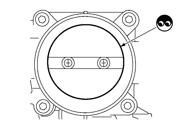
Remove air duct and resonator assembly. Refer to Exploded View.
-
Check if foreign matter is caught between the throttle valve and the housing.
Is the inspection result normal?
YES>>Replace malfunctioning electric throttle control actuator. Refer to Exploded View.
NO>>-
Remove the foreign matter and clean the electric throttle control actuator inside.
-
Perform throttle valve closed position leaning. Refer to Description.
P12a9 Hvac Communication Nissan Pathfinder
DTC Description
DTC DETECTION LOGIC
| DTC |
CONSULT screen terms (Trouble diagnosis content) |
DTC detection condition | ||
| P12A9 | 00 |
HVAC communication (HVAC communication) |
Diagnosis condition | Engine speed less than 650 rpm |
| Signal (terminal) | CAN communication signal | |||
| Threshold | When the ambient temperature estimated from the intake air temperature and engine coolant temperature is lower than 0℃ | |||
| Diagnosis delay time | 5 seconds | |||
POSSIBLE CAUSE
A/C auto amp.
FAIL-SAFE
Not applicable
DTC CONFIRMATION PROCEDURE
PRECONDITIONING
If DTC Confirmation Procedure has been previously conducted, always perform the following procedure before conducting the next test.
-
Turn ignition switch OFF and wait at least 10 seconds.
-
Turn ignition switch ON.
-
Turn ignition switch OFF and wait at least 10 seconds.
TESTING CONDITION:
Before performing the following procedure, confirm that battery voltage is 12 V or more at idle.
>>
GO TO 2.
PERFORM DTC CONFIRMATION PROCEDURE
-
Start engine.
-
Set the select lever in P or N range and wait at least 30 seconds.
-
Check DTC.
Is DTC detected?
YES>>Refer to DTC Diagnosis Procedure.
NO-1>>To check malfunction symptom before repair: Refer to Intermittent Incident.
NO-2>>Confirmation after repair: INSPECTION END
DTC Diagnosis Procedure
CHECK CAN COMMUNICATION LINE
Check CAN communication line. Refer to Trouble Diagnosis Flow Chart.
Is the inspection result normal?
YES>>GO TO 2.
NO>>Repair or replace error-detected parts.
CHECK DTC WITH A/C AUTO AMP.
Check DTC with A/C auto amp. Refer to DTC Index.
Is DTC detected?
YES>>Perform trouble shooting relevant to DTC indicated.
NO>>INSPECTION END
P1526 Ascd System Nissan Pathfinder
DTC Description
DTC DETECTION LOGIC
| DTC |
CONSULT screen terms (Trouble diagnosis content) |
DTC detection condition | ||
| P1526 | 00 |
Nissan Pathfinder Vehicle speed sensor (Vehicle speed sensor) |
Diagnosis condition | Ignition switch ON |
| Signal | CAN communication signal | |||
| Threshold | ECM cannot receive a communication signal sent from VDC (Nissan Pathfinder vehicle dynamics control system) | |||
| Diagnosis delay time | 2 seconds or more | |||
POSSIBLE CAUSE
-
Harness or connectors (The CAN communication line is open or shorted.)
-
VDC(Nissan Pathfinder vehicle dynamics control system)
FAIL-SAFE
Not applicable
DTC Confirmation Procedure
PERFORM DTC CONFIRMATION PROCEDURE
-
Turn ignition switch ON and wait at least 3 seconds.
-
Check DTC.
Is DTC detected?
YES>>Refer to DTC Diagnosis Procedure.
NO-1>>To check malfunction symptom before repair: Refer to Intermittent Incident.
NO-2>>Confirmation after repair: INSPECTION END
DTC Diagnosis Procedure
Perform the trouble diagnosis for CAN communication system. Refer to Trouble Diagnosis Flow Chart.
P155b Energy Management Control Nissan Pathfinder 2022
DTC Description
DTC DETECTION LOGIC
| DTC |
CONSULT screen terms (Trouble diagnosis content) | DTC detection condition | ||
|---|---|---|---|---|
| P155B | 00 |
Electrical energy management system (Electrical energy management system) |
Diagnosis condition | Ignition switch ON |
| Signal (terminal) | ECM power supply | |||
| Threshold | Battery voltage measured by ECM below or above threshold. | |||
| Diagnosis delay time | 20 seconds or more | |||
POSSIBLE CAUSE
-
Harness or connectors
-
ECM
-
IPDM E/R
-
Battery
-
Generator
FAIL-SAFE
Not applicable
CONFIRMATION PROCEDURE
CHECK DTC PRIORITY
If DTC P155B is displayed with DTC P155E and P155F first perform the trouble diagnosis for DTC P155E andP155F.
Which DTC is detected?
YES>>Perform diagnosis of applicable.
-
DTC P155E: Refer to DTC Description.
-
DTC P155F: Refer to DTC Description.
GO TO 2.
PRECONDITIONING
If DTC Confirmation Procedure has been previously conducted, always perform the following procedure before conducting the next test.
-
Ignition switch OFF and wait at least 10 seconds.
-
Ignition switch ON.
-
Ignition switch OFF and wait at least 10 seconds.
TESTING CONDITION:
Before performing the following procedure, confirm that battery voltage is more than 11 V at idle.
>>
GO TO 3.
DTC CONFIRMATION PROCEDURE
-
Start engine and let it idle for at least 20 seconds.
-
Check DTC.
Which DTC is detected?
YES>>Refer to DTC Diagnosis Procedure.
NO-1>>To check malfunction symptom before repair: Refer to Intermittent Incident.
NO-2>>Confirmation after repair: INSPECTION END
DTC Diagnosis Procedure
CHECK CHARGE SYSTEM
Check charge system. Refer to Work Flow (Without 165–DSS-5000P) or Work Flow (With 165–DSS-5000P).
Which DTC is detected?
YES>>INSPECTION END
NO>>Repair or replace the error-detected parts.
P155d Generator Nissan Pathfinder R53
DTC Description
DTC DETECTION LOGIC
| DTC |
CONSULT screen terms (Trouble diagnosis content) |
DTC detection condition | |||
| P155D | 00 | GENERATOR | A | Diagnosis condition | Engine running at idle |
| Signal (terminal) | Generator mechanical malfunction signal | ||||
| Threshold | ECM receives mechanical malfunction signal sent from generator | ||||
| Diagnosis delay time | — | ||||
| B | Diagnosis condition | Engine running at idle | |||
| Signal (terminal) | Generator electrical malfunction signal | ||||
| Threshold | ECM receives electrical malfunction signal sent from generator | ||||
| Diagnosis delay time | — | ||||
POSSIBLE CAUSE
Generator
FAIL-SAFE
Not applicable
DTC Confirmation Procedure
PRECONDITIONING
If DTC Confirmation Procedure has been previously conducted. always perform the following procedure before conducting the next test.
-
Turn ignition switch OFF and wait at least 10 seconds.
-
Turn ignition switch ON.
-
Turn ignition switch OFF and wait at least 10 seconds.
>>
GO TO 2.
PERFORM DTC CONFIRMATION PROCEDURE
-
Start the engine and let it idle at least 10 seconds.
-
Check DTC.
Is DTC detected?
YES>>Proceed to DTC Diagnosis Procedure.
NO-1>>To check malfunction symptom before repair: Refer to Intermittent Incident.
NO-2>>Confirmation after repair: INSPECTION END
DTC Diagnosis Procedure
CHECK CHARGING SYSTEM
Perform trouble diagnosis for charging system. Refer to Work Flow (Without 165–DSS-5000P) or Work Flow (With 165–DSS-5000P).
Is the inspection result normal?
YES>>Replace generator. Refer to Removal and Installation.
NO>>Repair or replace error-detected parts.
P1564 Ascd Steering Switch Nissan Pathfinder 2026
DTC Description
DTC DETECTION LOGIC
| DTC |
CONSULT screen terms (Trouble diagnosis content) |
DTC detection condition | ||
| P1564 | 00 |
ASCD SW (ASCD steering switch) |
Diagnosis condition | Ignition switch ON |
| Signal (terminal) | ASCD steering switch signal | |||
| Threshold |
|
|||
| Diagnosis delay time | — | |||
POSSIBLE CAUSE
-
Harness or connectors (ASCD steering switch circuit is open or shorted.)
-
ASCD steering switch
-
ECM
FAIL-SAFE
Not applicable
DTC Confirmation Procedure
CHECK DTC PRIORITY
If DTC P1564 is displayed with DTC P0605, first perform the confirmation procedure (trouble diagnosis) for DTC P0605.
Is DTC P0605 detected?
YES>>
Perform diagnosis for P0605. Refer to DTC Description.
NO>>
GO TO 2.
PRECONDITIONING
If DTC Confirmation Procedure has been previously conducted, always perform the following procedure before conducting the next test.
-
Turn ignition switch OFF and wait at least 10 seconds.
-
Turn ignition switch ON.
-
Turn ignition switch OFF and wait at least 10 seconds.
>>
GO TO 3.
PERFORM DTC CONFIRMATION PROCEDURE
-
Turn ignition switch ON and wait at least 10 seconds.
-
Press MAIN switch for at least 10 seconds, then release it and wait at least 10 seconds.
-
Press CANCEL switch for at least 10 seconds, then release it and wait at least 10 seconds.
-
Press ACCEL/RES switch for at least 10 seconds, then release it and wait at least 10 seconds.
-
Press COAST/SET switch for at least 10 seconds, then release it and wait at least 10 seconds.
-
Check DTC.
Is DTC P1564 detected?
YES>>
Proceed to Diagnosis Procedure.
NO-1>>
To check malfunction symptom before repair: Refer to Intermittent Incident.
NO-2>>
Confirmation after repair: INSPECTION END
Diagnosis Procedure
CHECK DTC PRIORITY
If DTC P1564 is displayed with DTC P0605, first perform the confirmation procedure (trouble diagnosis) for DTC P0605.
Is DTC P0605 detected?
YES>>
Perform diagnosis for P0605. Refer to DTC Description.
NO>>
GO TO 2.
CHECK ASCD STEERING SWITCH CIRCUIT
 With CONSULT
-
Turn ignition switch ON.
-
On CONSULT screen, select “ENGINE”>>“Data Monitor”>>“MAIN SW”, “CANCEL SW”, “RESUME/ACC SW” and “SET SW”.
-
Check each item indication under the following conditions.
Monitor item Condition Indication MAIN SW MAIN switch Pressed ON Released OFF CANCEL SW CANCEL switch Pressed ON Released OFF RESUME/ACC SW ACCEL/RES switch Pressed ON Released OFF SET SW COAST/SET switch Pressed ON Released OFF
 Without CONSULT
-
Turn ignition switch ON.
-
Check the voltage between ECM harness connector terminals as per the following.
ECM Condition Voltage
(Approx.)Connector + – Terminal E32 186
(ASCD steering switch signal)187 MAIN switch: Pressed 0 V CANCEL switch: Pressed 1 V COAST/SET switch: Pressed 2 V ACCEL/RES switch: Pressed 3 V All ASCD steering switches: Released 4 V
Is the inspection result normal?
YES>>
INSPECTION END
NO>>
GO TO 3.
CHECK ASCD STEERING SWITCH GROUND CIRCUIT
-
Turn ignition switch OFF.
-
Disconnect ECM harness connector.
-
Disconnect combination switch (spiral cable) harness connector.
-
Check the continuity between combination switch harness and ECM harness connector.
Combination switch ECM Continuity Connector Terminal Connector Terminal M30 1 E32 187 Existed -
Also check harness for short to power.
Is the inspection result normal?
YES>>
GO TO 4.
NO>>
Repair or replace error-detected parts.
CHECK ASCD STEERING SWITCH INPUT SIGNAL CIRCUIT
-
Check the continuity between combination switch (spiral cable) harness connector and ECM harness connector.
Combination switch ECM Continuity Connector Terminal Connector Terminal M30 8 E32 186 Existed -
Also check harness for short to power and short to ground.
Is the inspection result normal?
YES>>
GO TO 5.
NO>>
Repair or replace error-detected parts.
CHECK COMBINATION SWITCH
Check the continuity between combination switch (spiral cable) connector terminals.
| Combination switch | Continuity | |
|---|---|---|
| Terminal | ||
| 21 | 8 | Existed |
| 36 | 1 | |
Is the inspection result normal?
YES>>
GO TO 6.
NO>>
Replace spiral cable. Refer to Removal and Installation.
CHECK ASCD STEERING SWITCH
Refer to Component Inspection.
Is the inspection result normal?
YES>>
INSPECTION END
NO>>
Replace ASCD steering switch. Refer to Removal and Installation.
Component Inspection
CHECK ASCD STEERING SWITCH
-
Turn ignition switch OFF.
-
Disconnect combination switch (spiral cable) harness connector M149.
-
Check resistance between combination switch harness connector terminals under the following conditions.
Combination switch Condition Resistance
(Approx.)Connector Terminals M149 21 36 MAIN switch: Pressed 0 Ω CANCEL switch: Pressed 250 Ω COAST/SET switch: Pressed 660 Ω ACCEL/RES switch: Pressed 1,480 Ω All ASCD steering switches: Released 4,000 Ω
Is the inspection result normal?
YES>>
INSPECTION END
NO>>
Replace ASCD steering switch. Refer to Removal and Installation.
P1568 Icc Function Nissan Pathfinder 5th Gen
DTC Description
DTC DETECTION LOGIC
| DTC |
CONSULT screen terms (Trouble diagnosis content) |
DTC detection condition | ||
| P1568 | 00 |
ICC COMMAND VALUE (ICC function) |
Diagnosis condition | — |
| Signal (terminal) | ADAS control unit 2 signal | |||
| Threshold | ECM detects a difference between signals from ADAS control unit 2 is out of specified range | |||
| Diagnosis delay time | — | |||
POSSIBLE CAUSE
-
Harness or connectors (CAN communication line is open or shorted.)
-
ADAS control unit 2
-
ECM
FAIL-SAFE
Not applicable
DTC Confirmation Procedure
CHECK DTC PRIORITY
If DTC P1568 is displayed with DTC UXXXX, P0605 or P0607, first perform the confirmation procedure for DTC UXXXX, P0605 or P0607.
Is DTC UXXXX, P0605 or P0607 detected?
YES>>Perform diagnosis of applicable.
-
DTC UXXXX: Refer to DTC Index.
-
DTC P0605: Refer to DTC Description.
-
DTC P0607: Refer to DTC Description.
GO TO 2.
PRECONDITIONING
If DTC Confirmation Procedure has been previously conducted, always perform the following procedure before conducting the next test.
-
Turn ignition switch OFF and wait at least 10 seconds.
-
Turn ignition switch ON.
-
Turn ignition switch OFF and wait at least 10 seconds.
TESTING CONDITION:
Step 4 may be conducted with the drive wheels lifted in the shop or by driving the Nissan Pathfinder vehicle. If a road test is expected to be easier, it is unnecessary to lift the vehicle.
>>
GO TO 3.
PERFORM DTC CONFIRMATION PROCEDURE
-
Turn ignition switch ON.
-
Press MAIN switch on ICC steering switch.
-
Drive the Nissan Pathfinder vehicle at more than 40 km/h (25 MPH).
CAUTION:
Always drive vehicle at a safe speed.
-
Press SET/COAST switch.
-
Check DTC.
Is DTC P1568 detected?
YES>>Proceed to Diagnosis Procedure.
NO-1>>To check malfunction symptom before repair: Refer to Intermittent Incident.
NO-2>>Confirmation after repair: INSPECTION END
Diagnosis Procedure
CHECK DTC PRIORITY
If DTC P1568 is displayed with DTC UXXXX, P0605 or P0607, first perform the confirmation procedure for DTC UXXXX, P0605 or P0607.
Is DTC UXXXX, P0605 or P0607 detected?
YES>>Perform diagnosis of applicable.
-
DTC UXXXX: Refer to DTC Index.
-
DTC P0605: Refer to DTC Description.
-
DTC P0607: Refer to DTC Description.
GO TO 2.
REPLACE ADAS CONTROL UNIT 2
-
Replace ADAS control unit 2.
-
Perform Work Procedure.
-
Check DTC of ADAS control unit 2. Refer to CONSULT Function (ICC/ADAS 2)(Without ProPILOT system) or CONSULT Function (ICC/ADAS 2) (With ProPILOT system).
>>
INSPECTION END
P1572 Brake Pedal Position Switch Nissan Pathfinder R53
DTC Description
When the brake pedal is depressed, brake pedal position switch is turned OFF and stop lamp switch is turned ON. ECM detects the state of the brake pedal by those two types of input (ON/OFF signal).
Refer to System Description for the ASCD function.
DTC DETECTION LOGIC
| DTC |
CONSULT screen terms (Trouble diagnosis content) |
DTC detection condition | ||
| P1572 | 00 |
ASCD BRAKE SW (Brake pedal position switch) |
Diagnosis condition | Selector lever Suitable position and engine run |
| Signal (terminal) | Brake pedal position switch signal | |||
| Threshold | Brake pedal position switch signal is not sent to ECM for extremely long time | |||
| Diagnosis delay time | — | |||
POSSIBLE CAUSE
-
Harness or connectors (Brake pedal position switch circuit is shorted.)
-
Brake pedal position switch
-
Incorrect brake pedal position switch installation
-
ECM
FAIL-SAFE
Not applicable
DTC Confirmation Procedure
CHECK DTC PRIORITY
If DTC P1572 is displayed with DTC P0605, first perform the confirmation procedure (trouble diagnosis) for DTC P0605.
Is DTC P0605 detected?
YES>>
Perform diagnosis for P0605. Refer to DTC Description.
NO>>
GO TO 2.
PRECONDITIONING
If DTC Confirmation Procedure has been previously conducted, always perform the following procedure before conducting the next test.
-
Turn ignition switch OFF and wait at least 10 seconds.
-
Turn ignition switch ON.
-
Turn ignition switch OFF and wait at least 10 seconds.
>>
GO TO 3.
PERFORM DTC CONFIRMATION PROCEDURE
-
Start engine (VDC switch OFF).
-
Press MAIN switch and make sure that CRUISE lamp illuminates.
-
Drive the Nissan Pathfinder vehicle for at least 5 consecutive seconds under the following conditions.
CAUTION:
Always drive Nissan Pathfinder vehicle at a safe speed.
 NOTE:
NOTE: This procedure may be conducted with the drive wheels lifted in the shop or by driving the Nissan Pathfinder vehicle. If a road test is expected to be easier, it is unnecessary to lift the vehicle.
Nissan Pathfinder Vehicle speed More than 30 km/h (19 mph) Selector lever Suitable position -
Check DTC.
Is DTC P1572 detected?
YES>>
Proceed to Diagnosis Procedure.
NO>>
GO TO 4.
PERFORM DTC CONFIRMATION PROCEDURE
-
Drive the Nissan Pathfinder vehicle for at least 5 consecutive seconds under the following conditions.
CAUTION:
Always drive Nissan Pathfinder vehicle at a safe speed.
 NOTE:
NOTE: This procedure may be conducted with the drive wheels lifted in the shop or by driving the Nissan Pathfinder vehicle. If a road test is expected to be easier, it is unnecessary to lift the vehicle.
Nissan Pathfinder Vehicle speed More than 30 km/h (19 mph) Selector lever Suitable position Driving location Depress the brake pedal for more than 5 seconds so as not to come off from the above-mentioned Nissan Pathfinder vehicle speed. -
Check DTC.
Is DTC P1572 detected?
YES>>
Proceed to Diagnosis Procedure.
NO-1>>
To check malfunction symptom before repair: Refer to Intermittent Incident.
NO-2>>
Confirmation after repair: INSPECTION END
Diagnosis Procedure
CHECK DTC PRIORITY
If DTC P1572 is displayed with DTC P0605, first perform the confirmation procedure (trouble diagnosis) for DTC P0605.
Is DTC P0605 detected?
YES>>
Perform diagnosis for P0605. Refer to DTC Description.
NO>>
GO TO 2.
CHECK OVERALL FUNCTION
 With CONSULT
-
Turn ignition switch ON.
-
Select “BRAKE SW1” and “BRAKE SW2” in “DATA MONITOR” mode of “ENGINE” using CONSULT.
-
Check “BRAKE SW1” and “BRAKE SW2” indication as per the following conditions.
Monitor item Condition Indication BRAKE SW1 Brake pedal Slightly depressed OFF Fully released ON BRAKE SW2 Brake pedal Slightly depressed ON Fully released OFF
 Without CONSULT
-
Turn ignition switch ON.
-
Check the voltage between ECM harness connector terminals as per the following.
ECM Condition Voltage
(Approx.)Connector + – Terminal E32 192
(Brake pedal position switch signal)204 Brake pedal Slightly depressed 0 V Fully released Battery voltage
Is the inspection result normal?
YES>>
GO TO 7.
NO>>
GO TO 3.
CHECK BRAKE PEDAL POSITION SWITCH POWER SUPPLY
-
Turn ignition switch OFF.
-
Disconnect brake pedal position switch harness connector.
-
Turn ignition switch ON.
-
Check the voltage between brake pedal position switch harness connector and ground.
+ − Voltage Brake pedal position switch Connector Terminal E76 1 Ground Battery voltage
Is the inspection result normal?
YES>>
GO TO 6.
NO>>
GO TO 4.
CHECK BRAKE PEDAL POSITION SWITCH POWER SUPPLY CIRCUIT
-
Turn ignition switch OFF.
-
Disconnect fuse block (J/B) harness connector.
-
Check the continuity between brake pedal position switch harness connector and fuse block (J/B) harness connector.
Brake pedal position switch Fuse block (J/B) Continuity Connector Terminal Connector Terminal E76 1 E55 7J Existed -
Also check harness for short to ground.
Is the inspection result normal?
YES>>
GO TO 5.
NO>>
Repair or replace error-detected parts.
CHECK FUSE
Check that the following fuse is not blowing.
| Location | Fuse No. | Capacity |
|---|---|---|
| Fuse block (J/B) | #32 | 10A |
Is the fuse blown (open)?
YES>>
Replace the fuse after repairing the applicable circuit.
NO>>
Perform trouble diagnosis for power supply circuit.
CHECK BRAKE PEDAL POSITION SWITCH INPUT SIGNAL CIRCUIT
-
Turn ignition switch OFF.
-
Disconnect ECM harness connector.
-
Check the continuity between brake pedal position switch harness connector and ECM harness connector.
Brake pedal position switch ECM Continuity Connector Terminal Connector Terminal E76 2 E32 192 Existed -
Also check harness for short to power and short to ground.
Is the inspection result normal?
YES>>
GO TO 7.
NO>>
Repair or replace error-detected parts.
CHECK BRAKE PEDAL POSITION SWITCH
Refer to Component Inspection (Brake Pedal Position Switch)
Is the inspection result normal?
YES>>
Check intermittent incident. Refer to Intermittent Incident.
NO>>
Replace brake pedal position switch. Refer to Exploded View.
Component Inspection (Brake Pedal Position Switch)
CHECK BRAKE PEDAL POSITION SWITCH-I
-
Turn ignition switch OFF.
-
Disconnect brake pedal position harness connector.
-
Check the continuity between brake pedal position switch terminals as per the following conditions.
Brake pedal position switch Condition Continuity Terminal 1 2 Brake pedal Fully released Existed Slightly depressed Not existed
Is the inspection result normal?
YES>>
INSPECTION END
NO>>
GO TO 2.
CHECK BRAKE PEDAL POSITION SWITCH-II
-
Adjust brake pedal position switch installation. Refer to Adjustment.
-
Check the continuity between brake pedal position switch terminals as per the following conditions.
Brake pedal position switch Condition Continuity Terminal 1 2 Brake pedal Fully released Existed Slightly depressed Not existed
Is the inspection result normal?
YES>>
INSPECTION END
NO>>
Replace brake pedal position switch. Refer to Exploded View.
P1574 Ascd Vehicle Speed Sensor Nissan Pathfinder 2026
DTC Description
The ECM receives two vehicle speed signals via the CAN communication line. One is sent from “combination meter”, and the other is from TCM (Transmission control module). The ECM uses these signals for ASCD control. Refer to System Description for ASCD functions.
DTC DETECTION LOGIC
| DTC |
CONSULT screen terms (Trouble diagnosis content) |
DTC detection condition | ||
| P1574 | 00 |
ASCD VHL SPD SEN (ASCD Nissan Pathfinder vehicle speed sensor) |
Diagnosis condition | Nissan Pathfinder Vehicle speed: More than 40 km/h (25 MPH) |
| Signal (terminal) | — | |||
| Threshold | The difference between the two Nissan Pathfinder vehicle speed signals is out of the specified range | |||
| Diagnosis delay time | — | |||
POSSIBLE CAUSE
-
Harness or connectors (CAN communication line is open or shorted.)
-
Combination meter
-
ABS actuator and electric unit (control unit)
-
Wheel sensor
-
TCM
-
ECM
FAIL-SAFE
Not applicable
DTC Confirmation Procedure
CHECK DTC PRIORITY
If DTC P1574 is displayed with DTC UXXXX, P0500, P0605 or P0607, first perform the confirmation procedure (trouble diagnosis) for DTC UXXXX, P0500, P0605 or P0607.
Is DTC UXXXX, P0500, P0605 or P0607 detected?
YES>>Perform diagnosis of applicable.
-
DTC UXXXX: Refer to DTC Index.
-
DTC P0500: Refer to DTC Description.
-
DTC P0605: Refer to DTC Description.
-
DTC P0607: Refer to DTC Description.
GO TO 2.
PRECONDITIONING
If DTC Confirmation Procedure has been previously conducted, always perform the following procedure before conducting the next test.
-
Turn ignition switch OFF and wait at least 10 seconds.
-
Turn ignition switch ON.
-
Turn ignition switch OFF and wait at least 10 seconds.
>>
GO TO 3.
PERFORM DTC CONFIRMATION PROCEDURE
-
Start engine (VDC switch OFF).
-
Drive the Nissan Pathfinder vehicle at more than 40 km/h (25 MPH).
CAUTION:
Always drive vehicle at a safe speed.
 NOTE:
NOTE:
This procedure may be conducted with the drive wheels lifted in the shop or by driving the Nissan Pathfinder vehicle. If a road test is expected to be easier, it is unnecessary to lift the vehicle.
-
Check DTC.
Is DTC P1574 detected?
YES>>Proceed to Diagnosis Procedure.
NO-1>>To check malfunction symptom before repair: Refer to Intermittent Incident.
NO-2>>Confirmation after repair: INSPECTION END
Diagnosis Procedure
CHECK DTC PRIORITY
If DTC P1574 is displayed with DTC UXXXX, P0500, P0605 or P0607, first perform the confirmation procedure (trouble diagnosis) for DTC UXXXX, P0500, P0605 or P0607.
Is DTC UXXXX, P0500, P0605 or P0607 detected?
YES>>Perform diagnosis of applicable.
-
DTC UXXXX: Refer to DTC Index.
-
DTC P0500: Refer to DTC Description.
-
DTC P0605: Refer to DTC Description.
-
DTC P0607: Refer to DTC Description.
GO TO 2.
CHECK DTC WITH TCM
Check DTC with TCM. Refer to CONSULT Function.
Is the inspection result normal?
YES>>GO TO 3.
NO>>Perform trouble shooting relevant to DTC indicated.
CHECK DTC WITH ABS ACTUATOR AND ELECTRIC UNIT (CONTROL UNIT)
Check DTC with ABS actuator and electric unit (control unit). Refer to CONSULT Function.
Is the inspection result normal?
YES>>GO TO 4.
NO>>Repair or replace.
CHECK DTC WITH COMBINATION METER
Check DTC with combination meter.
-
FULL TFT METER: Refer to CONSULT Function (METER/M&A).
-
7 INCH INFORMATION DISPLAY: Refer to CONSULT Function (METER/M&A).
>>
INSPECTION END

Nissan Pathfinder (R53) 2022-2026 Service Manual
Dtc/circuit Diagnosis (P1220 Fuel Pump Control Module (fpcm) ... P1574 Ascd Vehicle Speed Sensor)
- P1220 Fuel Pump Control Module (fpcm)
- P1225 Tp Sensor
- P12a9 Hvac Communication
- P1526 Ascd System
- P155b Energy Management Control
- P155d Generator
- P1564 Ascd Steering Switch
- P1568 Icc Function
- P1572 Brake Pedal Position Switch
- P1574 Ascd Vehicle Speed Sensor
Contact Us
Nissan Pathfinder Info Center
Email: info@nipathfinder.com
Phone: +1 (800) 123-4567
Address: 123 Pathfinder Blvd, Nashville, TN 37214, USA
Working Hours: Mon–Fri, 9:00 AM – 5:00 PM (EST)
