Nissan Pathfinder: Dtc/circuit Diagnosis (Ignition Signal ... Variable Induction Air System)
- Ignition Signal
- Information Display (ascd)
- Malfunction Indicator Lamp
- Mass Air Flow Sensor
- On Board Refueling Vapor Recovery (orvr)
- Refrigerant Pressure Sensor
- Sensor Power Supply 2 Circuit
- Variable Induction Air System
Ignition Signal Nissan Pathfinder R53
Component Function Check
INSPECTION START
Turn ignition switch OFF, and restart engine.
Does the engine start?
YES-1>>
With CONSULT: GO TO 2.
YES-2>>
Without CONSULT: GO TO 3.
No>>
Proceed to Diagnosis Procedure.
CHECK IGNITION SIGNAL FUNCTION
 With CONSULT
-
Perform “POWER BALANCE” in “Active Test” mode of “ENGINE”.
-
Make sure that each circuit produces a momentary engine speed drop.
Is the inspection result normal?
YES>>
INSPECTION END
NO>>
Proceed to Diagnosis Procedure.
CHECK IGNITION SIGNAL FUNCTION
 Without CONSULT
-
Let engine idle.
-
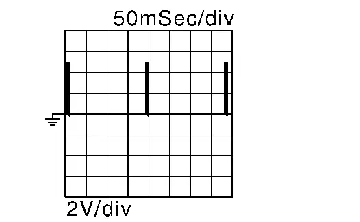
Read the voltage signal between ECM harness connector terminals under the following conditions with an oscilloscope.
ECM Condition Voltage signal + – Connector Terminal Connector Terminal F79 153 E32 204 [Engine is running]
-
Warm-up condition
-
Idle speed
 NOTE:
NOTE: The pulse cycle changes depending on rpm at idle
154 161 162 164 168 -
Is the inspection result normal?
YES>>
INSPECTION END
NO>>
Proceed to Diagnosis Procedure.
Diagnosis Procedure
CHECK FUSE-I
-
Turn ignition switch OFF.
-
Check that the following fuse is not blowing.
Location Fuse No. Capacity IPDM E/R #81 15A
Is the fuse blown (open)?
YES>>
Replace the fuse after repairing the applicable circuit.
NO>>
GO TO 2.
CHECK IGNITION COIL POWER SUPPLY-I
-
Turn ignition switch OFF, wait at least 10 seconds and then turn it ON.
-
Check the voltage between ECM harness connector terminals as per the following.
ECM Voltage Connector + – Terminal E32 185 204 Battery voltage
Is the inspection result normal?
YES>>
GO TO 3.
NO>>
Perform the trouble diagnosis for ECM power supply circuit. Refer to Diagnosis Procedure.
CHECK IGNITION COIL POWER SUPPLY-II
-
Turn ignition switch OFF.
-
Disconnect condenser harness connector.
-
Turn ignition switch ON.
-
Check the voltage between condenser harness connector and ground.
+ − Voltage Condenser Connector Terminal F21 1 Ground Battery voltage
Is the inspection result normal?
YES>>
GO TO 5.
NO>>
GO TO 4.
CHECK IGNITION COIL POWER SUPPLY CIRCUIT-I
-
Turn ignition switch OFF.
-
Disconnect IPDM E/R harness connector.
-
Check the continuity between IPDM E/R harness connector and condenser harness connector.
IPDM E/R Condenser Continuity Connector Terminal Connector Terminal E121 43 F21 1 Existed -
Also check harness for short to power and short to ground.
Is the inspection result normal?
YES>>
Proceed to Intermittent Incident.
NO>>
Repair or replace error-detected parts.
CHECK CONDENSER GROUND CIRCUIT FOR OPEN AND SHORT
-
Turn ignition switch OFF.
-
Check the continuity between condenser harness connector and ground.
Condenser — Continuity Connector Terminal F21 2 Ground Existed -
Also check harness for short to power.
Is the inspection result normal?
YES>>
GO TO 6.
NO>>
Repair or replace error-detected parts.
CHECK CONDENSER
Refer to Component Inspection (Condenser)
Is the inspection result normal?
YES>>
GO TO 7.
NO>>
Replace condenser.
CHECK IGNITION COIL POWER SUPPLY-III
-
Reconnect all harness connectors disconnected.
-
Disconnect ignition coil harness connector.
-
Turn ignition switch ON.
-
Check the voltage between ignition coil harness connector and ground.
+ − Voltage Ignition coil Cylinder Connector Terminal 1 F47 3 Ground Battery voltage 2 F8 3 3 F48 3 4 F9 3 5 F49 3 6 F10 3
Is the inspection result normal?
YES>>
GO TO 9.
NO>>
GO TO 8.
CHECK IGNITION COIL POWER SUPPLY CIRCUIT-II
-
Turn ignition switch OFF.
-
Disconnect IPDM E/R harness connector.
-
Check the continuity between IPDM E/R harness connector and ignition coil harness connector.
IPDM E/R Ignition coil Continuity Connector Terminal Cylinder Connector Terminal E121 43 1 F47 3 Existed 2 F8 3 3 F48 3 4 F9 3 5 F49 3 6 F10 3 -
Also check harness for short to power and short to ground.
Is the inspection result normal?
YES>>
Proceed to Intermittent Incident.
NO>>
Repair or replace error-detected parts.
CHECK IGNITION COIL GROUND CIRCUIT
-
Turn ignition switch OFF.
-
Check the continuity between ignition coil harness connector and ground.
Ignition coil — Continuity Cylinder Connector Terminal 1 F47 2 Ground Existed 2 F8 2 3 F48 2 4 F9 2 5 F49 2 6 F10 2 -
Also check harness for short to power.
Is the inspection result normal?
YES>>
GO TO 10.
NO>>
Repair or replace error-detected parts.
CHECK IGNITION COIL OUTPUT SIGNAL CIRCUIT
-
Disconnect ECM harness connector.
-
Check the continuity between ignition coil harness connector and ECM harness connector.
Ignition coil ECM Continuity Cylinder Connector Terminal Connector Terminal 1 F47 1 F79 161 Existed 2 F8 1 164 3 F48 1 153 4 F9 1 162 5 F49 1 168 6 F10 1 154 -
Also check harness for short to power and short to ground.
Is the inspection result normal?
YES>>
GO TO 11.
NO>>
Repair or replace error-detected parts.
CHECK IGNITION COIL WITH POWER TRANSISTOR
Refer to Component Inspection (Ignition Coil with Power Transistor).
Is the inspection result normal?
YES>>
Check intermittent incident. Refer to Intermittent Incident.
NO>>
Replace malfunctioning ignition coil with power transistor. Refer to Removal and Installation (Bank 2) or Removal and Installation (Bank 1).
Component Inspection (Ignition Coil with Power Transistor)
CHECK IGNITION COIL WITH POWER TRANSISTOR-I
-
Turn ignition switch OFF.
-
Disconnect ignition coil harness connector.
-
Check resistance between ignition coil terminals as per the following.
Ignition coil Condition Resistance Terminal 1 2 Temperature [°C (°F)] 25 (77) Except 0 or ∞Ω 1 3 Except 0 Ω 2 3
Is the inspection result normal?
YES>>
GO TO 2.
NO>>
Replace malfunctioning ignition coil with power transistor. Refer to Removal and Installation (Bank 2) or Removal and Installation (Bank 1).
CHECK IGNITION COIL WITH POWER TRANSISTOR-II
CAUTION:
Perform the following procedure in a place where with no combustible objects and good ventilation.
-
Turn ignition switch OFF.
-
Reconnect all harness connectors disconnected.
-
Pull out 20A fuse (No.85) from IPDM E/R to release fuel pressure. Refer to IPDM E/R Terminal Arrangement .
 NOTE:
NOTE: Do not use CONSULT to release fuel pressure, or fuel pressure applies again during the following procedure.
-
Start engine.
-
After engine stalls, crank it two or three times to release all fuel pressure.
-
Turn ignition switch OFF.
-
Remove all ignition coil harness connectors to avoid the electrical discharge from the ignition coils.
-
Remove ignition coil and spark plug of the cylinder to be checked.
-
Crank engine for 5 seconds or more to remove combustion gas in the cylinder.
-
Connect spark plug and harness connector to ignition coil.
-
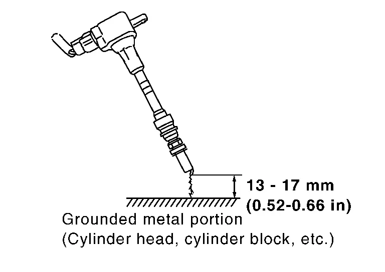
Fix ignition coil using a rope etc. with gap of 13 – 17 mm (0.52 – 0.66 in) between the edge of the spark plug and grounded metal portion as shown in the figure.
-
Crank engine for about three seconds, and check whether spark is generated between the spark plug and the grounded metal portion.
Spark should be generated. CAUTION:
-
Never place the spark plug and the ignition coil within 50 cm (19.7 in) each other. Be careful not to get an electrical shock while checking, because the electrical discharge voltage becomes 20 kV or more.
-
It might damage the ignition coil if the gap of more than 17 mm (0.66 in) is made.
 NOTE:
NOTE: When the gap is less than 13 mm (0.52 in), spark might be generated even if the coil is malfunctioning.
-
Is the inspection result normal?
YES>>
INSPECTION END
NO>>
Replace malfunctioning ignition coil with power transistor. Refer to Removal and Installation (Bank 2) or Removal and Installation (Bank 1).
Component Inspection (Condenser)
CHECK CONDENSER
-
Turn ignition switch OFF.
-
Disconnect condenser harness connector.
-
Check resistance between condenser terminals as per the following.
Condenser Condition Resistance Terminal 1 2 Temperature [°C (°F)] 25 (77) Above 1 MΩ
Is the inspection result normal?
YES>>
INSPECTION END
NO>>
Replace condenser.
Information Display (ascd) Nissan Pathfinder 2022
Component Function Check
CHECK INFORMATION DISPLAY
-
Start engine.
-
Press MAIN switch on ASCD steering switch.
-
Drive the Nissan Pathfinder vehicle at more than 40 km/h (25 MPH).
CAUTION:
Always drive vehicle at a safe speed.
-
Press COAST/SET switch.
-
Check that the reading of the speedometer shows the same value as the set speed indicated in the information display while driving the Nissan Pathfinder vehicle on a flat road.
Is the inspection result normal?
YES>>INSPECTION END
NO>>Proceed to Diagnosis Procedure.
Diagnosis Procedure
CHECK DTC
Check that DTC UXXXX, P0500 or P1574 is not displayed.
Is the inspection result normal?
YES>>GO TO 2.
NO-1>>Perform trouble diagnosis for DTC UXXXX. Refer to DTC Index.
NO-2>>Perform trouble diagnosis for DTC P0500. Refer to DTC Description.
NO-3>>Perform trouble diagnosis for DTC P1574. Refer to DTC Description.
CHECK DTC WITH COMBINATION METER
-
FULL TFT METER: Refer to CONSULT Function (METER/M&A).
-
7 INCH INFORMATION DISPLAY: Refer to CONSULT Function (METER/M&A).
Is the inspection result normal?
YES>>GO TO 3.
NO>>Perform trouble diagnosis for DTC indicated.
CHECK INTERMITTENT INCIDENT
Refer to Intermittent Incident.
Is the inspection result normal?
YES>>Replace combination meter.
-
FULL TFT METER: Refer to Removal and Installation.
-
7 INCH INFORMATION DISPLAY: Refer to Removal and Installation.
Repair or replace.
Malfunction Indicator Lamp Nissan Pathfinder 2022
Component Function Check
CHECK MIL FUNCTION
-
Turn ignition switch ON.
-
Make sure that MIL illuminates.
Is the inspection result normal?
YES>>INSPECTION END
NO>>Proceed to Diagnosis Procedure.
Diagnosis Procedure
CHECK DTC
Check that DTC UXXXX is not displayed.
Is the inspection result normal?
YES>>GO TO 2.
NO>>Perform trouble diagnosis for DTC UXXXX.
CHECK DTC WITH COMBINATION METER
Check DTC with combination meter.
-
FULL TFT METER: Refer to CONSULT Function (METER/M&A).
-
7 INCH INFORMATION DISPLAY: Refer to CONSULT Function (METER/M&A).
Is the inspection result normal?
YES>>GO TO 3.
NO>>Repair or replace.
CHECK INTERMITTENT INCIDENT
Refer to Intermittent Incident.
Is the inspection result normal?
YES>>Replace combination meter. Refer to Removal and Installation.
NO>>Repair or replace.
Mass Air Flow Sensor Nissan Pathfinder Fifth generation
Component Inspection (Mass Air Flow Sensor)
CHECK MASS AIR FLOW SENSOR-I
 With CONSULT
-
Turn ignition switch OFF.
-
Reconnect all harness connectors disconnected.
-
Start engine and warm it up to normal operating temperature.
-
On CONSULT screen, select “ENGINE”>>“Data Monitor”.
-
Check “MASS AIR FLOW SENSOR (Hz)” indication as following.
Monitor item Condition Indication MASS AIR FLOW SENSOR (Hz) Ignition switch ON (Engine stopped.) Approx. 3,700 Hz Idle (Engine is warmed-up to normal operating temperature.) 4,800 – 5,300 Hz 2,500 rpm (Engine is warmed-up to normal operating temperature.) 5,900 – 6,500 Hz Idle to about 4,000 rpm 4,800 – 5,300 Hz → 6,400 – 7,200 Hz
 Without CONSULT
-
Turn ignition switch OFF.
-
Reconnect all harness connectors disconnected.
-
Start engine and warm it up to normal operating temperature.
-
Check the frequency between ECM harness connector terminals under the following conditions.
ECM Condition Frequency Connector + – Terminal Terminal F78 33
[MAF sensor signal]30 Ignition switch ON (Engine stopped.) Approx. 3,700 Hz Idle (Engine is warmed-up to normal operating temperature.) 4,800 – 5,300 Hz 2,500 rpm (Engine is warmed-up to normal operating temperature.) 5,900 – 6,500 Hz Idle to about 4,000 rpm 4,800 – 5,300 Hz → 6,400 – 7,200 Hz
Is the inspection result normal?
YES>>INSPECTION END
NO>>GO TO 2.
CHECK FOR THE CAUSE OF UNEVEN AIR FLOW THROUGH MASS AIR FLOW SENSOR
-
Turn ignition switch OFF.
-
Check for the cause of uneven air flow through mass air flow sensor. Refer to the following.
-
Crushed air ducts
-
Malfunctioning seal of air cleaner element
-
Uneven dirt of air cleaner element
-
Intake valve deposits
-
Improper specification of intake air system parts
-
Is the inspection result normal?
YES>>GO TO 4.
NO>>GO TO 3.
CHECK MASS AIR FLOW SENSOR-II
 With CONSULT
-
Repair or replace malfunctioning part.
-
Start engine and warm it up to normal operating temperature.
-
On CONSULT screen, select “ENGINE”>>“Data Monitor”.
-
Check “MASS AIR FLOW SENSOR (Hz)” indication as following.
Monitor item Condition Indication MASS AIR FLOW SENSOR (Hz) Ignition switch ON (Engine stopped.) Approx. 3,700 Hz Idle (Engine is warmed-up to normal operating temperature.) 4,800 – 5,300 Hz 2,500 rpm (Engine is warmed-up to normal operating temperature.) 5,900 – 6,500 Hz Idle to about 4,000 rpm 4,800 – 5,300 Hz → 6,400 – 7,200 Hz
 Without CONSULT
-
Repair or replace malfunctioning part.
-
Start engine and warm it up to normal operating temperature.
-
Check the frequency between ECM harness connector terminals under the following conditions.
ECM Condition Frequency Connector + – Terminal Terminal F78 33
[MAF sensor signal]30 Ignition switch ON (Engine stopped.) Approx. 3,700 Hz Idle (Engine is warmed-up to normal operating temperature.) 4,800 – 5,300 Hz 2,500 rpm (Engine is warmed-up to normal operating temperature.) 5,900 – 6,500 Hz Idle to about 4,000 rpm 4,800 – 5,300 Hz → 6,400 – 7,200 Hz
Is the inspection result normal?
YES>>INSPECTION END
NO>>GO TO 4.
CHECK MASS AIR FLOW SENSOR-III
 With CONSULT
-
Turn ignition switch OFF.
-
Disconnect mass air flow sensor harness connector and reconnect it again.
-
Start engine and warm it up to normal operating temperature.
-
On CONSULT screen, select “ENGINE”>>“Data Monitor”.
-
Check “MASS AIR FLOW SENSOR (Hz)” indication as following.
Monitor item Condition Indication MASS AIR FLOW SENSOR (Hz) Ignition switch ON (Engine stopped.) Approx. 3,700 Hz Idle (Engine is warmed-up to normal operating temperature.) 4,800 – 5,300 Hz 2,500 rpm (Engine is warmed-up to normal operating temperature.) 5,900 – 6,500 Hz Idle to about 4,000 rpm 4,800 – 5,300 Hz → 6,400 – 7,200 Hz
 Without CONSULT
-
Turn ignition switch OFF.
-
Disconnect mass air flow sensor harness connector and reconnect it again.
-
Start engine and warm it up to normal operating temperature.
-
Check the frequency between ECM harness connector terminals under the following conditions.
ECM Condition Frequency Connector + – Terminal Terminal F78 33
[MAF sensor signal]30 Ignition switch ON (Engine stopped.) Approx. 3,700 Hz Idle (Engine is warmed-up to normal operating temperature.) 4,800 – 5,300 Hz 2,500 rpm (Engine is warmed-up to normal operating temperature.) 5,900 – 6,500 Hz Idle to about 4,000 rpm 4,800 – 5,300 Hz → 6,400 – 7,200 Hz
Is the inspection result normal?
YES>>INSPECTION END
NO>>Clean or replace malfunctioning mass air flow sensor.
On Board Refueling Vapor Recovery (orvr) Nissan Pathfinder 2026
Component Function Check
CHECK ORVR FUNCTION
Check whether the following symptoms are present.
-
Fuel odor from EVAP canister is strong.
-
Cannot refuel/Fuel odor from the fuel filler opening is strong while refueling.
Are any symptoms present?
YES>>
Proceed to Diagnosis Procedure.
NO>>
INSPECTION END
Diagnosis Procedure
INSPECTION START
Check whether the following symptoms are present.
A: Fuel odor from EVAP canister is strong.
B: Cannot refuel/Fuel odor from the fuel filler opening is strong while refueling.
Which symptom is present?
A>>
GO TO 2.
B>>
GO TO 7.
CHECK EVAP CANISTER
-
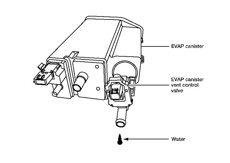
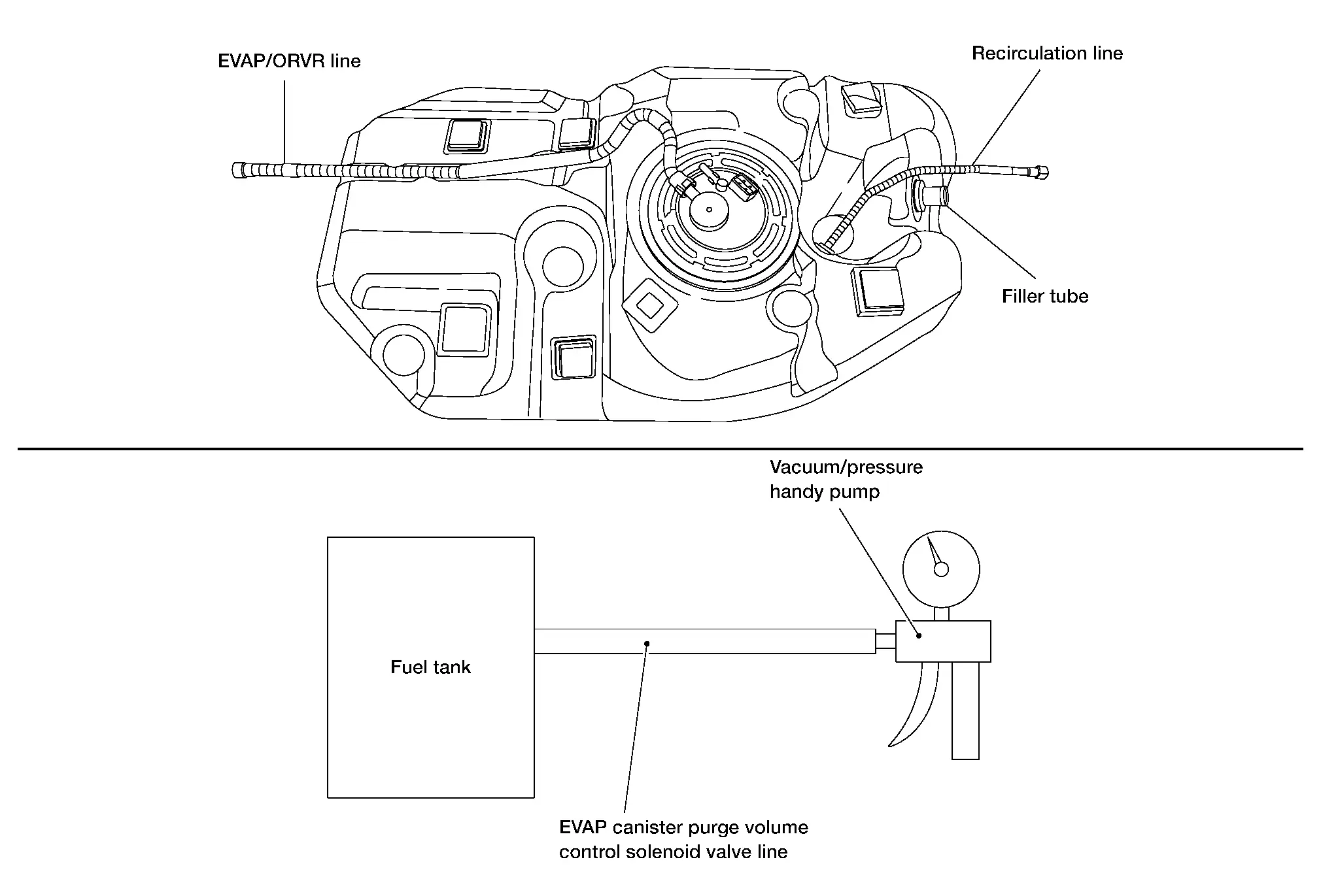
Remove EVAP canister with EVAP canister vent control valve and EVAP control system pressure sensor attached.
-
Weigh the EVAP canister with EVAP canister vent control valve and EVAP control system pressure sensor attached.
The weight should be less than 2.1 kg (4.6 lb).
Is the inspection result normal?
YES>>
GO TO 3.
NO>>
GO TO 4.
CHECK IF EVAP CANISTER IS SATURATED WITH WATER
Check if water will drain from EVAP canister.

Does water drain from the EVAP canister?
YES>>
GO TO 4.
NO>>
GO TO 6.
REPLACE EVAP CANISTER
Replace EVAP canister with a new one.
>>
GO TO 5.
DETECT MALFUNCTIONING PART
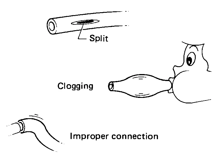
Check the EVAP hose between EVAP canister and Nissan Pathfinder vehicle frame for clogging or poor connection.
>>
Repair or replace EVAP hose.
CHECK REFUELING EVAP VAPOR CUT VALVE
Refer to Component Inspection.
Is the inspection result normal?
YES>>
INSPECTION END
NO>>
Replace refueling EVAP vapor cut valve with fuel tank. Refer to Removal and Installation.
CHECK EVAP CANISTER
-
Remove EVAP canister with EVAP canister vent control valve and EVAP control system pressure sensor attached.
-
Weigh the EVAP canister with EVAP canister vent control valve and EVAP control system pressure sensor attached.
The weight should be less than 2.1 kg (4.6 lb).
Is the inspection result normal?
YES>>
GO TO 8.
NO>>
GO TO 9.
CHECK IF EVAP CANISTER IS SATURATED WITH WATER
Check if water will drain from EVAP canister.
Does water drain from the EVAP canister?
YES>>
GO TO 9.
NO>>
GO TO 11.
REPLACE EVAP CANISTER
Replace EVAP canister with a new one.
>>
GO TO 10.
DETECT MALFUNCTIONING PART
Check the EVAP hose between EVAP canister and Nissan Pathfinder vehicle frame for clogging or poor connection.
>>
Repair or replace EVAP hose.
CHECK VENT HOSES AND VENT TUBES
Check hoses and tubes between EVAP canister and refueling control valve for clogging, kinks, looseness and improper connection.
Is the inspection result normal?
YES>>
GO TO 12.
NO>>
Repair or replace hoses and tubes.
CHECK FILLER NECK TUBE
Check recirculation line for clogging, dents and cracks.
Is the inspection result normal?
YES>>
GO TO 13.
NO>>
Replace filler neck tube.
CHECK REFUELING EVAP VAPOR CUT VALVE
Refer to Component Inspection.
Is the inspection result normal?
YES>>
GO TO 14.
NO>>
Replace refueling EVAP vapor cut valve with fuel tank. Refer to Removal and Installation.
CHECK FUEL FILLER TUBE
Check filler neck tube and hose connected to the fuel tank for clogging, dents and cracks.
Is the inspection result normal?
YES>>
GO TO 15.
NO>>
Replace fuel filler tube. Refer to Exploded View.
CHECK ONE-WAY FUEL VALVE-I
Check one-way valve for clogging.
Is the inspection result normal?
YES>>
GO TO 16.
NO>>
Repair or replace one-way fuel valve with fuel tank. Refer to Removal and Installation.
CHECK ONE-WAY FUEL VALVE-II
-
Make sure that fuel is drained from the tank.
-
Remove fuel filler tube and hose.
-
Check one-way fuel valve for operation as follows.
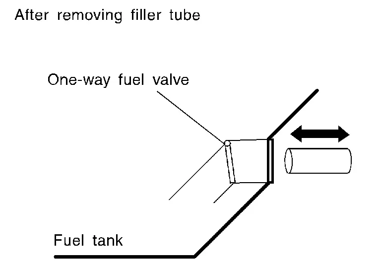
When a stick is inserted, the valve should open, when removing stick it should close.
Do not drop any material into the tank.
Is the inspection result normal?
YES>>
INSPECTION END
NO>>
Replace fuel filler tube or replace one-way fuel valve with fuel tank. Refer to Removal and Installation.
Component Inspection
INSPECTION START
Do you have CONSULT?
Do you have CONSULT?
YES>>
GO TO 2.
NO>>
GO TO 3.
CHECK REFUELING EVAP VAPOR CUT VALVE
 With CONSULT
-
Turn ignition switch OFF.
-
Remove fuel tank. Refer to Removal and Installation.
-
Drain fuel from the tank as follows:
-
Remove fuel feed hose located on the fuel gauge retainer.
-
Connect a spare fuel hose, one side to fuel gauge retainer where the hose was removed and the other side to a fuel container.
-
Drain fuel using “FPCM” in “Active test” mode of “ENGINE”.
-
-
Check refueling EVAP vapor cut valve for being stuck to close as follows.
Blow air into the refueling EVAP vapor cut valve (from the end of EVAP/ORVR line hose), and check that the air flows freely into the tank.
-
Check refueling EVAP vapor cut valve for being stuck to open as follows.
-
Connect vacuum pump to hose end.
-
Remove fuel gauge retainer with fuel gauge unit.
Always replace O-ring with new one.
-
Turn fuel tank upside down.
-
Apply vacuum pressure to hose end [−13.3 kPa (−0.136 kg/cm3, −1.93 psi)] with fuel gauge retainer remaining open and check that the pressure is applicable.

-
Is the inspection result normal?
YES>>
INSPECTION END
NO>>
Replace refueling EVAP vapor cut valve with fuel tank.
CHECK REFUELING EVAP VAPOR CUT VALVE
 Without CONSULT
-
Turn ignition switch OFF.
-
Remove fuel tank. Refer to Removal and Installation.
-
Drain fuel from the tank as follows:
-
Remove fuel gauge retainer.
-
Drain fuel from the tank using a handy pump into a fuel container.
-
-
Check refueling EVAP vapor cut valve for being stuck to close as follows.
Blow air into the refueling EVAP vapor cut valve (from the end of EVAP/ORVR line hose), and check that the air flows freely into the tank.
-
Check refueling EVAP vapor cut valve for being stuck to open as follows.
-
Connect vacuum pump to hose end.
-
Remove fuel gauge retainer with fuel gauge unit.
Always replace O-ring with new one.
-
Turn fuel tank upside down.
-
Apply vacuum pressure to hose end [−13.3 kPa (−0.136 kg/cm3, −1.93 psi)] with fuel gauge retainer remaining open and check that the pressure is applicable.
-
Is the inspection result normal?
YES>>
INSPECTION END
NO>>
Replace refueling EVAP vapor cut valve with fuel tank. Refer to Removal and Installation.
Refrigerant Pressure Sensor Nissan Pathfinder 5th Gen
Component Function Check
CHECK REFRIGERANT PRESSURE SENSOR FUNCTION
-
Start engine and warm it up to normal operating temperature.
-
Turn A/C switch and blower fan switch ON.
-
Check the voltage between ECM harness connector terminals as per the following.
ECM Condition Voltage + – Connector Terminal Connector Terminal F79 108
(Refrigerant pressure sensor signal)F79 125 [Engine is running]
-
Warm-up condition
-
Idle speed
-
Both A/C switch and blower fan motor switch: ON (Compressor operates)
1.0 – 4.0 V -
Is the inspection result normal?
YES>>INSPECTION END
NO>>Proceed to Diagnosis Procedure.
Diagnosis Procedure
CHECK GROUND CONNECTION
-
Turn A/C switch and blower fan switch OFF.
-
Turn ignition switch OFF.
-
Check ground connection E9. Refer to Ground Inspection in Circuit Inspection.
Is the inspection result normal?
YES>>GO TO 2.
NO>>Repair or replace ground connection.
CHECK REFRIGERANT PRESSURE SENSOR POWER SUPPLY
-
Disconnect refrigerant pressure sensor harness connector.
-
Turn ignition switch ON.
-
Check the voltage between refrigerant pressure sensor harness connector and ground.
+ − Voltage
(Approx.)Refrigerant pressure sensor Connector Terminal E244 1 Ground 5 V
Is the inspection result normal?
YES>>GO TO 5.
NO>>GO TO 3.
CHECK REFRIGERANT PRESSURE SENSOR POWER SUPPLY CIRCUIT
-
Turn ignition switch OFF.
-
Disconnect ECM harness connector.
-
Check the continuity between refrigerant pressure sensor harness connector and ECM harness connector.
Refrigerant pressure sensor ECM Continuity Connector Terminal Connector Terminal E244 1 F79 136 Existed -
Also check harness for short to power and short to ground.
Is the inspection result normal?
YES>>GO TO 4.
NO>>Repair or replace error-detected parts.
CHECK SENSOR POWER SUPPLY 2 CIRCUIT
Refer to Diagnosis Procedure.
Is the inspection result normal?
YES>>Perform the trouble diagnosis for ECM power supply circuit. Refer to Diagnosis Procedure.
NO>>Repair or replace error-detected parts.
CHECK REFRIGERANT PRESSURE SENSOR GROUND CIRCUIT
-
Turn ignition switch OFF.
-
Disconnect ECM harness connector.
-
Check the continuity between refrigerant pressure sensor harness connector and ECM harness connector.
Refrigerant pressure sensor ECM Continuity Connector Terminal Connector Terminal E244 3 F79 125 Existed -
Also check harness for short to power and short to ground.
Is the inspection result normal?
YES>>GO TO 6.
NO>>Repair or replace error-detected parts.
CHECK REFRIGERANT PRESSURE SENSOR INPUT SIGNAL CIRCUIT FOR OPEN AND SHORT
-
Check the continuity between refrigerant pressure sensor harness connector and ECM harness connector.
Refrigerant pressure sensor ECM Continuity Connector Terminal Connector Terminal E244 2 F79 108 Existed -
Also check harness for short to power and short to ground.
Is the inspection result normal?
YES>>GO TO 7.
NO>>Repair or replace error-detected parts.
CHECK INTERMITTENT INCIDENT
Refer to Intermittent Incident.
Is the inspection result normal?
YES>>Replace refrigerant pressure sensor. Refer to Exploded View.
NO>>Repair or replace error-detected parts.
Sensor Power Supply 2 Circuit Nissan Pathfinder Fifth generation
Diagnosis Procedure
ECM supplies a voltage of 5 V to some of the sensors systematically divided into 3 groups, respectively. Accordingly, when a short circuit develops in a sensor power source, a malfunction may occur simultaneously in the sensors belonging to the same group as the short-circuited sensor.
Sensor power supply 1
-
APP sensor 1
-
Crankshaft position sensor 1
-
Exhaust camshaft position sensor (bank 1)
-
Throttle position sensor
-
Mass air flow sensor
-
Intake camshaft position sensor (bank 1)
-
Engine oil pressure sensor
 NOTE:
NOTE:
If sensor power supply 1 circuit is malfunctioning, DTC P0643 is displayed.
Sensor power supply 2
-
APP sensor 2
-
Intake camshaft position sensor (bank2)
-
Refrigerant pressure sensor
-
Crankshaft position sensor 2
-
Exhaust camshaft position sensor (bank 2)
-
Fuel rail pressure sensor
Sensor power supply 3
-
EVAP control system pressure sensor
CHECK ECM POWER SUPPLY AND GROUND CIRCUIT
Perform trouble diagnosis for ECM power supply and ground circuit. Refer to Diagnosis Procedure.
Is the inspection result normal?
YES>>GO TO 2.
NO>>Repair or replace error-detected parts.
CHECK APP SENSOR 2 POWER SUPPLY CIRCUIT-1
-
Turn ignition switch OFF.
-
Disconnect accelerator pedal position (APP) sensor harness connector.
-
Turn ignition switch ON.
-
Check the voltage between APP sensor harness connector and ground.
+ - Voltage
(Approx.)APP sensor Connector Terminal E31 5 Ground 5V
Is the inspection result normal?
YES>>Refer to Intermittent Incident.
NO>>GO TO 3.
CHECK APP SENSOR 2 POWER SUPPLY CIRCUIT-2
-
Turn ignition switch OFF.
-
Disconnect ECM harness connector.
-
Check the continuity between APP sensor harness connector and ECM harness connector.
+ + Continuity APP sensor ECM Connector Terminal Connector Terminal E25 2 E21 150 Existed
Is the inspection result normal?
YES>>GO TO 4.
NO>>Repair open circuit.
CHECK SENSOR POWER SUPPLY 2 CIRCUIT
-
Disconnect following sensors harness connector.
-
Check harness for short to power and short to ground, between the following terminals.
| ECM | Sensor | |||
|---|---|---|---|---|
| Connector | Terminal | Name | Connector | Terminal |
| F78 | 60 | Intake camshaft position sensor (bank 2) | F37 | 1 |
| 63 | Crankshaft position sensor 2 | F91 | 1 | |
| 65 | Exhaust camshaft position sensor (bank 2) | F40 | 1 | |
| 66 | Fuel rail pressure sensor | F97 | 3 | |
| F79 | 136 | Refrigerant pressure sensor | E244 | 1 |
| E32 | 194 | APP sensor 2 | E31 | 5 |
Is the inspection result normal?
YES>>GO TO 5.
NO>>Repair short to ground or short to power in harness or connectors.
CHECK COMPONENTS
Check the following.
-
APP sensor 2 (Refer to Component Inspection (Accelerator Pedal Position Sensor).)
-
Intake camshaft position sensor (Refer to Component Inspection.)
-
Refrigerant pressure sensor (Refer to Component Function Check.)
-
Crankshaft position sensor 2 (Refer to Component Inspection (Crankshaft Position Sensor 2).)
-
Exhaust camshaft position sensor (bank 2) (Refer to Component Inspection.)
-
Fuel rail pressure sensor (Refer to Component Inspection (Fuel Rail Pressure Sensor).)
Is the inspection result normal?
YES>>Refer to Intermittent Incident.
NO>>Replace malfunctioning component.
Variable Induction Air System Nissan Pathfinder SUV
Component Function Check
CHECK OVERALL FUNCTION-I
 With CONSULT
-
Start engine and warm it up to the normal operating temperature.
-
Perform “VIAS S/V-1” in “Active Test” mode of “ENGINE” with CONSULT.
-
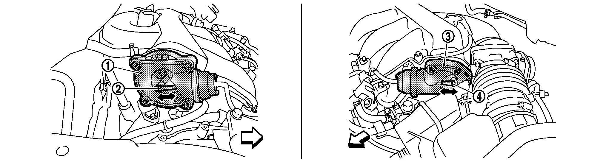
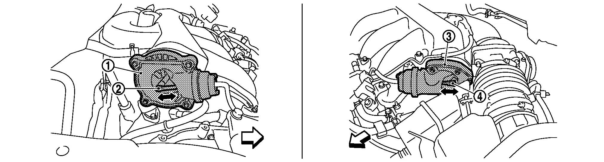
Turn VIAS control solenoid valve 1 “ON” and “OFF”, and check that power valve actuator 1 rod moves.


Power valve actuator 1 
Power valve actuator 1 rod 
Power valve actuator 2 
Power valve actuator 2 rod 
: Nissan Pathfinder Vehicle front
 Without CONSULT
-
Start engine and warm it up to the normal operating temperature.
-
Rev engine quickly up to approximately 5,000 rpm.
-
Check that power valve actuator 1 rod moves.


Power valve actuator 1 
Power valve actuator 1 rod 
Power valve actuator 2 
Power valve actuator 2 rod 
: Nissan Pathfinder Vehicle front
Is the inspection result normal?
YES>>GO TO 2.
NO>>Diagnosis Procedure.
CHECK OVERALL FUNCTION-II
 With CONSULT
-
Perform “VIAS S/V-2” in “Active Test” mode of “ENGINE” with CONSULT.
-
Turn VIAS control solenoid valve 2 “ON” and “OFF”, and check that power valve actuator 2 rod moves.

Power valve actuator 1 
Power valve actuator 1 rod 
Power valve actuator 2 
Power valve actuator 2 rod 
: Nissan Pathfinder Vehicle front
 Without CONSULT
-
When revving engine up to 5,000 rpm quickly.
-
Rev engine quickly up to approximately 5,000 rpm.
-
Check that power valve actuator 2 rod moves.

Power valve actuator 1 
Power valve actuator 1 rod 
Power valve actuator 2 
Power valve actuator 2 rod 
: Nissan Pathfinder Vehicle front
Is the inspection result normal?
YES>>INSPECTION END
NO>>Diagnosis Procedure.
Diagnosis Procedure
INSPECTION START
Confirm the malfunctioning system (power valve 1 or power valve 2). Refer to Component Function Check.
Which system is related to the incident?
Power valve 1>>GO TO 2.
Power valve 2>>GO TO 6.
CHECK VACUUM EXISTENCE-I
 With CONSULT
-
Stop engine and disconnect vacuum hose connected to power valve actuator 1.
-
Start engine and let it idle.
-
Perform “VIAS S/V-1” in “Active Test” mode of “ENGINE” with CONSULT.
-
Turn VIAS control solenoid valve 1 ON and OFF, and check vacuum existence under the following conditions.
VIAS S/V-1 Vacuum ON Existed OFF Not existed
 Without CONSULT
-
Stop engine and disconnect vacuum hose connected to power valve actuator 1.
-
Disconnect VIAS control solenoid valve 1 harness connector.
-
Start engine.
-
Rev engine quickly up to approximately 5,000 rpm.
-
Check vacuum existence under the following conditions.
Condition Vacuum Idle Existed Rev engine quickly up to approximately 5,000 rpm Not existed
Is the inspection result normal?
YES>>Repair or replace power valve actuator 1. Refer to Component Parts Location.
NO>>GO TO 3.
CHECK VACUUM TANK
-
Stop engine and disconnect vacuum hose connected to intake manifold collector.
-
Start engine and let it idle.
-
Check vacuum existence from intake manifold collector.
Does vacuum existence from the intake manifold collector?
YES>>GO TO 4.
NO>>Replace intake manifold collector. Refer to Removal and Installation.
CHECK VACUUM HOSE
-
Stop engine.
-
Check vacuum hose for crack, clogging, improper connection or disconnection. Refer to System Description.

Is the inspection result normal?
YES>>GO TO 5.
NO>>Repair hoses or tubes.
CHECK VIAS CONTROL SOLENOID VALVE 1
Check VIAS control solenoid valve 1. Refer to Component Inspection.
Is the inspection result normal?
YES>>GO TO 8.
NO>>Replace VIAS control solenoid valve 1. Refer to Component Parts Location.
CHECK VACUUM EXISTENCE-II
 With CONSULT
-
Stop engine and disconnect vacuum hose connected to power valve actuator 2.
-
Start engine and let it idle.
-
Perform “VIAS S/V-2” in “Active Test” mode of “ENGINE” with CONSULT.
-
Turn VIAS control solenoid valve 2 ON and OFF, and check vacuum existence under the following conditions.
VIAS S/V 2 Vacuum ON Existed OFF Not existed
 Without CONSULT
-
Stop engine and disconnect vacuum hose connected to power valve actuator 2.
-
Disconnect VIAS control solenoid valve 1 harness connector.
-
Start engine.
-
Rev engine quickly up to approximately 5,000 rpm.
-
Check vacuum existence under the following conditions.
Condition Operation Idle Existed Rev engine quickly up to approximately 5,000 rpm Not existed
Is the inspection result normal?
YES>>Repair or replace power valve actuator 2. Refer to Component Parts Location.
NO>>GO TO 7.
CHECK VACUUM HOSE
-
Stop engine.
-
Check vacuum hose for crack, clogging, improper connection or disconnection. Refer to System Description.
Is the inspection result normal?
YES>>GO TO 8.
NO>>Repair hoses or tubes.
CHECK VIAS CONTROL SOLENOID VALVE 2
Check VIAS control solenoid valve 2. Refer to Component Inspection.
Is the inspection result normal?
YES>>Check intermittent incident. Refer to Intermittent Incident.
NO>>Replace VIAS control solenoid valve 2. Refer to Component Parts Location.

Nissan Pathfinder (R53) 2022-2026 Service Manual
Dtc/circuit Diagnosis (Ignition Signal ... Variable Induction Air System)
- Ignition Signal
- Information Display (ascd)
- Malfunction Indicator Lamp
- Mass Air Flow Sensor
- On Board Refueling Vapor Recovery (orvr)
- Refrigerant Pressure Sensor
- Sensor Power Supply 2 Circuit
- Variable Induction Air System
Contact Us
Nissan Pathfinder Info Center
Email: info@nipathfinder.com
Phone: +1 (800) 123-4567
Address: 123 Pathfinder Blvd, Nashville, TN 37214, USA
Working Hours: Mon–Fri, 9:00 AM – 5:00 PM (EST)
