Nissan Pathfinder: Dtc/circuit Diagnosis (Active Grille Shutter ... High Pressure Fuel Pump)
- Active Grille Shutter
- Ascd Indicator
- Cooling Fan
- Crankshaft Position Sensor 2
- Electrical Load Signal
- Electronic Controlled Engine Mount
- Fuel Injector
- Fuel Pump
- High Pressure Fuel Pump
Active Grille Shutter Nissan Pathfinder
Component Inspection
CHECK ACTIVE GRILLE SHUTTER
 With CONSULT
-
Start the engine.
-
Select “ACTIVE GRILLE SHUTTER” in “ACTIVE TEST” mode of “ENGINE” using CONSULT.
-
Touch “CALIBRTN”.
-
After the calibration completes, check the operation of active grille shutter as follows.
Condition Active grille shutter Select “CLOSE” Open → Close Select “OPEN” Close → Open
 Without CONSULT
-
Turn ignition switch OFF.
-
Operate shutter by hands to close position.
-
Check the operation of active grille shutter as follows.
Condition Active grille shutter Ignition switch: ON Close → Open
Is the inspection result normal?
YES>>INSPECTION END
NO>>Replace active grille shutter. Refer to Removal and Installation.
Ascd Indicator Nissan Pathfinder 2026
Component Function Check
CHECK ASCD INDICATOR FUNCTION
Check ASCD indicator under the following conditions.
| ASCD INDICATOR | CONDITION | SPECIFICATION | |
|---|---|---|---|
| CRUISE LAMP |
|
|
ON → OFF |
| SET LAMP |
|
|
ON |
|
OFF | ||
Is the inspection result normal?
YES>>INSPECTION END
NO>>Proceed to Diagnosis Procedure.
Diagnosis Procedure
CHECK DTC
Check that DTC UXXXX is not displayed.
Is the inspection result normal?
YES>>GO TO 2.
NO>>Perform trouble diagnosis for DTC UXXXX.
CHECK DTC WITH COMBINATION METER
Check DTC with combination meter.
-
FULL TFT METER: Refer to CONSULT Function (METER/M&A).
-
7 INCH INFORMATION DISPLAY: Refer to CONSULT Function (METER/M&A).
Is the inspection result normal?
YES>>GO TO 3.
NO>>Repair or replace.
CHECK INTERMITTENT INCIDENT
Refer to Intermittent Incident.
Is the inspection result normal?
YES>>Replace combination meter.
-
FULL TFT METER: Refer to Removal and Installation.
-
7 INCH INFORMATION DISPLAY: Refer to Removal and Installation.
Repair or replace.
Cooling Fan Nissan Pathfinder 2026
Component Function Check
CHECK COOLING FAN FUNCTION
 With CONSULT
-
Turn ignition switch ON.
-
On CONSULT screen, select “ENGINE ”>>“Active Test”>>“FAN DUTY CONTROL”.
-
Make sure that cooling fan speed varies according to the percentage.
 Without CONSULT
-
Perform IPDM E/R auto active test and check cooling fan motors operation, refer to CONSULT Function (IPDM E/R).
-
Make sure that cooling fan operates.
Is the inspection result normal?
YES>>
INSPECTION END
NO>>
Proceed to Diagnosis Procedure (Cooling Fan Motor).
Diagnosis Procedure (Cooling Fan Motor)
CHECK COOLING FAN CONTROL MODULE POWER SUPPLY-I
-
Turn ignition switch OFF.
-
Disconnect cooling fan control module harness connector.
-
Turn ignition switch ON.
-
Check the voltage between cooling fan control module harness connector and ground.
+ − Voltage Cooling fan control module Connector Terminal E225 3 Ground Battery voltage
Is the inspection result normal?
YES>>
GO TO 11.
NO>>
GO TO 2.
CHECK COOLING FAN CONTROL MODULE POWER SUPPLY-II
-
Turn ignition switch OFF.
-
Remove cooling fan relay.
-
Check the voltage between cooling fan relay harness connector and ground.
+ − Voltage Cooling fan relay Connector Terminal E82 3 Ground Battery voltage
Is the inspection result normal?
YES>>
GO TO 4.
NO>>
GO TO 3.
CHECK FUSIBLE LINK
Check that 60A fusible link (No. H) is not blowing.
Is the fusible link blown (open)?
YES>>
Perform trouble diagnosis for power supply circuit.
NO>>
Replace the fusible link after repairing the applicable circuit.
CHECK COOLING FAN CONTROL MODULE POWAR SUPPLY CIRCUIT
-
Check the continuity between cooling fan relay harness connector and cooing fan control module harness connector.
Cooling fan relay Cooling fan control module Continuity Connector Terminal Connector Terminal E82 5 E225 3 Existed -
Also check harness for short to power and short to ground.
Is the inspection result normal?
YES>>
GO TO 5.
NO>>
Repair or replace error-detected parts.
CHECK COOLING FAN RELAY DRIVE POWER SUPPLY
-
Turn ignition switch ON.
-
Check the voltage between cooling fan relay harness connector and ground.
+ − Voltage Cooling fan relay Connector Terminal E82 1 Ground Battery voltage
Is the inspection result normal?
YES>>
GO TO 8.
NO>>
GO TO 6.
CHECK FUSE
-
Turn ignition switch OFF.
-
Check that 10A fuse (No. 9) is not blowing.
Is the fuse blown (open)?
YES>>
GO TO 7.
NO>>
Replace the fuse after repairing the applicable circuit.
CHECK COOLING FAN RELAY DRIVE POWER SUPPLY CIRCUIT
-
Turn ignition switch OFF.
-
Disconnect fuse block (J/B) harness connector.
-
Check the continuity between fuse block (J/B) harness connector and cooing fan relay harness connector.
Fuse block (J/B) Cooling fan relay Continuity Connector Terminal Connector Terminal E28 1R E82 1 Existed -
Also check harness for short to power and short to ground.
Is the inspection result normal?
YES>>
GO TO 10
NO>>
Repair or replace error-detected parts.
CHECK COOLING FAN RELAY DRIVE SIGNAL CIRCUIT
-
Turn ignition switch OFF.
-
Disconnect IPDM E/R harness connector.
-
Check the continuity between IPDM E/R harness connector and cooing fan relay harness connector.
IPDM E/R Cooling fan relay Continuity Connector Terminal Connector Terminal E78 107 E82 2 Existed -
Also check harness for short to power and short to ground.
Is the inspection result normal?
YES>>
GO TO 9.
NO>>
Repair or replace error-detected parts.
CHECK COOLING FAN RELAY
Refer to Component Inspection (Cooling Fan Relay).
Is the inspection result normal?
YES>>
GO TO 10.
NO>>
Replace cooling fan relay.
CHECK INTERMITTENT INCIDENTE
Perform Intermittent Incident.
Is the inspection result normal?
YES>>
Replace IPDM E/R. Refer to Removal and Installation.
NO>>
Repair or replace error-detected parts.
CHECK COOLING FAN CONTROL MODULE GROUND CIRCUIT
-
Turn ignition switch OFF.
-
Check the continuity between cooling fan control module harness circuit.
Cooling fan control module — Continuity Connector Terminal E225 1 Ground Existed -
Also check harness for short to power.
Is the inspection result normal?
YES>>
GO TO 12.
NO>>
Repair or replace error-detected parts.
CHECK COOLING FAN CONTROL SIGNAL
-
Reconnect cooling fan control module harness connector.
-
Start engine.
-
Check the voltage between IPDM E/R harness connector and ground.
+ − Condition Voltage IPDM E/R Connector Terminal E78 106 Ground Engine idling 0 – 5 V
Is the inspection result normal?
YES>>
GO TO 13.
NO>>
GO TO 10.
CHECK COOLING FAN CONTROL SIGNAL CIRCUIT
-
Turn ignition switch OFF.
-
Disconnect IPDM E/R harness connector and cooling fan control module harness connector.
-
Check the continuity between IPDM E/R harness connector and cooing fan control module harness connector.
IPDM E/R Cooling fan control module Continuity Connector Terminal Connector Terminal E78 106 E225 2 Existed -
Also check harness for short to power and short to ground.
Is the inspection result normal?
YES>>
GO TO 14.
NO>>
Repair or replace error-detected parts.
CHECK COOLING FAN CONTROL MODULE OUTPUT SIGNAL
-
Reconnect all harness connectors disconnected.
-
Disconnect cooling fan control module harness connector.
-
Turn ignition switch ON.
-
Check the voltage between cooling fan control module connector and ground.
+ − Voltage Cooling fan control module Motor Connector Terminal 1 E245 4 Ground Battery voltage 2 E246 6
Is the inspection result normal?
YES>>
GO TO 15.
NO>>
Replace cooling fan control module. Refer to Exploded View.
CHECK COOLING FAN MOTOR
Refer to Component Inspection (Cooling Fan Motor).
Is the inspection result normal?
YES>>
Perform intermittent incident. Refer to Intermittent Incident
NO>>
Replace malfunctioning cooling fan motor. Refer to Exploded View.
Component Inspection (Cooling Fan Motor)
COOING FAN MOTOR 1
CHECK COOLING FAN MOTOR 1
-
Turn ignition switch OFF.
-
Disconnect cooling fan control module harness connector.
-
Supply cooling fan control module harness connector terminals with battery voltage and check operation.
Cooling fan control module Operation Connector + − Terminal E245 4 5 Cooling fan operates.
Is the inspection result normal?
YES>>
INSPECTION END
NO>>
Replace cooling fan motor 1. Refer to Exploded View.
COOING FAN MOTOR 2
CHECK COOLING FAN MOTOR 2
-
Turn ignition switch OFF.
-
Disconnect cooling fan control module harness connector.
-
Supply cooling fan control module harness connector terminals with battery voltage and check operation.
Cooling fan control module Operation Connector + − Terminal E246 6 7 Cooling fan operates.
Is the inspection result normal?
YES>>
INSPECTION END
NO>>
Replace cooling fan motor 2. Refer to Exploded View.
Component Inspection (Cooling Fan Relay)
CHECK COOLING FAN RELAY
-
Turn ignition switch OFF.
-
Remove cooling fan relay.
-
Check the continuity between cooling fan relay terminals under the following conditions.
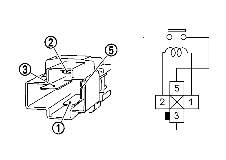
Terminals Conditions Continuity  and
and 
12 V direct current supply between terminals  and
and 
Existed No current supply Not existed
Is the inspection result normal?
YES>>
INSPECTION END
NO>>
Replace malfunctioning cooling fan relay.
Crankshaft Position Sensor 2 Nissan Pathfinder 5th Gen
Component Inspection (Crankshaft Position Sensor 2)
CHECK CRANKSHAFT POSITION SENSOR 2-1
-
Turn ignition switch OFF.
-
Loosen the fixing bolt of crankshaft position sensor 2.
-
Disconnect crankshaft position sensor 2 harness connector.
-
Remove the crankshaft position sensor 2.
-
Visually check the crankshaft position sensor 2 for chipping.
Is the inspection result normal?
YES>>GO TO 2.
NO>>Replace crankshaft position sensor 2. Refer to Component Parts Location.
CHECK CRANKSHAFT POSITION SENSOR 2-2
Check the resistance between crankshaft position sensor 2 terminals as follows.
| Crankshaft position sensor 2 | Condition | Resistance | ||
|---|---|---|---|---|
| Terminal (Polarity) | ||||
| 1 | 2 | Temperature [°C (°F)] | 25 (77) | Except 0 or ∞Ω |
| 3 | ||||
| 2 | 3 | |||
Is the inspection result normal?
YES>>INSPECTION END
NO>>Replace crankshaft position sensor 2. Refer to Component Parts Location.
Electrical Load Signal Nissan Pathfinder R53
Component Function Check
CHECK REAR WINDOW DEFOGGER SWITCH FUNCTION
 With CONSULT
-
Turn ignition switch ON.
-
On CONSULT screen, select “ENGINE”>>“Data Monitor”.
-
Check “LOAD SIGNAL” indication under the following conditions.
Monitor item Condition Indication LOAD SIGNAL Rear window defogger switch ON ON OFF OFF
Is the inspection result normal?
YES>>GO TO 2.
NO>>Proceed to Diagnosis Procedure.
CHECK LIGHTING SWITCH FUNCTION
 With CONSULT
Check “LOAD SIGNAL” indication under the following conditions.
| Monitor item | Condition | Indication | |
|---|---|---|---|
| LOAD SIGNAL | Lighting switch | ON at 2nd position | ON |
| OFF | OFF | ||
Is the inspection result normal?
YES>>GO TO 3.
NO>>Proceed to Diagnosis Procedure.
CHECK HEATER FAN CONTROL SWITCH FUNCTION
 With CONSULT
Select “HEATER FAN SW” and check indication under the following conditions.
| Monitor item | Condition | Indication | |
|---|---|---|---|
| HEATER FAN SW | Heater fan control switch | ON | ON |
| OFF | OFF | ||
Is the inspection result normal?
YES>>INSPECTION END
NO>>Proceed to Diagnosis Procedure.
Diagnosis Procedure
The electrical load signal (Headlamp switch signal, rear window defogger switch signal, etc.) is transferred via the CAN communication line.
INSPECTION START
Confirm the malfunctioning circuit (rear window defogger, headlamp or heater fan). Refer to Component Function Check.
Which circuit is related to the incident?
Rear window defogger>>GO TO 2.
Headlamp>>GO TO 3.
Heater fan>>GO TO 4.
CHECK REAR WINDOW DEFOGGER SYSTEM
Refer to Work Flow.
>>
INSPECTION END
CHECK HEADLAMP SYSTEM
Refer to Work Flow.
>>
INSPECTION END
CHECK HEATER FAN CONTROL SYSTEM
Refer to Work Flow.
>>
INSPECTION END
Electronic Controlled Engine Mount Nissan Pathfinder 5th Gen
Component Function Check
CHECK OVERALL FUNCTION
-
Start engine and warm it up to normal operating temperature.
-
Shift selector position is D while depressing the brake pedal and parking brake pedal.
-
Disconnect electronic controlled engine mount control solenoid valve harness connector.
-
Check that body vibration increases compared to the condition of step 2 above (with Nissan Pathfinder vehicle stopped).
Is the inspection result normal?
YES>>
INSPECTION END
NO>>
Diagnosis Procedure.
Diagnosis Procedure
CHECK VACUUM SOURCE
-
Turn ignition switch OFF.
-
Reconnect electronic controlled engine mount control solenoid valve harness connector.
-
Disconnect vacuum hose connected to electronic controlled engine mount.
-
Start engine and let it idle.
-
Check vacuum hose for vacuum existence.
Vacuum should exist.
Is the inspection result normal?
YES>>
GO TO 7.
NO>>
GO TO 2.
CHECK VACUUM HOSES AND VACUUM GALLERY
-
Turn ignition switch OFF.
-
Check vacuum hoses and vacuum gallery for clogging, cracks or improper connection. Refer to System Description.
Is the inspection result normal?
YES>>
GO TO 3.
NO>>
Repair or replace vacuum hoses and vacuum gallery.
CHECK ELECTRONIC CONTROLLED ENGINE MOUNT CONTROL SOLENOID VALVE POWER SUPPLY
-
Disconnect electronic controlled engine mount control solenoid valve harness connector.
-
Turn ignition switch ON.
-
Check the voltage between front electronic controlled engine mount harness connector and ground.
+ − Voltage Electronic controlled engine mount control solenoid valve Connector Terminal F64 1 Ground Battery voltage
Is the inspection result normal?
YES>>
GO TO 5.
NO>>
GO TO 4.
CHECK ELECTRONIC CONTROLLED ENGINE MOUNT CONTROL SOLENOID VALVE POWER SUPPLY CIRCUIT
-
Turn ignition switch OFF.
-
Disconnect fuse block (J/B) harness connector.
-
Check the continuity between electronic controlled engine mount harness connector and fuse block (J/B) harness connector.
| Electronic controlled engine mount control solenoid valve | Fuse block (J/B) | Continuity | ||
|---|---|---|---|---|
| Connector | Terminal | Connector | Terminal | |
| F64 | 1 | E55 | 7J | Existed |
Is the inspection result normal?
YES>>
Perform the trouble diagnosis for power supply circuit.
NO>>
Repair or replace error-detected parts.
CHECK ELECTRONIC CONTROLLED ENGINE MOUNT CONTROL SOLENOID VALVE OUTPUT SIGNAL CIRCUIT FOR OPEN AND SHORT
-
Disconnect ECM harness connector.
-
Check the continuity between ECM harness connector and electronic controlled engine mount control solenoid valve harness connector.
ECM Electronic controlled engine mount control solenoid valve Continuity Connector Terminal Connector Terminal F79 151 F64 2 Existed -
Also check harness for short to ground and short to power.
Is the inspection result normal?
YES>>
GO TO 6.
NO>>
Repair open circuit, short to ground or short to power in harness connectors.
CHECK ELECTRONIC CONTROLLED ENGINE MOUNT CONTROL SOLENOID VALVE
Check electronic controlled engine mount control solenoid valve. Refer to Component Inspection.
Is the inspection result normal?
YES>>
GO TO 7.
NO>>
Replace electronic controlled engine mount control solenoid valve. Refer to Component Parts Location.
CHECK ELECTRONIC CONTROLLED ENGINE MOUNT
-
Turn ignition switch OFF.
-
Install vacuum pump (A) to electronic controlled engine mount
 .
.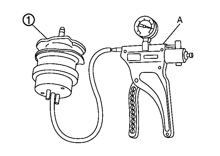
-
Check that a vacuum is maintained when applying the vacuum of −40 kPa (−0.41 kg/cm2, −5.8 psi) to electronic controlled engine mount.
-
Also visually check electronic controlled engine mount.
Is the inspection result normal?
YES>>
GO TO 8.
NO>>
Replace electronic controlled engine mount.
CHECK INTERMITTENT INCIDENT
Check intermittent incident. Refer to Intermittent Incident.
Is the inspection result normal?
YES>>
Replace intake manifold collector. Refer to Removal and Installation.
NO>>
Repair or replace error-detected parts.
Component Inspection
CHECK ELECTRONIC CONTROLLED ENGINE MOUNT CONTROL SOLENOID VALVE
 With CONSULT
-
Turn ignition switch OFF.
-
Reconnect electronic controlled engine mount control solenoid valve harness connector.
-
Disconnect vacuum hoses connected to electronic controlled engine mount control solenoid valve.
-
Turn ignition switch ON.
-
On CONSULT, select “ENGINE”>>“Active Test”>>“ENGINE MOUNTING”.
-
Check air passage continuity and operation delay time under the following conditions.
Condition
(ENGINE MOUNTING)Air passage continuity between  and
and 
Air passage continuity
between and
and 
TRVL Existed Not existed IDLE Not existed Existed
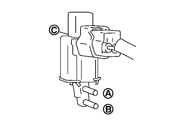
 Without CONSULT
-
Turn ignition switch OFF.
-
Disconnect electronic controlled engine mount control solenoid valve harness connector.
-
Disconnect vacuum hoses connected to electronic controlled engine mount control solenoid valve.
-
Check air passage continuity and operation delay time under the following conditions.
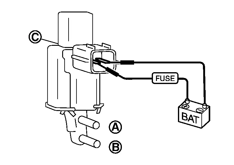
Condition Air passage continuity between  and
and 
Air passage continuity
between and
and 
12 V direct current supply between terminals 1 and 2 Existed Not existed No supply Not existed Existed
Is the inspection result normal?
YES>>
INSPECTION END
NO>>
Replace electronic controlled engine mount control solenoid valve. Refer to Component Parts Location.
Fuel Injector Nissan Pathfinder 5th Gen
Component Function Check
INSPECTION START
Turn ignition switch to START.
Are any cylinders ignited?
YES>>GO TO 2.
NO>>Proceed to Diagnosis Procedure.
CHECK FUEL INJECTOR FUNCTION
 With CONSULT
-
Start engine.
-
Perform “POWER BALANCE” in “Active Test” mode of “ENGINE”.
-
Make sure that each circuit produces a momentary engine speed drop.
 Without CONSULT
-
Start engine.
-
Listen to each fuel injector operating sound.
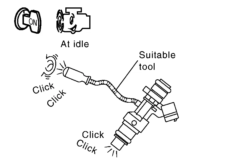
Clicking sound should be heard.
Is the inspection result normal?
YES>>INSPECTION END
NO>>Proceed to Diagnosis Procedure.
Diagnosis Procedure
CHECK FUSE
-
Turn ignition switch OFF.
-
Check that the following fuse is not blowing.
Fuse No. Capacity #92 15A #94 15A
Is the fuse blown (open)?
YES>>Replace the fuse after repairing the applicable circuit.
NO>>GO TO 2.
CHECK FUEL INJECTOR DRIVER POWER SUPPLY
-
Turn ignition switch OFF.
-
Disconnect ECM harness connector.
-
Turn ignition switch ON.
-
Check the voltage between ECM harness connector and ground.
+ − Voltage ECM Connector Terminal F78 1 Ground Battery voltage 10
Is the inspection result normal?
YES>>GO TO 9.
NO>>GO TO 3.
CHECK FUEL INJECTOR DRIVER POWER SUPPLY CIRCUIT
-
Remove fuel injector relay.
-
Check the continuity between ECM harness connector and fuel injector relay harness connector.
ECM Fuel injector relay Continuity Connector Terminal Connector Terminal F78 1 E36 10 Existed 10 14 -
Also check harness for short to ground.
Is the inspection result normal?
YES>>GO TO 4.
NO>>Repair or replace error-detected parts
CHECK FUEL INJECTOR RELAY POWER SUPPLY (CONTACTOR SIDE)
Check the voltage between fuel injector relay harness connector and ground.
| + | − | Voltage | |
|---|---|---|---|
| Fuel injector relay | |||
| Connector | Terminal | ||
| E36 | 9 | Ground | Battery voltage |
| 13 | |||
Is the inspection result normal?
YES>>GO TO 5.
NO>>Perform the trouble diagnosis for power supply circuit.
CHECK FUEL INJECTOR RELAY POWER SUPPLY (COIL SIDE)
-
Reconnect ECM harness connector.
-
Turn ignition switch ON.
-
Check the voltage between fuel injector relay harness connector and ground.
+ − Voltage Fuel injector relay Connector Terminal E36 11 Ground Battery voltage 15
Is the inspection result normal?
YES>>GO TO 7.
NO>>GO TO 6.
CHECK FUEL INJECTOR RELAY POWER SUPPLY CIRCUIT (COIL SIDE)
-
Turn ignition switch OFF.
-
Disconnect IPDM E/R harness connector.
-
Check the continuity between IPDM E/R harness connector and fuel injector harness connector.
IPDM E/R Fuel injector relay Continuity Connector Terminal Connector Terminal F24 73 E20 11 Existed 15 -
Also check harness for short to ground.
Is the inspection result normal?
YES>>Perform the trouble diagnosis for power supply circuit.
NO>>Repair or replace error-detected parts.
CHECK FUEL INJECTOR RELAY GROUND CIRCUIT
-
Turn ignition switch OFF.
-
Check the continuity between fuel injector relay harness connector and ground.
Fuel injector relay — Continuity Connector Terminal E36 12 Ground Existed 16 -
Also check harness for short to power.
Is the inspection result normal?
YES>>GO TO 8.
NO>>Repair or replace error-detected parts.
CHECK FUEL INJECTOR RELAY
Check the fuel injector relay. Refer to Component Inspection (Fuel Injector Relay).
Is the inspection result normal?
YES>>Check intermittent incident. Refer to Intermittent Incident.
NO>>Replace fuel injector relay.
CHECK ECM GROUND CIRCUIT
-
Disconnect ECM harness connectors.
-
Check the continuity between ECM harness connector and ground.
ECM — Continuity Connector Terminal F78 3 Ground Existed F79 87 E32 199 201 204 -
Also check harness for short to power.
Is the inspection result normal?
YES>>GO TO 10.
NO>>Repair or replace error-detected parts.
CHECK FUEL INJECTOR CIRCUIT
-
Turn ignition switch OFF.
-
Disconnect ECM harness connector.
-
Check the continuity between fuel injector harness connector and ECM harness connector.
Fuel injector ECM Continuity Cylinder Connector Terminal Connector Terminal 1 F352 1 F78 12 Existed 2 15 2 F302 1 17 2 14 3 F353 1 20 2 25 4 F303 1 16 2 11 5 F354 1 13 2 18 6 F304 1 21 2 24 -
Also check harness for short to power and short to ground.
Is the inspection result normal?
YES>>GO TO 11.
NO>>Repair or replace error-detected parts.
CHECK FUEL INJECTOR
Check fuel injector. Refer to Component Inspection (Fuel Injector).
Is the inspection result normal?
YES>>Check intermittent incident. Refer to Intermittent Incident.
NO>>Replace malfunctioning fuel injector. Refer to Removal and Installation.
Component Inspection (Fuel Injector)
CHECK FUEL INJECTOR
-
Turn ignition switch OFF.
-
Disconnect fuel injector harness connector.
-
Check resistance between fuel injector terminals as follows.
Fuel injector Condition Resistance Terminal 1 2 Temperature [°C (°F)] 10 – 60 (60 – 140) 1.1 – 1.9 Ω
Is the inspection result normal?
YES>>INSPECTION END
NO>>Replace malfunctioning fuel injector. Refer to Removal and Installation.
Component Inspection (Fuel Injector Relay)
CHECK FUEL INJECTOR RELAY
-
Turn ignition switch OFF.
-
Remove fuel injector relay.
-
Check the continuity between fuel injector relay terminals as per the following conditions.
Fuel injector relay Conditions Continuity No. Terminal 1 9 10 12 V direct current supply between terminals 11 and 12. Existed No current supply Not existed 2 13 14 12 V direct current supply between terminals 15 and 16. Existed No current supply Not existed
Is the inspection result normal?
YES>>INSPECTION END
NO>>Replace fuel injector relay.
Fuel Pump Nissan Pathfinder 2026
Component Function Check
CHECK FUEL PUMP FUNCTION
-
Turn ignition switch ON.
-
Pinch fuel feed hose
 with two fingers.
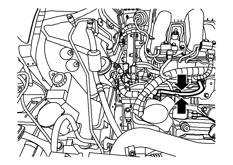
Fuel pressure pulsation should be felt on the fuel feed hose for 1 second after ignition switch is turned ON.
Is the inspection result normal?
YES>>INSPECTION END
NO>>Diagnosis Procedure.
Diagnosis Procedure
CHECK FUEL PUMP CONTROL MODULE POWER SUPPLY
-
Turn ignition switch OFF.
-
Disconnect Fuel pump control module harness connector.
-
Turn ignition switch ON.
-
Check the voltage between Fuel pump control module harness connector and ground.
+ − Voltage Fuel pump control module Connector Terminal B58 1 Ground Battery voltage
Is the inspection result normal?
YES>>GO TO 5.
NO>>GO TO 2.
CHECK FUEL PUMP CONTROL MODULE POWER SUPPLY CIRCUIT
-
Turn ignition switch OFF.
-
Disconnect IPDM E/R harness connector.
-
Check the continuity between IPDM E/R harness connector and Fuel pump control module harness connector.
IPDM E/R Fuel pump control module Continuity Connector Terminal Connector Terminal E121 46 B58 1 Existed -
Also check harness for short to power and short to ground.
Is the inspection result normal?
YES>>GO TO 3.
NO>>Repair or replace error-detected parts.
CHECK FUSE
Check that the following fuse is not blowing.
| Location | Fuse No. | Capacity |
|---|---|---|
| IPDM E/R | #85 | 20 |
Is the fuse blown (open)?
YES>>Replace the fuse after repairing the applicable circuit.
NO>>GO TO 4.
CHECK INTERMITTENT INCIDENT
Check intermittent incident. Refer to Intermittent Incident.
Is the inspection result normal?
YES>>Perform trouble diagnosis for power supply circuit.
NO>>Repair or replace error-detected parts.
CHECK FUEL PUMP CONTROL MODULE GROUND CIRCUIT
-
Turn ignition switch OFF.
-
Check the continuity between Fuel pump control module harness connector and ground.
Fuel pump control module — Continuity Connector Terminal B58 4 Ground Existed -
Also check harness for short to power.
Is the inspection result normal?
YES>>GO TO 6.
NO>>Repair or replace error-detected parts.
CHECK FUEL PUMP CONTROL MODULE INPUT AND OUTPUT CIRCUITS
-
Disconnect ECM harness connector.
-
Check the continuity between Fuel pump control module harness connector and ECM harness connector.
Fuel pump control module ECM Continuity Connector Terminal Connector Terminal B58 3 E32 182 Existed 2 188 -
Also check harness for short to power and short to ground.
Is the inspection result normal?
YES>>GO TO 7.
NO>>Repair or replace error-detected parts.
CHECK FUEL PUMP CONTROL CIRCUIT
-
Disconnect “fuel level sensor unit and fuel pump” harness connector.
-
Check the continuity between Fuel pump control module harness connector and “fuel level sensor unit and fuel pump” harness connector.
Fuel pump control module Fuel level sensor unit and fuel pump Continuity Connector Terminal Connector Terminal B58 6 B57 8 Existed 5 7
Is the inspection result normal?
YES>>GO TO 8.
NO>>Repair or replace error-detected parts.
CHECK FUEL PUMP
Check fuel pump. Refer to Component Inspection (Fuel Pump).
Is the inspection result normal?
YES>>GO TO 9.
NO>>Replace fuel level sensor, fuel filter and fuel pump assembly.Refer to Removal and Installation.
CHECK FUEL PUMP CONTROL MODULE
Check fuel pump control module. Refer to Component Inspection (Fuel Pump Control Module).
Is the inspection result normal?
YES>>Check intermittent incident. Refer to Intermittent Incident.
NO>>Replace fuel pump control module.Refer to Removal and Installation.
Component Inspection (Fuel Pump)
CHECK FUEL PUMP
-
Turn ignition switch OFF.
-
Disconnect “fuel level sensor unit and fuel pump” harness connector.
-
Check resistance between “fuel level sensor unit and fuel pump” terminals as follows.
Fuel level sensor unit and fuel pump Condition Resistance Terminal 4 6 Temperature [°C (°F)] 25 (77) 0.2 – 5.0 Ω
Is the inspection result normal?
YES>>INSPECTION END
NO>>Replace fuel level sensor, fuel filter and fuel pump assembly. Refer to Removal and Installation.
Component Inspection (Fuel Pump Control Module)
CHECK FUEL PUMP CONTROL MODULE
Check the voltage between fuel pump control module terminals under the following conditions.
| Fuel pump control module | Condition |
Voltage (Approx.) | ||
|---|---|---|---|---|
| Connector | + | − | ||
| Terminal | ||||
| B58 | 6 | 5 | For 1 second after turning ignition switch ON | 12.9 V |
| More than 1 second after turning ignition switch ON | 0 V | |||
| Idle speed | 8.1 – 12.9 V | |||
Is the inspection result normal?
YES>>INSPECTION END
NO>>Replace fuel pump control module. Refer to Removal and Installation.
High Pressure Fuel Pump Nissan Pathfinder 2022
Component Function Check
CHECK HIGH PRESSURE FUEL PUMP FUNCTION
 With CONSULT
-
Start engine.
-
On CONSULT screen, select “ENGINE”>>“Data Monitor”.
-
Check that the “FUEL PRES SEN V” indication.
Monitor Item Condition Values/Status FUEL PRES SEN V Engine speed: Idle 1.120 – 1.310 V Engine speed: Revving engine from idle to 4,000 rpm quickly 1.120 – 2.900 V
Is the inspection result normal?
YES>>INSPECTION END
NO>>Proceed to Diagnosis Procedure.
Diagnosis Procedure
CHECK HIGH PRESSURE FUEL PUMP CIRCUIT
-
Disconnect high pressure fuel pump relay harness connector.
-
Check the continuity between ECM harness connector and high pressure fuel pump harness connector.
ECM High pressure fuel pump Continuity Connector Terminal Connector Terminal F78 2 F96 2 Existed 4 1 -
Also check harness for short to ground and short to power.
Is the inspection result normal?
YES>>GO TO 2.
NO>>Repair or replace malfunctioning part.
CHECK ECM GROUND CIRCUIT
-
Turn ignition switch OFF.
-
Disconnect ECM harness connector.
-
Check the continuity between ECM harness connector and ground.
ECM — Continuity Connector Terminal F78 3 Ground Existed F79 87 E32 199 201 204 -
Also check harness for short to power.
Is the inspection result normal?
YES>>GO TO 3.
NO>>Repair or replace malfunctioning part.
CHECK HIGH PRESSURE FUEL PUMP
Refer to Component Inspection (High Pressure Fuel Pump).
Is the inspection result normal?
YES>>GO TO 4.
NO>>Replace high pressure fuel pump. Refer to Removal and Installation.
CHECK HIGH PRESSURE FUEL PUMP INSTALLATION
-
Turn ignition switch OFF.
-
Check high pressure fuel pump for improper attachment or looseness.
Is the inspection result normal?
YES>>GO TO 5.
NO>>Repair or replace malfunctioning part.
CHECK CAMSHAFT
-
Remove camshaft. Refer to Removal and Installation.
-
Check camshaft. Refer to Inspection After Removal.
Is the inspection result normal?
YES>>Check intermittent incident. Refer to Intermittent Incident.
NO>>Replace camshaft. Refer to Removal and Installation .
Component Inspection (High Pressure Fuel Pump)
CHECK HIGH PRESSURE FUEL PUMP-I
-
Turn ignition switch OFF.
-
Disconnect high pressure fuel pump harness connector.
-
Check the resistance between high pressure fuel pump terminals.
High pressure fuel pump Condition Resistance + − Terminal 1 2 Temperature °C (°F) 20 (68) 0.45 – 0.55 Ω
Is the inspection result normal?
YES>>GO TO 2.
NO>>Replace high pressure fuel pump. Refer to Removal and Installation.
CHECK HIGH PRESSURE FUEL PUMP-II
 With CONSULT
-
Reconnect high pressure fuel pump harness connector.
-
Start engine.
-
On CONSULT screen, select “ENGINE”>>“Data Monitor”.
-
Check that the “FUEL PRES SEN V” indication.
Monitor Item Condition Values/Status FUEL PRES SEN V Engine speed: Idle 1.120 – 1.310 V Engine speed: Revving engine from idle to 4,000 rpm quickly 1.120 – 2.900 V
 Without CONSULT
-
Reconnect high pressure fuel pump harness connector.
-
Start engine.
-
Check fuel rail pressure sensor signal voltage.
| ECM | Condition | Voltage | ||
|---|---|---|---|---|
| Connector | + | − | ||
| Terminal | ||||
| F78 | 47 | 85 | Engine speed: Idle | 1.12 – 1.31 V |
| Engine speed: Revving engine from idle to 4,000 rpm quickly | 1.12 – 2.90 V | |||
Is the inspection result normal?
YES>>INSPECTION END
NO>>Replace high pressure fuel pump. Refer to Removal and Installation.

Nissan Pathfinder (R53) 2022-2026 Service Manual
Dtc/circuit Diagnosis (Active Grille Shutter ... High Pressure Fuel Pump)
- Active Grille Shutter
- Ascd Indicator
- Cooling Fan
- Crankshaft Position Sensor 2
- Electrical Load Signal
- Electronic Controlled Engine Mount
- Fuel Injector
- Fuel Pump
- High Pressure Fuel Pump
Contact Us
Nissan Pathfinder Info Center
Email: info@nipathfinder.com
Phone: +1 (800) 123-4567
Address: 123 Pathfinder Blvd, Nashville, TN 37214, USA
Working Hours: Mon–Fri, 9:00 AM – 5:00 PM (EST)
