Nissan Pathfinder: Dtc/circuit Diagnosis (P0116 Engine Coolant Temperature Sensor ... P025b Fuel Pump Module a)
- P0116 Engine Coolant Temperature Sensor
- P0122 Tp Sensor
- P0127 Iat Sensor
- P0128 Thermostat Function
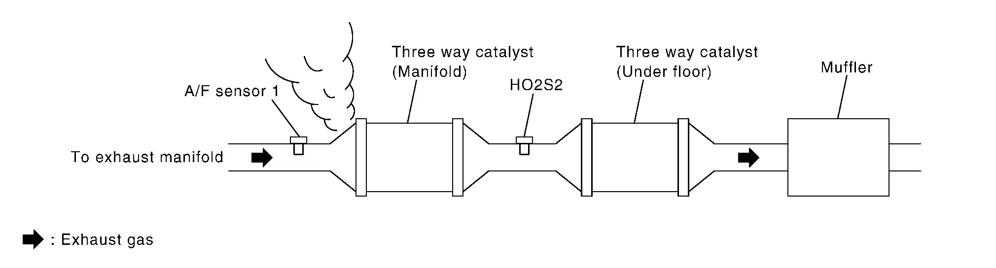
- P0130 A/f Sensor 1
- P0138 Ho2s2
- P0171 Fuel Injection System Function
- P0181 Ftt Sensor
- P01f0 Engine Coolant Temperature
- P025b Fuel Pump Module a
P0116 Engine Coolant Temperature Sensor Nissan Pathfinder R53
DTC Description
DTC DETECTION LOGIC
| DTC |
CONSULT screen terms (Trouble diagnosis content) |
DTC detection condition | |||
| P0116 | 00 |
ECT SENSOR (Engine coolant temperature sensor 1 circuit range/performance) |
A | Diagnosis condition | Engine cold start |
| Signal (terminal) | Engine coolant temperature sensor signal | ||||
| Threshold | The comparison result of signals transmitted to ECM from each temperature sensor (IAT sensor, ECT sensor, FTT sensor, and EOT sensor) shows that the voltage signal of the ECT sensor is higher/lower than that of other temperature sensors. | ||||
| Diagnosis delay time | — | ||||
| B | Diagnosis condition | — | |||
| Signal (terminal) | Engine coolant temperature sensor signal | ||||
| Threshold | Engine coolant temperature signal from engine coolant temperature sensor does not fluctuate, even when some time has passed after starting the engine with pre-warming up condition. | ||||
| Diagnosis delay time | — | ||||
POSSIBLE CAUSE
-
Harness or connectors (High or low resistance in the ECT sensor circuit)
-
ECT sensor
FAIL-SAFE
Not applicable
DTC Confirmation Procedure
CHECK DTC PRIORITY
If DTC P0116 is displayed with DTC P0117 or P0118, first perform the confirmation procedure (trouble diagnosis) for DTC P0117 or P0118.
Is DTC P0117 or P0118 detected?
YES>>Perform diagnosis of applicable.
-
DTC P0117: Refer to DTC Description.
-
DTC P0118: Refer to DTC Description.
GO TO 2.
INSPECTION START
Is it necessary to erase permanent DTC?
YES>>GO TO 4.
NO>>GO TO 3.
PERFORM COMPONENT FUNCTION CHECK
 NOTE:
NOTE:
Use the component function check to check the overall function of the ECT sensor circuit. During this check, a 1st trip DTC might not be confirmed.
-
Turn ignition switch OFF.
-
Disconnect ECT sensor harness connector.
-
Remove ECT sensor. Refer to Exploded View.
-
Check resistance between ECT sensor terminals by heating with hot water as shown in the figure.

ECT sensor Condition Resistance Terminal 1 2 Temperature [°C (°F)] 20 (68) 2.10 – 2.90 kΩ 50 (122) 0.68 – 1.00 kΩ 90 (194) 0.236 – 0.260 kΩ
Is the inspection result normal?
YES-1>>To check malfunction symptom before repair: Refer to Intermittent Incident.
YES-2>>Confirmation after repair: INSPECTION END
NO>>Proceed to Diagnosis Procedure.
PRECONDITIONING
If DTC Confirmation Procedure has been previously conducted, always perform the following procedure before conducting the next test.
-
Turn ignition switch OFF and wait at least 10 seconds.
-
Turn ignition switch ON.
-
Turn ignition switch OFF and wait at least 10 seconds.
TEST CONDITION:
-
Before performing the following procedure, do not add fuel.
-
Before performing the following procedure, check that fuel level is between 1/4 and 4/4.
-
Before performing the following procedure, confirm that battery voltage is 11 V or more at idle.
>>
GO TO 5.
PERFORM DTC CONFIRMATION PROCEDURE
-
Move the Nissan Pathfinder vehicle to a cool place.
 NOTE:
NOTE:
Cool the vehicle in an environment of ambient air temperature between −10°C (14°F) and 35°C (95°F).
-
Turn ignition switch OFF and leave the Nissan Pathfinder vehicle for 12 hours.
CAUTION:
Never turn ignition switch ON during this procedure.
 NOTE:
NOTE:
The Nissan Pathfinder vehicle must be cooled with the hood open.
-
Start engine and let it idle for 20 minutes or more.
CAUTION:
Never turn ignition switch OFF during idling.
-
Check 1st trip DTC.
Is DTC P0116 detected?
YES>>Proceed to Diagnosis Procedure.
NO-1>>To check malfunction symptom before repair: Refer to Intermittent Incident.
NO-2>>Confirmation after repair: INSPECTION END
Diagnosis Procedure
CHECK DTC PRIORITY
If DTC P0116 is displayed with DTC P0117 or P0118, first perform the confirmation procedure (trouble diagnosis) for DTC P0117 or P0118.
Is DTC P0117 or P0118 detected?
YES>>Perform diagnosis of applicable.
-
DTC P0117: Refer to DTC Description.
-
DTC P0118: Refer to DTC Description.
GO TO 2.
CHECK ENGINE COOLANT TEMPERATURE (ECT) SENSOR
Check ECT sensor. Refer to Component Inspection (Engine Coolant Temperature Sensor).
Is the inspection result normal?
YES>>INSPECTION END
NO>>Replace ECT sensor. Refer to Exploded View.
Component Inspection (Engine Coolant Temperature Sensor)
CHECK ENGINE COOLANT TEMPERATURE SENSOR
-
Turn ignition switch OFF.
-
Disconnect engine coolant temperature sensor harness connector.
-
Remove engine coolant temperature sensor. Refer to Exploded View.
-
Check resistance between engine coolant temperature sensor terminals by heating with hot water as shown in the figure.
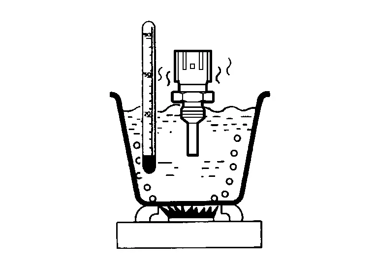
ECT sensor Condition Resistance Terminal 1 2 Temperature [°C (°F)] 20 (68) 2.10 – 2.90 kΩ 50 (122) 0.68 – 1.00 kΩ 90 (194) 0.236 – 0.260 kΩ
Is the inspection result normal?
YES>>INSPECTION END
NO>>Replace engine coolant temperature sensor. Refer to Exploded View.
P0122 Tp Sensor Nissan Pathfinder
DTC Description
DTC DETECTION LOGIC
| DTC |
CONSULT screen terms (Trouble diagnosis content) |
DTC detection condition | ||
| P0122 | 00 |
TP SEN 2/CIRC-B1 (Throttle/Pedal position sensor/switch “A” circuit low) |
Diagnosis condition | Engine running at idle |
| Signal (terminal) | Throttle position sensor 2 signal | |||
| Threshold | An excessively low voltage from the TP sensor 2 is sent to ECM | |||
| Diagnosis delay time | — | |||
POSSIBLE CAUSE
-
Harness or connectors (TP sensor 2 circuit is open or shorted.)
-
Electric throttle control actuator (TP sensor 2)
FAIL-SAFE
| Fail safe mode | Nissan Pathfinder Vehicle behavior | |
|---|---|---|
| Device fix mode |
|
|
DTC Confirmation Procedure
CHECK DTC PRIORITY
If DTC P0122 is displayed with DTC P0643, first perform the confirmation procedure (trouble diagnosis) for DTC P0643.
Is DTC P0643 detected?
YES>>
Perform diagnosis of applicable. Refer to DTC Description.
NO>>
GO TO 2.
PRECONDITIONING
If DTC Confirmation Procedure has been previously conducted, always perform the following procedure before conducting the next test.
-
Turn ignition switch OFF and wait at least 10 seconds.
-
Turn ignition switch ON.
-
Turn ignition switch OFF and wait at least 10 seconds.
TESTING CONDITION:
Before performing the following procedure, confirm that battery voltage is more than 10 V at idle.
>>
GO TO 3.
PERFORM DTC CONFIRMATION PROCEDURE
-
Start engine and let it idle for 1 second.
-
Check DTC.
Is DTC P0122 detected?
YES>>
Proceed to Diagnosis Procedure.
NO-1>>
To check malfunction symptom before repair: Refer to Intermittent Incident.
NO-1>>
Confirmation after repair: INSPECTION END
Diagnosis Procedure
CHECK DTC PRIORITY
If DTC P0122 is displayed with DTC P0643, first perform the confirmation procedure (trouble diagnosis) for DTC P0643.
Is DTC P0643 detected?
YES>>
Perform diagnosis of applicable. Refer to DTC Description.
NO>>
GO TO 2.
CHECK THROTTLE POSITION SENSOR 2 POWER SUPPLY
-
Disconnect electric throttle control actuator harness connector.
-
Turn ignition switch ON.
-
Check the voltage between electric throttle control actuator harness connector and ground.
+ − Voltage
(Approx.)Electric throttle control actuator Connector Terminal F50 5 Ground 5 V
Is the inspection result normal?
YES>>
GO TO 4.
NO>>
GO TO 3.
CHECK THROTTLE POSITION SENSOR 2 POWER SUPPLY CIRCUIT
-
Turn ignition switch OFF.
-
Disconnect ECM harness connector.
-
Check the continuity between electric throttle control actuator harness connector and ECM harness connector.
Electric throttle control actuator ECM Continuity Connector Terminal Connector Terminal F50 5 F79 129 Existed -
Also check harness for short to power and short to ground.
Is the inspection result normal?
YES>>
Perform the trouble diagnosis for ECM power supply circuit. Refer to Diagnosis Procedure.
NO>>
Repair or replace error-detected parts.
CHECK THROTTLE POSITION SENSOR 2 GROUND CIRCUIT
-
Turn ignition switch OFF.
-
Disconnect ECM harness connector.
-
Check the continuity between electric throttle control actuator harness connector and ECM harness connector.
Electric throttle control actuator ECM Continuity Connector Terminal Connector Terminal F50 4 F79 100 Existed -
Also check harness for short to power.
Is the inspection result normal?
YES>>
GO TO 5.
NO>>
Repair or replace error-detected parts.
CHECK ECM GROUND CIRCUIT
-
Check the continuity between ECM harness connector and ground.
ECM — Continuity Connector Terminal F78 3 Ground Existed F79 87 E32 199 201 204 -
Also check harness for short to power.
Is the inspection result normal?
YES>>
GO TO 6.
NO>>
Repair or replace error-detected parts.
CHECK THROTTLE POSITION SENSOR 2 INPUT SIGNAL CIRCUIT
-
Check the continuity between electric throttle control actuator harness connector and ECM harness connector.
Electric throttle control actuator ECM Continuity Connector Terminal Connector Terminal F50 3 F79 114 Existed -
Also check harness for short to power and short to ground.
Is the inspection result normal?
YES>>
GO TO 7.
NO>>
Repair or replace error-detected parts.
CHECK THROTTLE POSITION SENSOR
Refer to Component Inspection (Throttle Position Sensor).
Is the inspection result normal?
YES>>
INSPECTION END
NO>>
Replace malfunctioning electric throttle control actuator. Refer to Exploded View.
Component Inspection (Throttle Position Sensor)
CHECK THROTTLE POSITION SENSOR
-
Turn ignition switch OFF.
-
Reconnect all harness connectors disconnected.
-
Perform Description.
-
Turn ignition switch ON.
-
Set selector lever to D position.
-
Check the voltage between ECM harness connector terminals under the following conditions.
ECM Condition Voltage Connector Terminal F79 103 (TP sensor 1) 100 Accelerator pedal Fully released More than 0.36 V Fully depressed Less than 4.75 V 114 (TP sensor 2) Fully released Less than 4.75 V Fully depressed More than 0.36 V
Is the inspection result normal?
YES>>
INSPECTION END
NO>>
GO TO 2.
REPLACE ELECTRIC THROTTLE CONTROL ACTUATOR
-
Replace malfunctioning electric throttle control actuator.
-
Proceed to Description.
>>
INSPECTION END
P0127 Iat Sensor Nissan Pathfinder 5th Gen
DTC Description
DTC DETECTION LOGIC
| DTC |
CONSULT screen terms (Trouble diagnosis content) |
DTC detection condition | ||
| P0127 | 00 |
IAT SENSOR-B1 (Intake air temperature too high) |
Diagnosis condition | — |
| Signal (terminal) | Intake air temperature sensor signal | |||
| Threshold | When the amount of intake air is sufficient, the temperature sent from IAT sensor is more than 90°C (194°F) | |||
| Diagnosis delay time | — | |||
POSSIBLE CAUSE
-
Harness or connectors (Intake air temperature sensor circuit is open or shorted)
-
Intake air temperature sensor
FAIL-SAFE
Not applicable
DTC Confirmation Procedure
PRECONDITIONING
If DTC Confirmation Procedure has been previously conducted, always perform the following procedure before conducting the next test.
-
Turn ignition switch OFF and wait at least 10 seconds.
-
Turn ignition switch ON.
-
Turn ignition switch OFF and wait at least 10 seconds.
TESTING CONDITION:
This test may be conducted with the drive wheels lifted in the shop or by driving the Nissan Pathfinder vehicle. If a road test is expected to be easier, it is unnecessary to lift the vehicle.
>>
GO TO 2.
PERFORM DTC CONFIRMATION PROCEDURE
 With CONSULT
-
Wait until engine coolant temperature is less than 96°C (205°F)
-
Turn ignition switch ON.
-
On CONSULT screen, select “ENGINE”>>“Data Monitor”.
-
Check the engine coolant temperature.
-
If the engine coolant temperature is not less than 96°C (205°F), turn ignition switch OFF and cool down engine.
 NOTE:
NOTE:
Perform the following steps before engine coolant temperature is above 96°C (205°F).
-
-
Turn ignition switch ON.
-
On CONSULT screen, select “ENGINE”>>“Data Monitor”.
-
Start engine.
-
Hold Nissan Pathfinder vehicle speed at more than 70 km/h (44 MPH) for 100 consecutive seconds.
CAUTION:
Always drive Nissan Pathfinder vehicle at a safe speed.
-
Check 1st trip DTC.
Is DTC P0127 detected?
YES>>Proceed to Diagnosis Procedure.
NO-1>>To check malfunction symptom before repair: Refer to Intermittent Incident.
NO-2>>Confirmation after repair: INSPECTION END
Diagnosis Procedure
CHECK INTAKE AIR TEMPERATURE SENSOR
Refer to Component Inspection (Intake Air Temperature Sensor).
Is the inspection result normal?
YES>>INSPECTION END
NO>>Replace mass air flow sensor (with intake air temperature sensor). Refer to Exploded View.
Component Inspection (Intake Air Temperature Sensor)
CHECK INTAKE AIR TEMPERATURE SENSOR
 With CONSULT
-
Turn ignition switch OFF.
-
Disconnect mass air flow (MAF) sensor (intake air temperature sensor is built-into) harness connector and reconnect it.
-
Turn ignition switch ON.
-
On CONSULT screen, select “ENGINE”>>“Data Monitor”>>“INT/A TEMP SEN”.
-
Check that the indicated value of “INT/A TEMP SEN” is almost the same as intake air temperature.
Is the inspection result normal?
YES>>INSPECTION END
NO>>Replace mass air flow sensor (with intake air temperature sensor). Refer to Exploded View.
P0128 Thermostat Function Nissan Pathfinder 2022
DTC Description
Engine coolant temperature has not risen enough to open the thermostat even though the engine has run long enough.
This is due to a leak in the seal or the thermostat being stuck open.
DTC DETECTION LOGIC
| DTC |
CONSULT screen terms (Trouble diagnosis content) |
DTC detection condition | ||
| P0128 | 00 |
THERMSTAT FNCTN [Coolant thermostat (coolant temperature below thermostat regulating temperature)] |
Diagnosis condition | — |
| Signal (terminal) | Engine coolant temperature sensor signal | |||
| Threshold | The engine coolant temperature does not reach to specified temperature even though the engine has run long enough. | |||
| Diagnosis delay time | — | |||
POSSIBLE CAUSE
-
Thermostat
-
Leakage from sealing portion of thermostat
-
Engine coolant temperature sensor
FAIL-SAFE
Not applicable
DTC Confirmation Procedure
 NOTE:
NOTE:
Never refuel before and during the following procedure.
CHECK DTC PRIORITY
If DTC P0128 is displayed with DTC P0300, P0301, P0302, P0303, P0304, P0305 or P0306, first perform the confirmation procedure (trouble diagnosis) for DTC P0300, P0301, P0302, P0303, P0304, P0305 or P0306.
Is DTC P0300, P0301, P0302, P0303, P0304, P0305 or P0306 detected?
YES>>Perform diagnosis of applicable. Refer to DTC Index.
NO>>GO TO 2.
PRECONDITIONING-I
If DTC Confirmation Procedure has been previously conducted, always perform the following procedure before conducting the next test.
-
Turn ignition switch OFF and wait at least 10 seconds.
-
Turn ignition switch ON.
-
Turn ignition switch OFF and wait at least 10 seconds.
>>
GO TO 3.
PRECONDITIONING-II
 With CONSULT
-
Turn ignition switch ON.
-
Check the following conditions:
Ambient temperature −10°C (14°F) or more A/C switch OFF Blower fan switch OFF -
On CONSULT screen, select “ENGINE”>>“Data Monitor”>>“COOLANT TEMP/S”.
-
Check the following conditions:
COOLANT TEMP/S −10°C – 55°C (14 – 131°F)
Is the condition satisfied?
YES>>GO TO 4.
NO>>-
Satisfy the condition.
-
GO TO 4.
PERFORM DTC CONFIRMATION PROCEDURE-I
 With CONSULT
-
Start engine.
-
Drive the Nissan Pathfinder vehicle until the following condition is satisfied.
CAUTION:
Always drive vehicle at safe speed.
-
STEP 1
Drive the Nissan Pathfinder vehicle under the conditions instructed below until the difference between “COOLANT TEMP/S” and “FUEL T/TMP SE” becomes at least 25°C (45°F).
COOLANT TEMP/S 74°C (165°F) or less FUEL T/TMP SE Less than the value calculated by subtracting 25°C (45°F) from “COOLANT TEMP/S”.* *: Example COOLANT TEMP/S FUEL T/TMP SE 70°C (158°F) 45°C (113°F) or less 65°C (149°F) 40°C (104°F) or less 60°C (140°F) 35°C (95°F) or less -
STEP 2
Drive the Nissan Pathfinder vehicle at 50 km/h (32 MPH) or more with the difference between “COOLANT TEMP/S” and “FUEL T/TMP SE” maintained at 25°C (45°F) or more.
 NOTE:
NOTE:
Keep the accelerator pedal as steady as possible during cruising.
-
STEP 3
Drive the Nissan Pathfinder vehicle at 50 km/h (32 MPH) or more until “COOLANT TEMP/S” increases by 6°C (43°F).
 NOTE:
NOTE:
Keep the accelerator pedal as steady as possible during cruising.
-
Is the condition satisfied?
YES>>GO TO 5.
NO>>GO TO 2.
PERFORM DTC CONFIRMATION PROCEDURE-II
 With CONSULT
-
Drive the Nissan Pathfinder vehicle until the following condition is satisfied.
COOLANT TEMP/S 71°C (160°F) or more CAUTION:
Always drive Nissan Pathfinder vehicle at safe speed.
-
Check 1st trip DTC.
Is DTC P0128 detected?
YES>>Proceed to Diagnosis Procedure.
NO-1>>To check malfunction symptom before repair: Refer to Intermittent Incident.
NO-2>>Confirmation after repair: INSPECTION END
Diagnosis Procedure
CHECK DTC PRIORITY
If DTC P0128 is displayed with DTC P0300, P0301, P0302, P0303, P0304, P0305 or P0306, first perform the confirmation procedure (trouble diagnosis) for DTC P0300, P0301, P0302, P0303, P0304, P0305 or P0306.
Is DTC P0300, P0301, P0302, P0303, P0304, P0305 or P0306 detected?
YES>>Perform diagnosis of applicable. Refer to DTC Index.
NO>>GO TO 2.
CHECK ENGINE COOLANT TEMPERATURE SENSOR
Check engine coolant temperature sensor. Refer to Component Inspection (Engine Coolant Temperature Sensor).
Is the inspection result normal?
YES>>GO TO 3.
NO>>Replace engine coolant temperature sensor.
CHECK THERMOSTAT
Check thermostat. Refer to Removal and Installation.
Is the inspection result normal?
YES>>INSPECTION END
NO>>Replace thermostat. Refer to Removal and Installation.
P0130 A/f Sensor 1 Nissan Pathfinder 2026
DTC Description
To judge malfunctions, the diagnosis checks that the A/F signal computed by ECM from the A/F sensor 1 signal fluctuates according to fuel feedback control.
DTC DETECTION LOGIC
| DTC |
CONSULT screen terms (Trouble diagnosis content) |
DTC detection condition | |||
| P0130 | 00 |
A/F SENSOR1 (B1) [Air fuel ratio (A/F) sensor 1 (bank 1) circuit] |
A | Diagnosis condition | — |
| Signal (terminal) | A/F sensor 1 (bank 1) signal | ||||
| Threshold | The A/F signal computed by ECM from the A/F sensor 1 signal is constantly in a range other than approx. 2.2 V | ||||
| Diagnosis delay time | — | ||||
| B | Diagnosis condition | — | |||
| Signal (terminal) | A/F sensor 1 (bank 1) signal | ||||
| Threshold | The A/F signal computed by ECM from the A/F sensor 1 signal is constantly approx. 2.2 V | ||||
| Diagnosis delay time | — | ||||
POSSIBLE CAUSE
-
Harness or connectors [The A/F sensor 1 (bank 1) circuit is open or shorted.]
-
A/F sensor 1 (bank 1)
FAIL-SAFE
Not applicable
DTC Confirmation Procedure
PRECONDITIONING
If DTC Confirmation Procedure has been previously conducted, always perform the following procedure before conducting the next test.
-
Turn ignition switch OFF and wait at least 10 seconds.
-
Turn ignition switch ON.
-
Turn ignition switch OFF and wait at least 10 seconds.
TESTING CONDITION:
Before performing the following procedure, confirm that battery voltage is more than 11 V at idle.
>>
GO TO 2.
PERFORM DTC CONFIRMATION PROCEDURE FOR MALFUNCTION A
-
Start engine and warm it up to normal operating temperature.
-
Let engine idle for 2 minutes.
-
Check 1st trip DTC.
Is DTC P0130 detected?
YES>>
Proceed to Diagnosis Procedure.
NO-1>>
With CONSULT: GO TO 3.
NO-2>>
Without CONSULT: GO TO 7 .
CHECK AIR FUEL RATIO (A/F) SENSOR 1 FUNCTION
 With CONSULT
-
Start engine and warm it up to normal operating temperature.
-
On CONSULT screen, select “ENGINE”>>“Data Monitor”>>“A/F SEN1 (B1)” or “A/F SEN1 (B2)”.
-
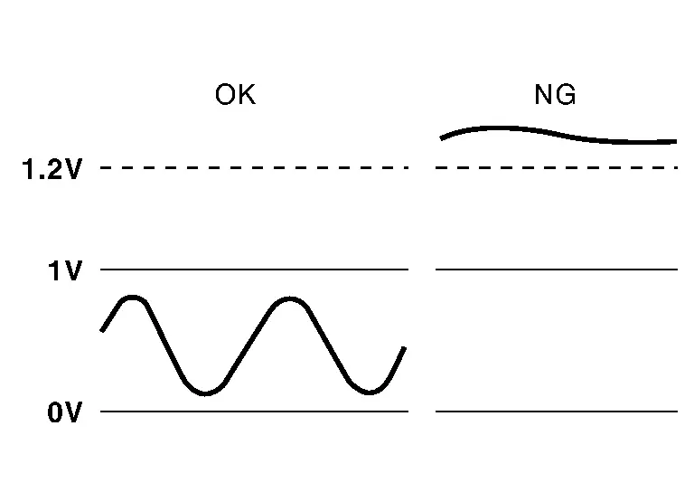
Check “A/F SEN1 (B1)” or “A/F SEN1 (B2)” indication.
Does the indication fluctuate around 2.2 V?
YES>>
GO TO 4.
NO>>
Proceed to Diagnosis Procedure.
PERFORM DTC CONFIRMATION PROCEDURE FOR MALFUNCTION B-I
 With CONSULT
-
On CONSULT screen, select “ENGINE”>>“DTC Work Support”>>“A/F SEN1”>>“A/F SEN1 (B1) P1276” (for DTC P0130) or “A/F SEN1 (B2) P1286” (for DTC P0150).
-
Touch “START”.
-
When the following conditions are met, “TESTING” will be displayed on the CONSULT screen.
ENG SPEED 1,000 – 3,200 rpm VHCL SPEED SE More than 64 km/h (40 mph) B/FUEL SCHDL 1.0 – 10.0 msec Selector lever D position If “TESTING” is not displayed after 20 seconds, retry from step 2.
CAUTION:
Always drive Nissan Pathfinder vehicle at a safe speed.
Is “TESTING” displayed on CONSULT screen?
YES>>
GO TO 5.
NO>>
Check A/F sensor 1 function again. GO TO 3.
PERFORM DTC CONFIRMATION PROCEDURE FOR MALFUNCTION B-II
Release accelerator pedal fully.
 NOTE:
NOTE:
Never apply brake when releasing the accelerator pedal.
Which does “TESTING” change to?
COMPLETED>>
GO TO 6.
OUT OF CONDITION>>
Retry DTC CONFIRMATION PROCEDURE. GO TO 4.
PERFORM DTC CONFIRMATION PROCEDURE FOR MALFUNCTION B-III
Touch “SELF-DIAG RESULT”.
Is “OK” displayed on CONSULT screen?
YES-1>>
To check malfunction symptom before repair: Refer to Intermittent Incident.
YES-2>>
Confirmation after repair: INSPECTION END
NO>>
Proceed to Diagnosis Procedure.
PERFORM COMPONENT FUNCTION CHECK FOR MALFUNCTION B
 NOTE:
NOTE:
Use component function check to check the overall function of the A/F sensor 1 circuit. During this check, a 1st trip DTC might not be confirmed.
 With GST
-
Start engine and warm it up to normal operating temperature.
-
Drive the Nissan Pathfinder vehicle at a speed of 80 km/h (50 MPH) for a few minutes in the suitable gear position.
-
Shift the selector lever to D position, then release the accelerator pedal fully until the Nissan Pathfinder vehicle speed decreases to 50 km/h (30 MPH).
CAUTION:
Always drive vehicle at a safe speed.
 NOTE:
NOTE: Never apply brake when releasing the accelerator pedal.
-
Repeat steps 2 and 3 for five times.
-
Stop the Nissan Pathfinder vehicle and turn ignition switch OFF.
-
Turn ignition switch ON.
-
Turn ignition switch OFF and wait at least 10 seconds.
-
Restart engine.
-
Repeat steps 2 and 3 for five times.
-
Stop the Nissan Pathfinder vehicle and connect GST to the vehicle.
-
Check 1st trip DTC.
Is DTC P0130 or P0150 detected?
YES>>
Proceed to Diagnosis Procedure.
NO-1>>
To check malfunction symptom before repair: Refer to Intermittent Incident.
NO-2>>
Confirmation after repair: INSPECTION END
Diagnosis Procedure
CHECK GROUND CONNECTION
-
Turn ignition switch OFF.
-
Check ground connection E9. Refer to Ground Inspection in Circuit Inspection.
Is the inspection result normal?
YES>>
GO TO 2.
NO>>
Repair or replace ground connection.
CHECK AIR FUEL RATIO (A/F) SENSOR 1 POWER SUPPLY
-
Disconnect A/F sensor 1 harness connector.
-
Turn ignition switch ON.
-
Check the voltage between A/F sensor 1 harness connector and ground.
+ − Voltage A/F sensor 1 Bank Connector Terminal 1 F72 1 Ground Battery voltage
Is the inspection result normal?
YES>>
GO TO 4.
NO>>
GO TO 3.
CHECK A/F SENSOR 1 POWER SUPPLY CIRCUIT
-
Turn ignition switch OFF.
-
Disconnect IPDM E/R harness connector.
-
Check the continuity between IPDM E/R harness connector and A/F sensor 1 harness connector.
IPDM E/R A/F sensor 1 Continuity Connector Terminal Connector Terminal F24 75 F72 1 Existed -
Also check harness for short to ground.
Is the inspection result normal?
YES>>
Perform the trouble diagnosis for power supply circuit.
NO>>
Repair or replace error-detected parts.
CHECK A/F SENSOR 1 INPUT SIGNAL CIRCUIT
-
Turn ignition switch OFF.
-
Disconnect ECM harness connector.
-
Check the continuity between A/F sensor 1 harness connector and ECM harness connector.
A/F sensor 1 ECM Continuity Bank Connector Terminal Connector Terminal 1 F72 3 F79 102 Existed 4 101 -
Check the continuity between A/F sensor 1 harness connector and ground, or ECM harness connector and ground.
A/F sensor 1 — Continuity Bank Connector Terminal 1 F72 3 Ground Not existed 4 ECM — Continuity Bank Connector Terminal 1 F79 102 Ground Not existed 101 -
Also check harness for short to power.
Is the inspection result normal?
YES>>
Replace malfunctioning air fuel ratio (A/F) sensor 1. Refer to Exploded View.
NO>>
Repair open circuit, short to ground or short to power in harness or connectors.
P0138 Ho2s2 Nissan Pathfinder R53
DTC Description
The heated oxygen sensor 2 has a much longer switching time between rich and lean than the air fuel ratio (A/F) sensor 1. The oxygen storage capacity of the three way catalyst 1 causes the longer switching time.
MALFUNCTION A
To judge malfunctions of heated oxygen sensor 2, ECM monitors whether the voltage is unusually high during various driving conditions such as fuel cut.
MALFUNCTION B
To judge malfunctions of heated oxygen sensor 2, ECM monitors whether the minimum voltage of sensor is sufficiently low during various driving conditions such as fuel cut.
DTC DETECTION LOGIC
| DTC |
CONSULT screen terms (Trouble diagnosis content) |
DTC detection condition | |||
| P0138 | 00 |
HO2S2 (B1) (O2 sensor circuit high voltage bank 1 sensor 2) |
A | Diagnosis condition | — |
| Signal (terminal) | Heated oxygen sensor 2 (bank 1) signal | ||||
| Threshold | An excessively high voltage from the sensor is sent to ECM | ||||
| Diagnosis delay time | — | ||||
| B | Diagnosis condition | — | |||
| Signal (terminal) | Heated oxygen sensor 2 (bank 1) signal | ||||
| Threshold | The minimum voltage from the sensor is not reached to the specified voltage | ||||
| Diagnosis delay time | — | ||||
POSSIBLE CAUSE
DTC P0138 - A
-
Harness or connectors [The heated oxygen sensor 2 (bank 1) circuit is open or shorted.]
-
Heated oxygen sensor 2 (bank 1)
DTC P0138 - B
-
Harness or connectors [The heated oxygen sensor 2 (bank 1) circuit is open or shorted.]
-
Heated oxygen sensor 2 (bank 1)
-
Fuel pressure
-
Fuel injector
FAIL-SAFE
Not applicable
DTC Confirmation Procedure
PRECONDITIONING
If DTC Confirmation Procedure has been previously conducted, always perform the following procedure before conducting the next test.
-
Turn ignition switch OFF and wait at least 10 seconds.
-
Turn ignition switch ON.
-
Turn ignition switch OFF and wait at least 10 seconds.
>>
GO TO 2.
PERFORM DTC CONFIRMATION PROCEDURE FOR MALFUNCTION A
-
Start engine and warm it up to the normal operating temperature.
-
Turn ignition switch OFF and wait at least 10 seconds.
-
Turn ignition switch ON.
-
Turn ignition switch OFF and wait at least 10 seconds.
-
Start engine and keep the engine speed between 3,500 and 4,000 rpm for at least 1 minute under no load.
-
Let engine idle for 2 minutes.
-
Check 1st trip DTC.
Is DTC P0138 detected?
YES>>Proceed to Diagnosis Procedure.
NO-1>>With CONSULT: GO TO 3.
NO-2>>Without CONSULT: GO TO 5.
PERFORM DTC CONFIRMATION PROCEDURE FOR MALFUNCTION B
 NOTE:
NOTE:
For better results, perform “DTC WORK SUPPORT” at a temperature of 0 to 30 °C (32 to 86 °F).
 With CONSULT
-
Turn ignition ON.
-
On CONSULT screen, select “ENGINE”>>“Data Monitor”
-
Start engine and warm it up to the normal operating temperature.
-
Turn ignition switch OFF and wait at least 10 seconds.
-
Turn ignition switch ON.
-
Turn ignition switch OFF and wait at least 10 seconds.
-
Start engine and keep the engine speed between 3,500 and 4,000 rpm for at least 1 minute under no load.
-
Let engine idle for 1 minute.
-
Make sure that “COOLAN TEMP/S” indicates more than 70°C (158°F).
If not, warm up engine and go to next step when “COOLAN TEMP/S” indication reaches 70°C (158°F).
-
Open engine hood.
-
On CONSULT screen, select “ENGINE”>>“DTC Work Support”>>“HO2S2”>>“HO2S2 (B1) P1146” (for DTC P0138) or “HO2S2 (B2) P1166” (for DTC P0158).
-
Start engine and follow the instruction of CONSULT display.
 NOTE:
NOTE:
It will take at most 10 minutes until “COMPLETED” is displayed.
-
Touch “SELF-DIAG RESULTS”.
Is “OK” displayed on CONSULT screen?
YES-1>>To check malfunction symptom before repair: Refer to Intermittent Incident.
YES-2>>Confirmation after repair: INSPECTION END
NO>>Proceed to Diagnosis Procedure.
CON NOT BE DIAGNOSED>>GO TO 4.
PERFORM DTC CONFIRMATION PROCEDURE FOR MALFUNCTION B AGAIN
-
Turn ignition switch OFF and leave the Nissan Pathfinder vehicle in a cool place (soak the vehicle).
-
Perform DTC confirmation procedure again.
>>
GO TO 3.
PERFORM COMPONENT FUNCTION CHECK FOR MALFUNCTION-1
 NOTE:
NOTE:
Use component function check to check the overall function of the heated oxygen sensor 2 circuit. During this check, a 1st trip DTC might not be confirmed.
 Without CONSULT
-
Start engine and warm it up to the normal operating temperature.
-
Turn ignition switch OFF and wait at least 10 seconds.
-
Start engine and keep the engine speed between 3,500 and 4,000 rpm for at least 1 minute under no load.
-
Let engine idle for 1 minute.
-
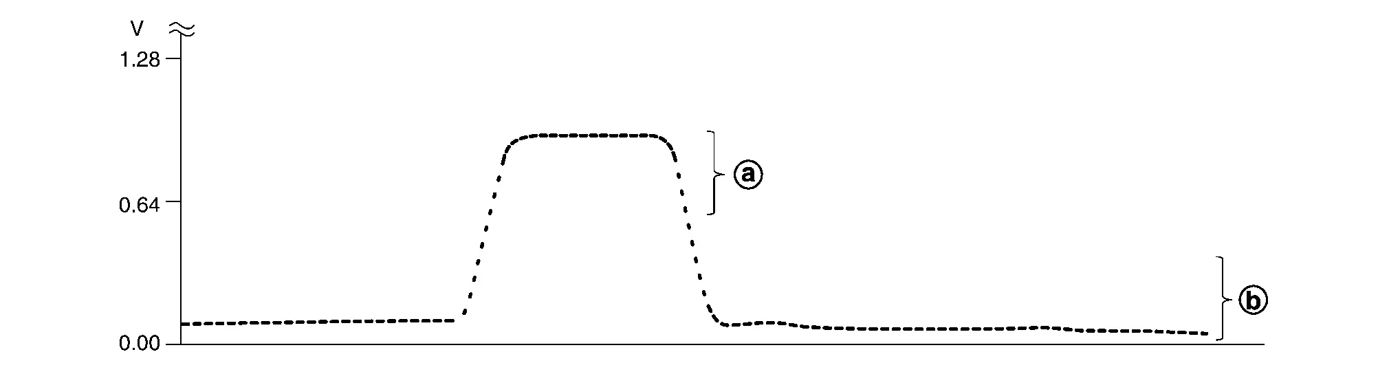
Check the voltage between ECM harness connector terminals under the following condition.
ECM Condition Voltage Connector + − Terminal F78 49 81 Revving up to 4,000 rpm under no load at least 10 times The voltage should be below 0.27 V at least once during this procedure.
Is the inspection result normal?
YES-1>>To check malfunction symptom before repair: Refer to Intermittent Incident.
YES-2>>Confirmation after repair: INSPECTION END
NO>>GO TO 6.
PERFORM COMPONENT FUNCTION CHECK FOR MALFUNCTION-2
Check the voltage between ECM harness connector terminals under the following condition.
| ECM | Condition | Voltage | ||
|---|---|---|---|---|
| Connector | + | − | ||
| Terminal | ||||
| F78 | 49 | 81 | Keeping engine at idle for 10 minutes | The voltage should be below 0.27 V at least once during this procedure. |
Is the inspection result normal?
YES-1>>To check malfunction symptom before repair: Refer to Intermittent Incident.
YES-2>>Confirmation after repair: INSPECTION END
NO>>GO TO 7.
PERFORM COMPONENT FUNCTION CHECK FOR MALFUNCTION-3
Check the voltage between ECM harness connector terminals under the following condition.
| ECM | Condition | Voltage | ||
|---|---|---|---|---|
| Connector | + | − | ||
| Terminal | ||||
| F78 | 49 | 81 | Coasting from 80 km/h (50 MPH) in D position | The voltage should be below 0.27 V at least once during this procedure. |
Is the inspection result normal?
YES-1>>To check malfunction symptom before repair: Refer to Intermittent Incident.
YES-2>>Confirmation after repair: INSPECTION END
NO>>Proceed to Diagnosis Procedure.
Diagnosis Procedure
INSPECTION START
Confirm the detected malfunction (A or B). Refer to DTC Description.
Which malfunction is detected?
A>>GO TO 2
B>>GO TO 7.
CHECK GROUND CONNECTION
-
Turn ignition switch OFF.
-
Check ground connection E9. Refer to Ground Inspection in Circuit Inspection.
Is the inspection result normal?
YES>>GO TO 3.
NO>>Repair or replace ground connection.
CHECK HO2S2 GROUND CIRCUIT
-
Disconnect heated oxygen sensor 2 (HO2S2) harness connector.
-
Disconnect ECM harness connector.
-
Check the continuity between HO2S2 harness connector and ECM harness connector.
HO2S2 ECM Continuity Bank Connector Terminal Connector Terminal 1 F71 4 F78 81 Existed -
Also check harness for short to power.
Is the inspection result normal?
YES>>GO TO 4.
NO>>Repair open circuit, short to ground or short to power in harness or connectors.
CHECK HO2S2 INPUT SIGNAL CIRCUIT
-
Check the continuity between HO2S2 harness connector and ECM harness connector.
HO2S2 ECM Continuity Bank Connector Terminal Connector Terminal 1 F71 3 F78 49 Existed -
Check the continuity between HO2S2 harness connector and ground, or ECM harness connector and ground.
HO2S2 — Continuity Bank Connector Terminal 1 F71 3 Ground Not existed ECM — Continuity Bank Connector Terminal 1 F78 49 Ground Not existed -
Also check harness for short to power.
Is the inspection result normal?
YES>>GO TO 5.
NO>>Repair open circuit, short to ground or short to power in harness or connectors.
CHECK HO2S2 CONNECTOR FOR WATER
Check connectors for water.
| Water should not exist. |
Is the inspection result normal?
YES>>GO TO 6.
NO>>Repair or replace harness or connectors.
CHECK HEATED OXYGEN SENSOR 2
Refer to Component Inspection.
Is the inspection result normal?
YES>>INSPECTION END
NO>>Replace malfunctioning heated oxygen sensor 2. Refer to Exploded View.
CHECK GROUND CONNECTION
-
Turn ignition switch OFF.
-
Check ground connection E9. Refer to Ground Inspection in Circuit Inspection.
Is the inspection result normal?
YES>>GO TO 8.
NO>>Repair or replace ground connection.
CLEAR THE MIXTURE RATIO SELF-LEARNING VALUE
-
Clear the mixture ratio self-learning value. Refer to Description.
-
Run engine for at least 10 minutes at idle speed.
Is the 1st trip DTC P0172 or P0175 detected? Is it difficult to start engine?
YES>>Perform trouble diagnosis for DTC P0172, P0175. Refer to DTC Description.
NO>>GO TO 9.
CHECK HO2S2 GROUND CIRCUIT
-
Turn ignition switch OFF.
-
Disconnect heated oxygen sensor 2 harness connector.
-
Disconnect ECM harness connector.
-
Check the continuity between HO2S2 harness connector and ECM harness connector.
HO2S2 ECM Continuity Bank Connector Terminal Connector Terminal 1 F71 4 F78 81 Existed -
Also check harness for short to power.
Is the inspection result normal?
YES>>GO TO 10.
NO>>Repair open circuit, short to ground or short to power in harness or connectors.
CHECK HO2S2 INPUT SIGNAL CIRCUIT
-
Check the continuity between HO2S2 harness connector and ECM harness connector.
HO2S2 ECM Continuity Bank Connector Terminal Connector Terminal 1 F71 3 F78 49 Existed -
Check the continuity between HO2S2 harness connector or ECM harness connector and ground.
HO2S2 — Continuity Bank Connector Terminal 1 F71 3 Ground Not existed ECM — Continuity Bank Connector Terminal 1 F78 49 Ground Not existed -
Also check harness for short to power.
Is the inspection result normal?
YES>>GO TO 11.
NO>>Repair open circuit, short to ground or short to power in harness or connectors.
CHECK HEATED OXYGEN SENSOR 2
Refer to Component Inspection.
Is the inspection result normal?
YES>>INSPECTION END
NO>>Replace malfunctioning heated oxygen sensor 2. Refer to Exploded View.
Component Inspection
INSPECTION START
Do you have CONSULT?
YES>>GO TO 2.
NO>>GO TO 3.
CHECK HEATED OXYGEN SENSOR 2
 With CONSULT
-
Turn ignition switch ON.
-
On CONSULT screen, select “ENGINE”>>“Data Monitor”.
-
Start engine and warm it up to the normal operating temperature.
-
Turn ignition switch OFF and wait at least 10 seconds.
-
Start engine and keep the engine speed between 3,500 and 4,000 rpm for at least 1 minute under no load.
-
Let engine idle for 1 minute.
-
On CONSULT screen, select “ENGINE”>>“Active Test”>>“FUEL INJECTION”
-
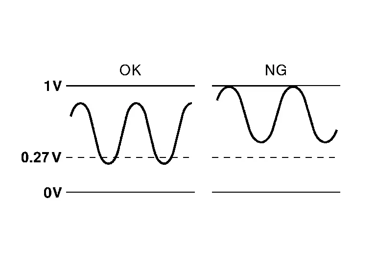
Check “HO2S2 (B1)/(B2)” at idle speed when adjusting “FUEL INJECTION” to ±25%.
“HO2S2 (B1)/(B2)” should be above
 0.72 V at least once when the “FUEL INJECTION” is +25%.
“HO2S2 (B1)/(B2)” should be below
 0.27 V at least once when the “FUEL INJECTION” is −25%.
Is the inspection result normal?
YES>>INSPECTION END
NO>>Replace malfunctioning heated oxygen sensor 2. Refer to Exploded View.
CHECK HEATED OXYGEN SENSOR 2-I
 Without CONSULT
-
Start engine and warm it up to the normal operating temperature.
-
Turn ignition switch OFF and wait at least 10 seconds.
-
Start engine and keep the engine speed between 3,500 and 4,000 rpm for at least 1 minute under no load.
-
Let engine idle for 1 minute.
-
Check the voltage between ECM harness connector terminals under the following condition.
ECM Condition Voltage Connector + – Terminal F78 49
[HO2S2 (bank 1)]81 Revving up to 4,000 rpm under no load at least 10 times The voltage should be above 0.72 V at least once during this procedure.
The voltage should be below 0.27 V at least once during this procedure.
Is the inspection result normal?
YES>>INSPECTION END
NO>>GO TO 4.
CHECK HEATED OXYGEN SENSOR 2-II
Check the voltage between ECM harness connector terminals under the following condition.
| ECM | Condition | Voltage | ||
|---|---|---|---|---|
| Connector | + | – | ||
| Terminal | ||||
| F78 |
49 [HO2S2 (bank 1)] |
81 | Keeping engine at idle for 10 minutes |
The voltage should be above 0.72 V at least once during this procedure. The voltage should be below 0.27 V at least once during this procedure. |
Is the inspection result normal?
YES>>INSPECTION END
NO>>GO TO 5.
CHECK HEATED OXYGEN SENSOR 2-III
Check the voltage between ECM harness connector terminals under the following condition.
| ECM | Condition | Voltage | ||
|---|---|---|---|---|
| Connector | + | – | ||
| Terminal | ||||
| F78 |
49 [HO2S2 (bank 1)] |
81 | Coasting from 80 km/h (50 MPH) in D position |
The voltage should be above 0.72 V at least once during this procedure. The voltage should be below 0.27 V at least once during this procedure. |
Is the inspection result normal?
YES>>INSPECTION END
NO>>Replace malfunctioning heated oxygen sensor 2. Refer to Exploded View.
P0171 Fuel Injection System Function Nissan Pathfinder SUV
DTC Description
With the Air/Fuel Mixture Ratio Self-Learning Control, the actual mixture ratio can be brought closely to the theoretical mixture ratio based on the mixture ratio feedback signal from A/F sensor 1. The ECM calculates the necessary compensation to correct the offset between the actual and the theoretical ratios.
In case the amount of the compensation value is extremely large (the actual mixture ratio is too lean), the ECM judges the condition as the fuel injection system malfunction and illuminates the MIL (2 trip detection logic).
| Sensor | Input signal to ECM | ECM function | Actuator |
|---|---|---|---|
| A/F sensor 1 |
Density of oxygen in exhaust gas (Mixture ratio feedback signal) |
Fuel injection control | Fuel injector |
DTC DETECTION LOGIC
| DTC |
CONSULT screen terms (Trouble diagnosis content) |
DTC detection condition | ||
| P0171 | 00 |
FUEL SYS-LEAN-B1 (System too lean bank 1) |
Diagnosis condition | — |
| Signal (terminal) | — | |||
| Threshold |
|
|||
| Diagnosis delay time | — | |||
POSSIBLE CAUSE
-
Intake air leaks
-
A/F sensor 1 (bank 1)
-
Fuel injector
-
Exhaust gas leaks
-
Incorrect fuel pressure
-
Lack of fuel
-
Mass air flow sensor
-
Incorrect PCV hose connection
FAIL-SAFE
| Fail safe mode | Nissan Pathfinder Vehicle behavior | |
|---|---|---|
| Traveling control mode | Accelerator angle variation control |
ECM controls the accelerator pedal depression speed to make it slower than actual speed. This causes a drop in accelerating performance and encourages the driver to repair malfunction. ECM does not control the accelerator pedal releasing speed.
|
| Combustion control mode | Stratified charge combustion control at starting | No stratified charge combustion at starting (cold start). |
| Idle speed control | Stops feedback control of idle speed and controls with specified speed. | |
| Recovery speed control at decelerating | Stops recovery speed control by the fuel cut at decelerating and controls with specified speed. | |
| Idle neutral control | Stops idle neutral control. | |
 NOTE:
NOTE: DTC Confirmation Procedure
PRECONDITIONING
If DTC Confirmation Procedure has been previously conducted, always perform the following procedure before conducting the next test.
-
Turn ignition switch OFF and wait at least 10 seconds.
-
Turn ignition switch ON.
-
Turn ignition switch OFF and wait at least 10 seconds.
>>
GO TO 2.
PERFORM DTC CONFIRMATION PROCEDURE-I
-
Clear the mixture ratio self-learning value. Refer to Description.
-
Start engine.
Is it difficult to start engine?
YES>>
GO TO 3.
NO>>
GO TO 4.
RESTART ENGINE
If it is difficult to start engine, the fuel injection system has a malfunction, too.
Crank engine while depressing accelerator pedal.
 NOTE:
NOTE:
When depressing accelerator pedal three fourths (3/4) or more, the control system does not start the engine.
Do not depress accelerator pedal too much.
Does engine start?
YES>>
Proceed to Diagnosis Procedure.
NO>>
Check exhaust and intake air leak visually.
PERFORM DTC CONFIRMATION PROCEDURE-II
-
Keep engine idle for at least 5 minutes.
-
Check 1st trip DTC.
Is DTC P0171 detected?
YES>>
Proceed to Diagnosis Procedure.
NO>>
GO TO 5.
PERFORM DTC CONFIRMATION PROCEDURE-III
-
Turn ignition switch OFF and wait at least 10 seconds.
-
Start engine.
-
Maintain the following conditions for at least 10 consecutive minutes.
Hold the accelerator pedal as steady as possible.
VHCL SPEED SE 50 – 120 km/h (31 – 75 MPH) CAUTION:
Always drive Nissan Pathfinder vehicle at a safe speed.
-
Check 1st trip DTC.
Is DTC P0171 detected?
YES>>
Proceed to Diagnosis Procedure.
NO-1>>
To check malfunction symptom before repair: Refer to Intermittent Incident.
NO-2>>
Confirmation after repair: INSPECTION END
Diagnosis Procedure
CHECK EXHAUST GAS LEAK
-
Start engine and run it at idle.
-
Listen for an exhaust gas leak before three way catalyst 1.
Is exhaust gas leak detected?
YES>>
Repair or replace error-detected parts.
NO>>
GO TO 2.
CHECK FOR INTAKE AIR LEAK
-
Listen for an intake air leak after the mass air flow sensor.
-
Check PCV hose connection.
Is intake air leak detected?
YES>>
Repair or replace error-detected parts.
NO>>
GO TO 3.
CHECK A/F SENSOR 1 INPUT SIGNAL CIRCUIT
-
Turn ignition switch OFF.
-
Disconnect corresponding A/F sensor 1 harness connector.
-
Disconnect ECM harness connector.
-
Check the continuity between A/F sensor 1 harness connector and ECM harness connector.
A/F sensor 1 ECM Continuity Bank Connector Terminal Connector Terminal 1 F72 3 F79 102 Existed 4 101 -
Check the continuity between A/F sensor 1 harness connector and ground, or ECM harness connector and ground.
A/F sensor 1 — Continuity Bank Connector Terminal 1 F72 3 Ground Not existed 4 ECM — Continuity Bank Connector Terminal 1 F79 101 Ground Not existed 102 -
Also check harness for short to power.
Is the inspection result normal?
YES>>
GO TO 4.
NO>>
Repair or replace error-detected parts.
CHECK A/F SENSOR 1 FUNCTION-1
If DTC Confirmation Procedure has been previously conducted, always perform the following procedure before conducting the next test.
-
Turn ignition switch OFF and wait at least 10 seconds.
-
Turn ignition switch ON.
-
Turn ignition switch OFF and wait at least 10 seconds.
TESTING CONDITION:
Before performing the following procedure, confirm that battery voltage is more than 11 V at idle.
>>
GO TO 5.
CHECK A/F SENSOR 1 FUNCTION-2
-
Clear the mixture ratio self-learning value. Refer to Description.
-
Turn ignition switch OFF and wait at least 10 seconds.
-
Turn ignition switch ON.
-
Turn ignition switch OFF and wait at least 10 seconds.
-
Start engine and keep the engine speed between 3,500 and 4,000 rpm for 1 minute under no load.
-
Let engine idle for 1 minute.
-
Keep engine speed between 2,500 and 3,000 rpm for 20 minutes.
-
Check 1st trip DTC.
Is 1st trip DTC detected?
YES>>
Replace A/F sensor.
NO>>
GO TO 6.
CHECK FUEL PRESSURE
Check fuel pressure. Refer to Work Procedure.
Is the inspection result normal?
YES>>
GO TO 8.
NO>>
GO TO 7.
DETECT MALFUNCTIONING PART
Check fuel hoses and fuel tubes for clogging.
Is the inspection result normal?
YES>>
Replace “fuel level sensor, fuel filter and fuel pump assembly”. Refer to Removal and Installation.
NO>>
Repair or replace error-detected parts.
CHECK MASS AIR FLOW SENSOR
 With CONSULT
-
Install all removed parts.
-
Check “MASS AIR FLOW SENSOR (Hz)” in “Data Monitor” mode of “ENGINE”.
For specification, refer to Component Inspection (Mass Air Flow Sensor).
 With GST
-
Install all removed parts.
-
Check mass air flow sensor signal in Service $01 with GST.
For specification, refer to Mass Air Flow Sensor.
Is the measurement value within the specification?
YES>>
GO TO 9.
NO>>
Check connectors for rusted terminals or loose connections in the mass air flow sensor circuit or grounds. Refer to Diagnosis Procedure.
CHECK FUNCTION OF FUEL INJECTOR
 With CONSULT
-
Start engine.
-
Perform “POWER BALANCE” in “Active Test” mode of “ENGINE”.
-
Make sure that each circuit produces a momentary engine speed drop.
 Without CONSULT
-
Start engine and let it idle.
-
Listen to each fuel injector operating sound.
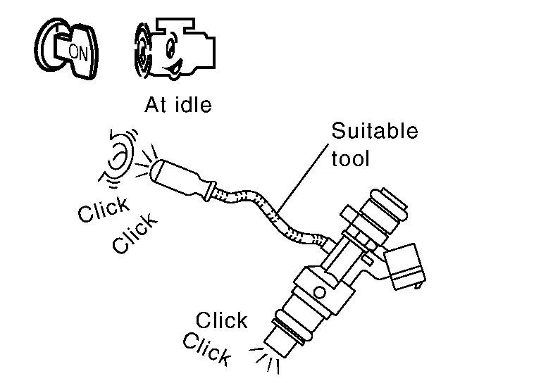
Clicking sound should be heard.
Is the inspection result normal?
YES>>
INSPECTION END
NO>>
Perform trouble diagnosis for FUEL INJECTOR, refer to Diagnosis Procedure.
P0181 Ftt Sensor Nissan Pathfinder SUV
DTC Description
DTC DETECTION LOGIC
| DTC |
CONSULT screen terms (Trouble diagnosis content) |
DTC detection condition | |||
| P0181 | 00 |
FTT SENSOR (Fuel temperature sensor a circuit range/performance) |
A | Diagnosis condition | — |
| Signal (terminal) | Fuel tank temperature sensor signal | ||||
| Threshold | Rationally incorrect voltage from the sensor is sent to ECM, compared with the voltage signals from ECT sensor and intake air temperature sensor. | ||||
| Diagnosis delay time | — | ||||
| B | Diagnosis condition | Engine cold start | |||
| Signal (terminal) | Fuel temperature sensor signal | ||||
| Threshold | The comparison result of signals transmitted to ECM from each temperature sensor (IAT sensor, ECT sensor, EOT sensor, and FTT sensor) shows that the voltage signal of the FTT sensor is higher/lower than that of other temperature sensors. | ||||
| Diagnosis delay time | — | ||||
POSSIBLE CAUSE
Malfunction A
-
Harness or connectors (The FTT sensor circuit is open or shorted)
-
FTT sensor
Malfunction B
-
Harness or connectors (High or low resistance in the FTT sensor circuit)
-
FTT sensor
FAIL-SAFE
Not applicable
DTC Confirmation Procedure
INSPECTION START
Is it necessary to erase permanent DTC?
YES>>
GO TO 7.
NO>>
GO TO 2.
PRECONDITIONING
If DTC Confirmation Procedure has been previously conducted, always perform the following procedure before conducting the next test.
-
Turn ignition switch OFF and wait at least 10 seconds.
-
Turn ignition switch ON.
-
Turn ignition switch OFF and wait at least 10 seconds.
>>
GO TO 3.
PERFORM DTC CONFIRMATION PROCEDURE-I (FOR MALFUNCTION A)
-
Turn ignition switch ON and wait at least 10 seconds.
-
Check 1st trip DTC.
Is 1st trip DTC detected?
YES>>
Proceed to Diagnosis Procedure.
NO>>
GO TO 4.
CHECK ENGINE COOLANT TEMPERATURE
 With CONSULT
-
On CONSULT screen, select “ENGINE”>>“Data Monitor”>>“COOLAN TEMP/S”.
-
Check “COOLAN TEMP/S” value.
“COOLAN TEMP/S” less than 60°C (140°F)?
YES>>
INSPECTION END
NO>>
GO TO 5.
PERFORM DTC CONFIRMATION PROCEDURE-II (FOR MALFUNCTION A)
 With CONSULT
-
Cool engine down until “COOLAN TEMP/S” is less than 60°C (140°F).
-
Wait at least 10 seconds.
-
Check 1st trip DTC.
Is DTC P0181 detected?
YES>>
Proceed to Diagnosis Procedure.
NO>>
GO TO 6.
PERFORM COMPONENT FUNCTION CHECK (FOR MALFUNCTION B)
 NOTE:
NOTE:
Use the component function check to check the overall function of the FTT sensor circuit. During this check, a 1st trip DTC might not be confirmed.
-
Turn ignition switch OFF.
-
Disconnect “fuel level sensor unit and fuel pump” harness connector.
-
Remove fuel level sensor unit. Refer to Removal and Installation.
-
Check resistance between “fuel level sensor unit and fuel pump” terminals by heating with hot water as shown in the figure.

Fuel level sensor unit and fuel pump Condition Resistance Terminal 5 6 Temperature [°C (°F)] 20 (68) 2.3 – 2.7 kΩ 50 (122) 0.79 – 0.90 kΩ
Is the inspection result normal?
YES-1>>
To check malfunction symptom before repair: Refer to Intermittent Incident.
YES-2>>
Confirmation after repair: INSPECTION END
NO>>
Proceed to Diagnosis Procedure.
PRECONDITIONING
If DTC CONFIRMATION PROCEDURE has been previously conducted, always perform the following procedure before conducting the next test.
-
Turn ignition switch OFF and wait at least 10 seconds.
-
Turn ignition switch ON.
-
Turn ignition switch OFF and wait at least 10 seconds.
TEST CONDITION:
-
Before performing the following procedure, do not add fuel.
-
Before performing the following procedure, check that fuel level is between 1/4 and 4/4.
-
Before performing the following procedure, confirm that battery voltage is 11 V or more at idle.
>>
GO TO 8.
PERFORM DTC CONFIRMATION PROCEDURE B
-
Move the Nissan Pathfinder vehicle to a cool place.
 NOTE:
NOTE: Cool the vehicle in an environment of ambient air temperature between −10°C (14°F) and 35°C (95°F).
-
Turn ignition switch OFF and leave the Nissan Pathfinder vehicle for 12 hours.
CAUTION:
Never turn ignition switch ON during this procedure.
 NOTE:
NOTE: The Nissan Pathfinder vehicle must be cooled with the hood open.
-
Start engine and let it idle for 5 minutes or more.
CAUTION:
Never turn ignition switch OFF during idling.
-
Check 1st trip DTC.
Is DTC P0181 detected?
YES>>
Proceed to Diagnosis Procedure.
NO-1>>
To check malfunction symptom before repair: Refer to Intermittent Incident.
NO-2>>
Confirmation after repair: INSPECTION END
Diagnosis Procedure
INSPECTION START
Confirm the detected malfunction (A or B). Refer to DTC Description.
Which malfunction is detected?
A>>
GO TO 2.
B>>
GO TO 6.
CHECK FUEL TANK TEMPERATURE SENSOR POWER SUPPLY
-
Turn ignition switch OFF.
-
Disconnect “fuel level sensor unit and fuel pump” harness connector.
-
Turn ignition switch ON.
-
Check the voltage between “fuel level sensor unit and fuel pump” harness connector and ground.
+ − Voltage
(Approx.)Fuel level sensor unit and fuel pump Connector Terminal B57 5 Ground 5 V
Is the inspection result normal?
YES>>
GO TO 4.
NO>>
GO TO 3.
CHECK FUEL TANK TEMPERATURE SENSOR POWER SUPPLY CIRCUIT
-
Turn ignition switch OFF.
-
Disconnect ECM harness connector.
-
Check the continuity between “fuel level sensor unit and fuel pump” harness connector and ECM harness connector.
Fuel level sensor unit and fuel pump ECM Continuity Connector Terminal Connector Terminal B57 5 E32 180 Existed -
Also check harness for short to power and short to ground.
Is the inspection result normal?
YES>>
Perform the trouble diagnosis for ECM power supply circuit. Refer to Diagnosis Procedure.
NO>>
Repair or replace error-detected parts.
CHECK FUEL TANK TEMPERATURE SENSOR GROUND CIRCUIT
-
Turn ignition switch OFF.
-
Disconnect ECM harness connector.
-
Check the continuity between “fuel level sensor unit and fuel pump” harness connector and ECM harness connector.
Fuel level sensor unit and fuel pump ECM Continuity Connector Terminal Connector Terminal B57 6 E32 200 Existed -
Also check harness for short to power.
Is the inspection result normal?
YES>>
GO TO 5.
NO>>
Repair or replace error-detected parts.
CHECK ECM GROUND CIRCUIT
-
Check the continuity between ECM harness connector and ground.
ECM — Continuity Connector Terminal F78 3 Ground Existed F79 87 E32 199 201 204 -
Also check harness for short to power.
Is the inspection result normal?
YES>>
GO TO 6.
NO>>
Repair or replace error-detected parts.
CHECK FUEL TANK TEMPERATURE SENSOR
Refer to Component Inspection (Fuel Tank Temperature Sensor).
Is the inspection result normal?
YES>>
INSPECTION END
NO>>
Replace “fuel level sensor unit and fuel pump”. Refer to Removal and Installation.
Component Inspection (Fuel Tank Temperature Sensor)
CHECK FUEL TANK TEMPERATURE SENSOR
-
Turn ignition switch OFF.
-
Disconnect “fuel level sensor unit and fuel pump” harness connector.
-
Remove fuel level sensor unit. Refer to Removal and Installation.
-
Check resistance between “fuel level sensor unit and fuel pump” terminals by heating with hot water as shown in the figure.
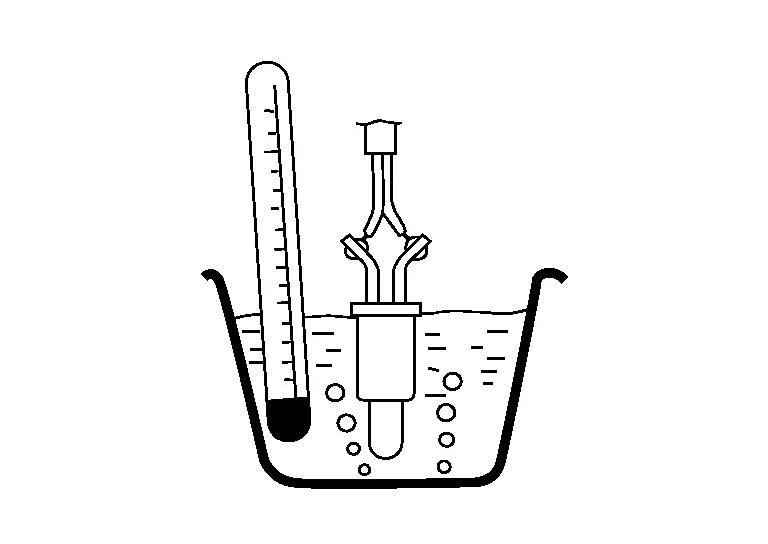
Fuel level sensor unit and fuel pump Condition Resistance Terminal 5 6 Temperature [°C (°F)] 20 (68) 2.3 – 2.7 kΩ 50 (122) 0.79 – 0.90 kΩ
Is the inspection result normal?
YES>>
INSPECTION END
NO>>
Replace “fuel level sensor unit and fuel pump”. Refer to Removal and Installation.
P01f0 Engine Coolant Temperature Nissan Pathfinder R53
DTC Description
DTC DETECTION LOGIC
| DTC |
CONSULT screen terms (Trouble diagnosis content) |
DTC detection condition | ||
| P01F0 | 00 |
Coolant temperature (Coolant temperature relapsed below diagnostic monitoring temperature) |
Diagnosis condition |
|
| Signal (terminal) | Engine coolant temperature sensor signal | |||
| Threshold | When the engine coolant temperature is lower than threshold value, after Nissan Pathfinder vehicle is driven at 60km/h (37 MPH) or more for certain period. Make sure that the engine is warmed up to normal operating temperature before driving. Make sure that the engine is warmed up to normal operating temperature before driving. | |||
| Diagnosis delay time | 40 seconds or more | |||
POSSIBLE CAUSE
-
Thermostat
-
Engine coolant temperature sensor
-
Leakage from sealing portion of thermostat
FAIL-SAFE
Not applicable
Confirmation Procedure
 NOTE:
NOTE:
Never refuel before and during the following procedure.
CHECK DTC PRIORITY
If DTC P01F0 is displayed with DTC P0116, P0117, P0118, or P0128, first perform the trouble diagnosis for DTC P0116, P0117, P0118, or P0128.
Is other DTC detected?
YES>>Perform diagnosis of applicable. Refer to DTC Index.
NO>>GO TO 2.
PRECONDITIONING
If DTC Confirmation Procedure has been previously conducted, always perform the following procedure before conducting the next test.
-
Turn ignition switch OFF and wait at least 10 seconds.
-
Turn ignition switch ON.
-
Turn ignition switch OFF and wait at least 10 seconds.
>>
GO TO 3.
PERFORM DTC CONFIRMATION PROCEDURE
 With CONSULT
-
Start engine and warm it up to the normal operating temperature.
-
Maintain the hold Nissan Pathfinder vehicle speed at more than 60 km/h (37 MPH) for at least 40 consecutive seconds.
CAUTION:
Always drive Nissan Pathfinder vehicle in safe manner according to traffic conditions and obey all traffic laws.
 NOTE:
NOTE:
Keeping the accelerator pedal as steady as possible at approximately more than 1/8.
Is DTC detected?
YES>>Refer to DTC Diagnosis Procedure.
NO-1>>To check malfunction symptom before repair: Refer to Intermittent Incident.
NO-2>>Confirmation after repair: INSPECTION END
DTC Diagnosis Procedure
CHECK DTC PRIORITY
If DTC P01F0 is displayed with DTC P0116, P0117, P0118, or P0128, first perform the trouble diagnosis for DTC P0116, P0117, P0118, or P0128.
Is other DTC detected?
YES>>Perform diagnosis of applicable. Refer to DTC Index.
NO>>GO TO 2.
CHECK ENGINE COOLANT TEMPERATURE SENSOR
Check the engine coolant temperature sensor. Refer to Component Inspection (Engine Coolant Temperature Sensor).
Is the inspection result normal?
YES>>GO TO 3.
NO>>Replace engine coolant temperature sensor. Refer to Exploded View.
CHECK THERMOSTAT
Check the thermostat. Refer to Removal and Installation.
Is the inspection result normal?
YES>>INSPECTION END
NO>>Replace thermostat.
P025b Fuel Pump Module a Nissan Pathfinder Fifth generation
DTC Description
DTC DETECTION LOGIC
| DTC |
CONSULT screen terms (Trouble diagnosis content) |
DTC detection condition | |
| P025B |
FUEL PUMP MODULE A (Fuel Pump Module A Control Circuit Range/Performance) |
Diagnosis condition | Engine cranking |
| Signal (terminal) | Fuel pump control module signal | ||
| Threshold | A signal voltage of the FPCM to the ECM is too low | ||
| Diagnosis delay time | — | ||
POSSIBLE CAUSE
-
Harness or connectors
-
FPCM circuit is open or shorted
-
Fuel pump circuit is open or shorted
-
-
FPCM
FAIL-SAFE
Not applicable
DTC Confirmation Procedure
PRECONDITIONING
If DTC Confirmation Procedure has been previously conducted, always perform the following procedure before conducting the next test.
-
Turn ignition switch OFF and wait at least 10 seconds.
-
Turn ignition switch ON.
-
Turn ignition switch OFF and wait at least 10 seconds.
TESTING CONDITION:
-
Before performing the following procedure, confirm that battery voltage is between 12 - 15 V at idle.
-
Before performing the following procedure, check that the engine coolant temperature is −10°C (14°F) or more.
>>
GO TO 2.
PERFORM DTC CONFIRMATION PROCEDURE
-
Start engine and let it idle for at least 5 seconds.
If engine does not start, crank engine for at least 5 seconds.
-
Check DTC.
Is DTC P025B detected?
YES>>Refer to DTC Diagnosis Procedure.
NO-1>>To check malfunction symptom before repair: Refer to Intermittent Incident.
NO-2>>Confirmation after repair: INSPECTION END
DTC Diagnosis Procedure
CHECK FUSE
-
Turn ignition switch OFF.
-
Pull out 20 A fuse (No. 85) from IPDM E/R.
-
Check that 20 A fuse is not blowing.
Is the fuse blown (open)?
YES>>Replace the fuse after repairing the applicable circuit.
NO>>GO TO 2.
CHECK FPCM POWER SUPPLY
-
Turn ignition switch OFF.
-
Disconnect FPCM harness connector.
-
Turn ignition switch ON.
-
Check the voltage between FPCM harness connector and ground.
+ − Voltage FPCM Connector Terminal B58 1 Ground Battery voltage
Is the inspection result normal?
YES>>GO TO 4.
NO>>GO TO 3.
CHECK FPCM POWER SUPPLY CIRCUIT
-
Turn ignition switch OFF.
-
Disconnect IPDM E/R harness connector.
-
Check the continuity between FPCM harness connector and IPDM E/R harness connector.
FPCM IPDM E/R Continuity Connector Terminal Connector Terminal B58 1 E121 46 Existed -
Also check harness for short to power and short to ground.
Is the inspection result normal?
YES>>Perform trouble diagnosis for power supply circuit.
NO>>Repair or replace error-detected parts.
CHECK FPCM GROUND CIRCUIT
-
Turn ignition switch OFF.
-
Check the continuity between FPCM harness connector and ground.
FPCM — Continuity Connector Terminal B58 4 Ground Existed -
Also check harness for short to power.
Is the inspection result normal?
YES>>GO TO 5.
NO>>Repair or replace error-detected parts.
CHECK FPCM INPUT AND OUTPUT CIRCUIT
-
Disconnect ECM harness connector.
-
Check the continuity between FPCM harness connector and ECM harness connector.
FPCM ECM Continuity Connector Terminal Connector Terminal B58 2 E32 188 Existed 3 182 -
Also check harness for short to power and short to ground.
Is the inspection result normal?
YES>>GO TO 6.
NO>>Repair or replace error-detected parts.
CHECK FUEL PUMP CONTROL CIRCUIT
-
Disconnect “fuel level sensor unit and fuel pump” harness connector.
-
Check the continuity between FPCM harness connector and “fuel level sensor unit and fuel pump” harness connector.
FPCM Fuel level sensor unit and fuel pump Continuity Connector Terminal Connector Terminal B58 5 B57 7 Existed 6 8 -
Also check harness for short to power and short to ground.
Is the inspection result normal?
YES>>GO TO 7.
NO>>Repair or replace error-detected parts.
CHECK FPCM
Refer to Component Inspection (Fuel Pump Control Module).
Is the inspection result normal?
YES>>INSPECTION END
NO>>Replace FPCM. Refer to Removal and Installation.

Nissan Pathfinder (R53) 2022-2026 Service Manual
Dtc/circuit Diagnosis (P0116 Engine Coolant Temperature Sensor ... P025b Fuel Pump Module a)
- P0116 Engine Coolant Temperature Sensor
- P0122 Tp Sensor
- P0127 Iat Sensor
- P0128 Thermostat Function
- P0130 A/f Sensor 1
- P0138 Ho2s2
- P0171 Fuel Injection System Function
- P0181 Ftt Sensor
- P01f0 Engine Coolant Temperature
- P025b Fuel Pump Module a
Contact Us
Nissan Pathfinder Info Center
Email: info@nipathfinder.com
Phone: +1 (800) 123-4567
Address: 123 Pathfinder Blvd, Nashville, TN 37214, USA
Working Hours: Mon–Fri, 9:00 AM – 5:00 PM (EST)
