Nissan Pathfinder: Vq35dd - Unit Disassembly and Assembly. Cylinder Block ++
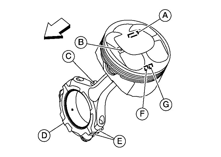
Exploded View
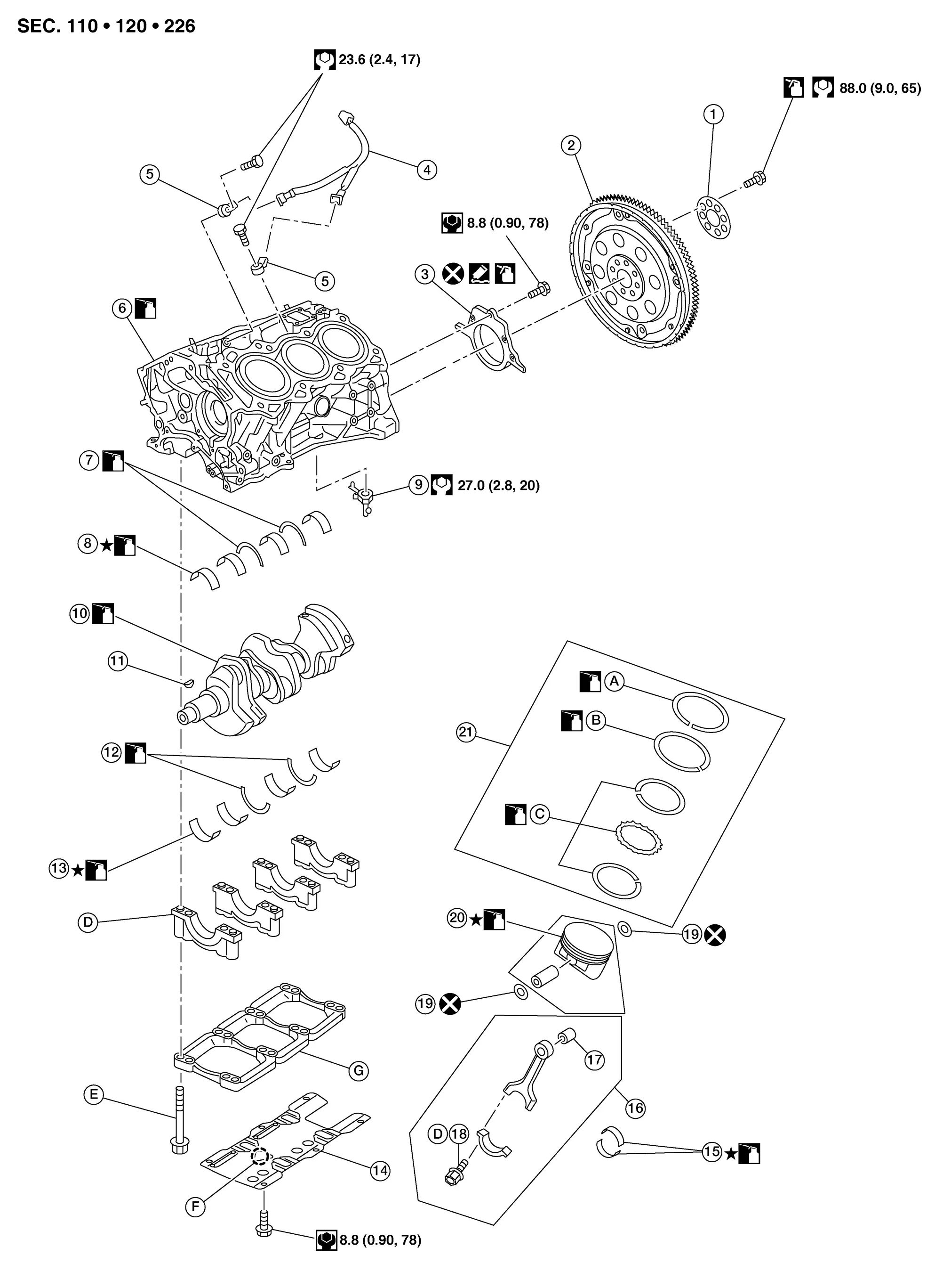
| 1. | Reinforcement plate | 2. | Drive plate | 3. | Rear oil seal retainer |
| 4. | Sub harness | 5. | Knock sensor | 6. | Cylinder block |
| 7. | Thrust bearing (upper) | 8. | Main bearing (upper) | 9. | Oil jet |
| 10. | Crankshaft | 11. | Crankshaft key | 12. | Thrust bearing (lower) |
| 13. | Main bearing (lower) | 14. | Baffle plate | 15. | Connecting rod bearing |
| 16. | Connecting rod | 17. | Connecting rod bushing | 18. | Connecting rod bolt |
| 19. | Snap ring | 20. | Piston | 21. | Piston ring set |
| A. | Top ring | B. | Second ring | C. | Oil rings |
| D. | Main bearing cap | E. | Refer to Disassembly and Assembly. | F. | Front mark |
| G. | Main bearing beam |
 : Main bearing (upper), main bearing (lower) and connecting rod bearings are replaced in pairs.
Disassembly and Assembly
CAUTION:
-
Apply new engine oil to parts as marked in illustrations before installation.
-
Place removed parts such as bearings and bearing caps in their proper order and direction.
-
Do not allow any magnetic materials to contact the signal plate teeth on the drive plate.
DISASSEMBLY
Remove the cylinder heads. Refer to Removal and Installation.
Disconnect the harness connectors from the knock sensors and remove the sub harness.
Remove the knock sensor.
CAUTION:
Carefully handle sensor to avoid shocking it.
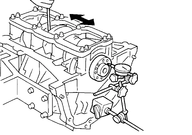
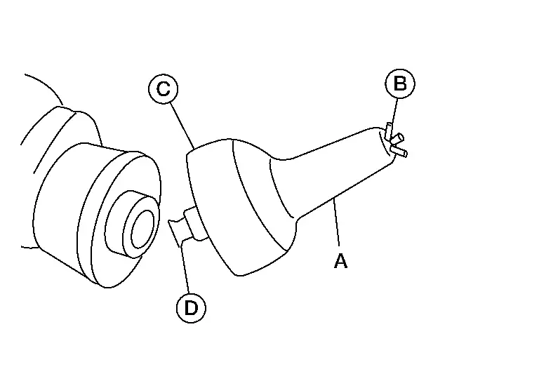
Remove the water drain plug (B) and connector bolt (C) from the cylinder block (if necessary).

CAUTION:
Do not reuse copper sealing washer (A).
 |
: Engine front |
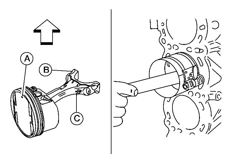
Remove the piston and connecting rod assemblies using the following procedure:Before removing the piston and connecting rod assembly, check the connecting rod side clearance. Refer to Cylinder Block. Position the crankshaft pin corresponding to the connecting rod to be removed onto the bottom dead center. Remove the connecting rod cap bolts and remove the connecting rod cap. Using a hammer handle or similar tool, push the piston and connecting rod assembly out to the cylinder head side.
Remove the connecting rod bearings.
CAUTION:
When removing the connecting rod side bearings, note the installation position. Keep them in the correct order.
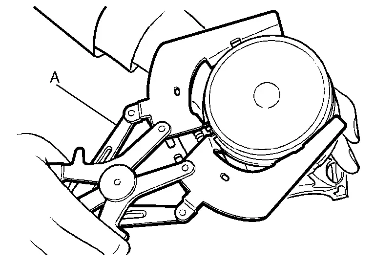
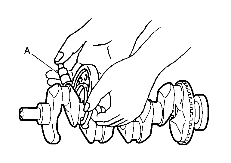
Remove the piston rings from the piston using suitable tool (A).
-
Before removing the piston rings, check the piston ring side clearance. Refer to Inspection.
CAUTION:
-
When removing the piston rings, do not damage the piston. Do not expand the rings excessively.
-
Be careful to mark the rings if they are to be reused so they are installed in their original position.
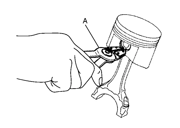
Remove the piston from the connecting rod as follows.Using suitable tool (A), remove the snap rings.
CAUTION:
Do not reuse snap rings.
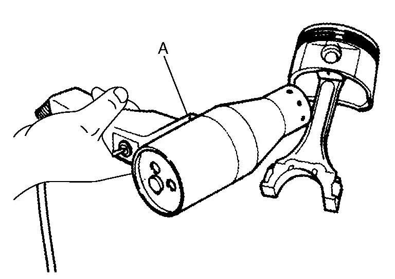
Heat the pistons to 60° - 70°C (140° - 158°F) using a suitable tool (A).
WARNING:
Pistons contain heat. When working, wear protective equipment to avoid getting burned.
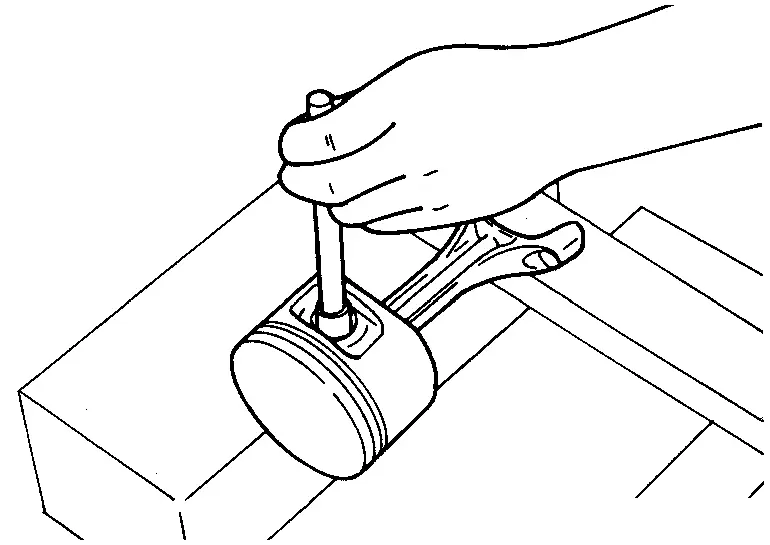
Push out the piston pin with a suitable tool with an outer diameter of approximately 20 mm (0.8 in).
Remove the baffle plate from the main bearing beam.
Loosen the bolts in reverse of the order shown and remove the main bearing beam, bearing caps and crankshaft.
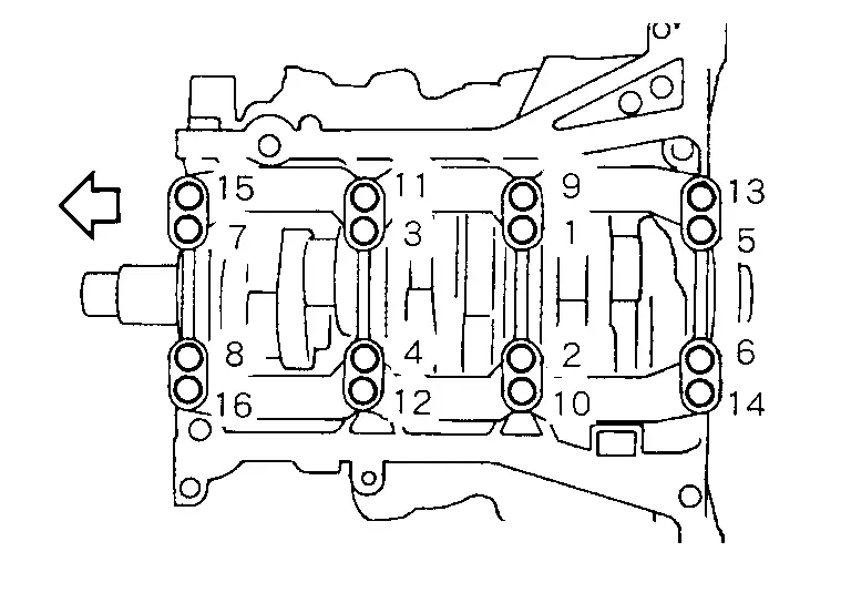
-
Before loosening the main bearing cap bolts, measure the crankshaft side clearance. Refer to Inspection.

: Engine front
Remove the oil jets.
Remove the main bearings and thrust bearings from the cylinder block and main bearing caps.
-
When removing them, note the direction and position. Keep them in the correct order for installation.
ASSEMBLY
Blow out the engine coolant and engine oil passages and cylinder bore to remove any foreign materials.
CAUTION:
Use goggles to protect your eyes.
Install the cylinder block drain plugs (if removed).
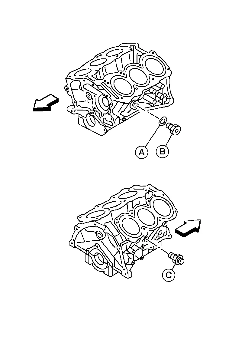
-
Apply sealant to the thread of the water drain plug (B), connector bolt (C).
Use Genuine High Performance Thread Sealant or equivalent. Refer to Recommended Chemical Products and Sealants.
CAUTION:
-
Do not reuse copper sealing washer (A).
-
Installation should be done within 5 minutes of applying liquid gasket.
-
Do not fill the engine with engine coolant for at least 30 minutes after the components are installed to allow the sealant to cure.
Water drain plug (B) : 62 N·m (6.3 kg-m, 46 ft-lb) Connector bolt (C) : 39.2 N·m (4.0 kg-m, 29 ft-lb) 
: Engine front -
Install the oil jets.
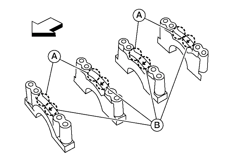
Install the main bearings and the thrust bearings.Remove dust, dirt, and engine oil on the bearing mating surfaces of the cylinder block and the main bearing cap. Install the thrust bearings (1) to both sides of the No. 3 journal housing (B) on the cylinder block and the main bearing cap.
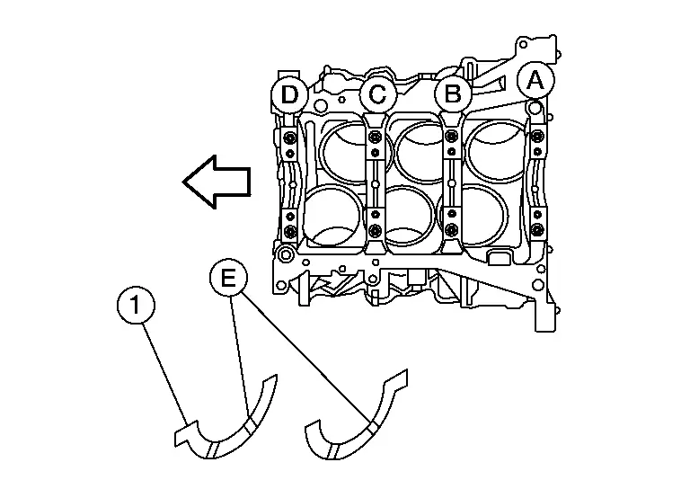
-
Install the thrust bearings with the oil groove (E) facing the crankshaft arm (outside).
-
Install bearing with a projection on one end on cylinder block and bearing with a projection at center on cap. Align each projection with mating notch.
| (A) | : No. 4 journal housing |
| (C) | : No. 2 journal housing |
| (D) | : No. 1 journal housing |
 |
: Engine front |
Set the upper main bearings in their proper positions on the cylinder block.
-
Confirm the correct main bearings are used. Refer to Inspection.
 NOTE:
NOTE:
Main bearing (upper) have an oil groove and the main bearing (lower) do not have an oil groove.
Instructions for the re-use of the main bearing cap bolts.
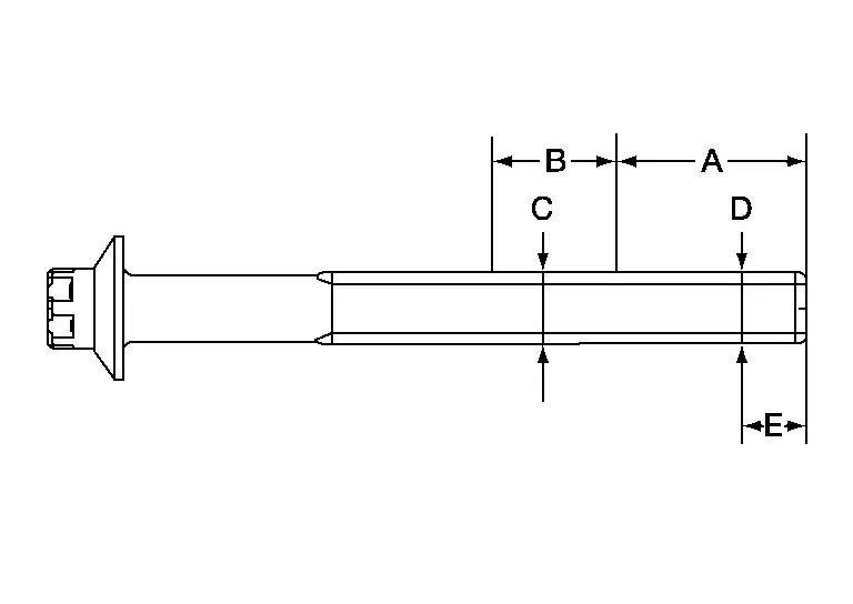
-
A plastic zone tightening method is used for tightening the main bearing cap bolts. Measure (D) and (C) as shown.
-
For (C), select the minimum diameter in the measuring area.
-
If the difference between (D) and (C) exceeds the limit, replace the bolts for assembly.
| Limit [(D) - (C)] | : 0.11 mm (0.0043 in) |
| (A) | : 30 mm (1.18 in) |
| (B) | : 20 mm (0.79 in) |
| (E) | : 10 mm (0.39 in) |
Install the crankshaft, lower main bearings, main bearing caps, main bearing beam, and bearing cap bolts using the following procedure:Make sure that the front marks on the main bearing beam faces the front of the engine.
| (A) | : Main bearing journal number |
| (B) | : Front mark |
 |
: Engine front |

CAUTION:
Measure the tightening angle using Tool. Do not measure visually.
| Step 1 | : 44.2 N·m (4.5 kg-m, 33 ft-lb) |
| Step 2 | : 90° – 95° degrees clockwise |
| Tool number | : KV10112100 (BT-8653-A) |
Measure crankshaft end play.
-
If beyond the limit, replace the thrust bearing with a new one.
| Standard and Limit | : Refer to Cylinder Block. |
Install the piston to the connecting rod.Using suitable snap ring pliers, install the snap ring fully into the pin-groove of the piston rear side.
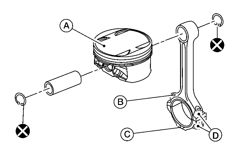
CAUTION:
Do not reuse snap rings.
| (A) | : Piston front mark |
| (B) | : Oil hole |
| (C) | : Connecting rod front mark |
| (D) | : Cylinder No. |
-
Heat the piston until the piston pin can be pushed in by hand without excessive force [approx. 60 - 70°C (140 - 158°F)]. From the front to the rear, insert the piston pin into the piston and through the connecting rod.
WARNING:
Pistons contain heat. When working, wear protective equipment to avoid getting burned.
-
Assemble so that the piston front mark (B) on the crown and the oil hole (C), connecting rod front mark (D) and Cylinder No. (E) on the connecting rod are positioned as shown.
(A) : Crown ID code (F) : Piston grade number (G) : Piston type (RH or LH) 
: Engine front

-
After installing, check that the connecting rod pivots smoothly on the pin.
CAUTION:
Do not reuse snap rings.
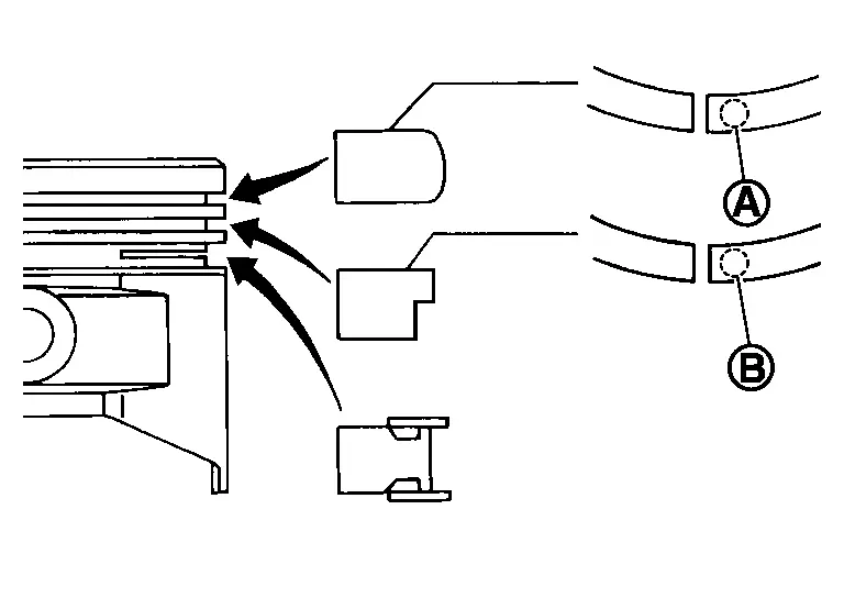
Using a piston ring expander, install the piston rings.
CAUTION:
-
Do not damage the piston.
-
When the piston rings are not replaced, remount the rings in their original positions.
-
When replacing the piston rings, those without stamped surface can be mounted either side up.
-
Install the second ring with the stamped surface facing upward.
| (A) | : No marking |
| (B) | : Z4 |
-
Position each ring with the gap as shown, referring to the piston front mark (E).
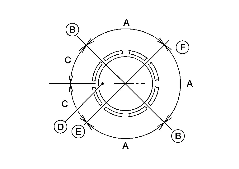
(A) : 90° (B) : Oil ring upper or lower rail gap (either of them) (C) : 45° (D) : Piston front mark (E) : Second ring gap (F) : Top ring gap
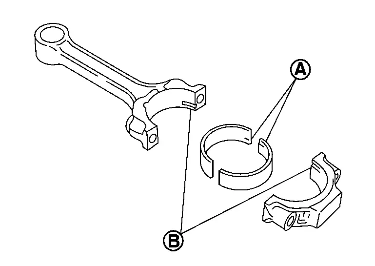
Install the connecting rod bearings to the connecting rod and the connecting rod cap.
-
When installing the connecting rod bearings, apply engine oil to the bearing surface (crankshaft side). Do not apply engine oil to the back surface (connecting rod and cap side), but thoroughly clean it.
-
When installing, align the connecting rod bearing protrusion (A) with the notch (B) of the connecting rod to install.
-
Check that the oil holes on the connecting rod and on the corresponding bearing are aligned.
Install the piston and connecting rod assembly into the corresponding cylinder.
-
Position the crankshaft pin corresponding to the connecting rod to be installed onto the bottom dead center.
-
Apply engine oil sufficiently to the cylinder bore, piston skirt, piston ring, and crankshaft pin.
-
Match the cylinder position with the cylinder No. (B) on the connecting rod to install.
-
Install the piston with the piston front mark (A) on the crown facing the front of the engine (
 ) using suitable tool.
(C) : Oil hole
CAUTION:
Do not damage the crankshaft pin and cylinder wall, resulting from interference of the connecting rod big end.
Install the connecting rod cap.
-
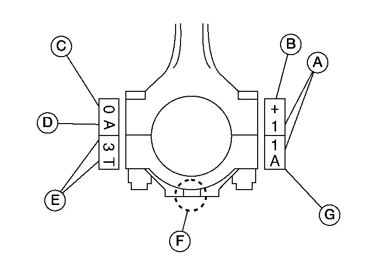
Match the stamped cylinder number marks (A) on the connecting rod with those on the cylinder cap for installation.
-
Install the piston connecting rod assembly and cap so that the front mark (F) on the cap and piston are facing the front of the engine.
-
Lubricate the threads and seat surfaces with new engine oil.
| (B) | : Stamping mark |
| (C) | : Small end hole grade |
| (D) | : Mass grade |
| (E) | : Production control mark |
| (G) | : Production control mark |
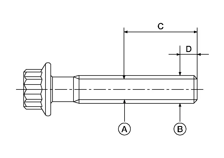
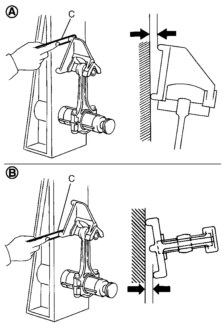
Check the connecting rod cap bolts before reusing, then install in their original position in the connecting rod. The bolts should screw in smoothly by hand.
-
Measure the outer diameter of the connecting rod cap bolt as shown.
Limit [(B) - (A)] : 0.12 mm (0.0047 in) (C) : 19 mm (0.75 in) (D) : 5 mm (0.20 in) -
When reduction exceeds the limit (when it becomes thinner), replace with new connecting rod bolt.
Tighten the connecting rod bolts in two steps using Tool:
CAUTION:
Measure the tightening angle using Tool. Do not measure visually.
| Step 1 | : 19.6 N·m (2.0 kg-m, 14 ft-lb) |
| Step 2 | : 90° - 95° degrees clockwise |
| Tool number | : KV10112100 (BT-8653-A) |
-
After tightening the nuts, make sure that the crankshaft rotates smoothly.
-
Check the connecting rod side clearance. If beyond the limit, replace the connecting rod and/or crankshaft.
Connecting rod side clearance: Standard and Limit : Refer to Cylinder Block.
Install the baffle plate to the main bearing beam.
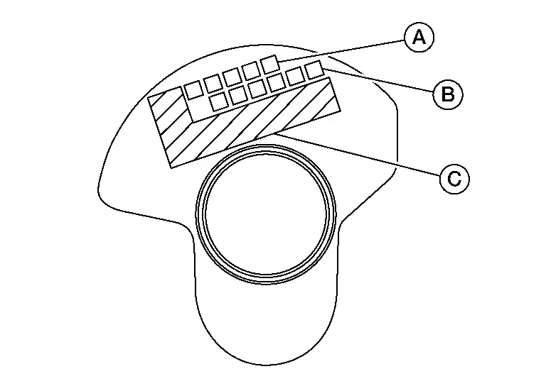
Install the knock sensors.
-
Make sure that there is no foreign material on the cylinder block mating surface and the back surface of the knock sensor.
-
Install the bank 2 knock sensor (1) and then the bank 1 knock sensor (2).
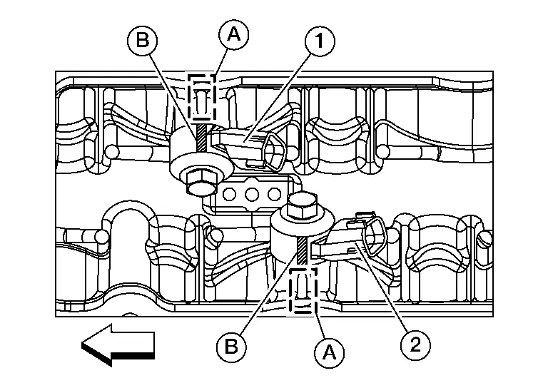
-
Align marking (B) on knock sensor with casting (A) on cylinder block.
-
Do not tighten the bolts while holding the connector.
-
Make sure that the knock sensor does not interfere with other parts.
CAUTION:
If any impact by dropping occurs to the knock sensor, replace it with new one.
Remove engine from the stand.
Install a new rear oil seal retainer using Tool (A).
| Tool number (A) | : — (NI-47128) |
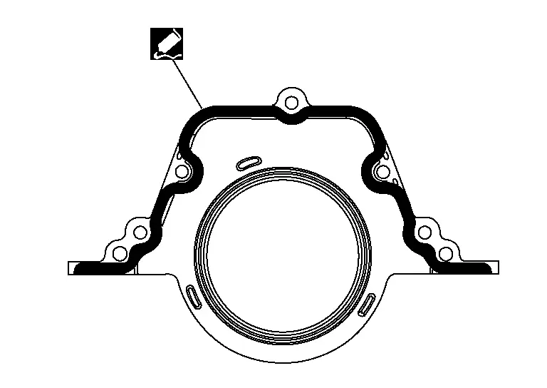
Use Genuine Silicone RTV Sealant, or equivalent. Refer to Recommended Chemical Products and Sealants.
CAUTION:
-
Do not reuse rear oil seal retainer.
-
Installation should be done within 5 minutes after applying liquid gasket.
-
Do not fill the engine with engine oil for at least 30 minutes after the components are installed to allow the sealant to cure.
Assembly of the remaining components is in the reverse order of disassembly.
Inspection
PISTON AND PISTON PIN CLEARANCE
Inner Diameter of Piston Pin Hole
-
Measure the inner diameter of piston pin hole using suitable tool (A).
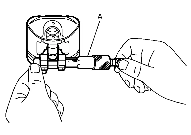
Standard : Refer to Cylinder Block.
Outer Diameter of Piston Pin
-
Measure outer diameter of piston pin using suitable tool (A).
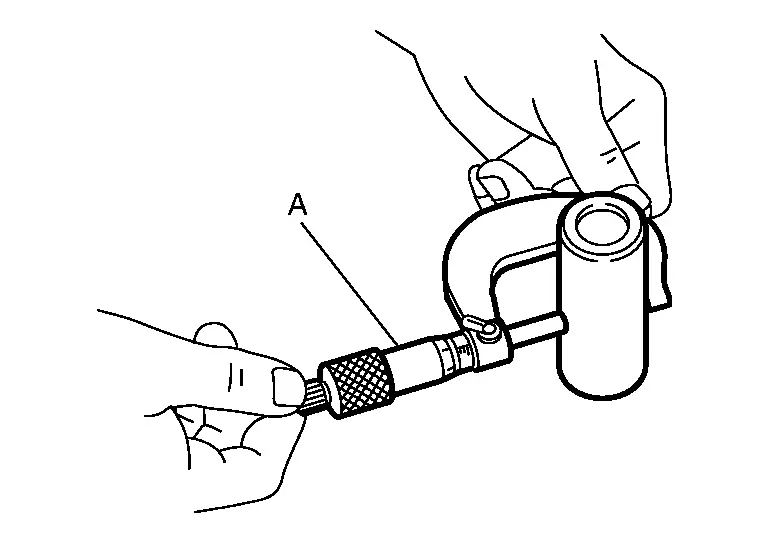
Standard : Refer to Cylinder Block.
Piston and Piston Pin Interference Fit
(Piston to piston pin oil clearance) = (Piston pin hole diameter) - (Piston pin outer diameter)
| Standard | : Refer to Cylinder Block. |
-
If clearance is exceeds specification, replace either or both of piston/piston pin assembly and connecting rod assembly with reference to specification of each part.
PISTON RING SIDE CLEARANCE
-
Measure side clearance of piston ring and piston ring groove using suitable tool (C).
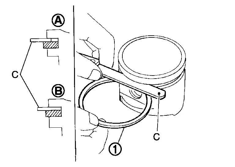
| Standard and Limit | : Refer to Cylinder Block. |
| (A) | : OK |
| (B) | : NG |
-
If out of specification, replace piston ring assembly. If clearance exceeds maximum limit with new rings, replace piston.
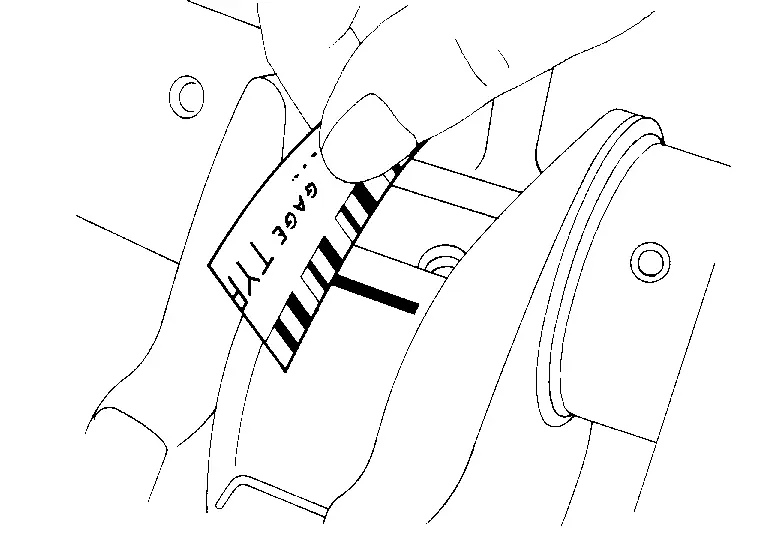
PISTON RING END GAP
-
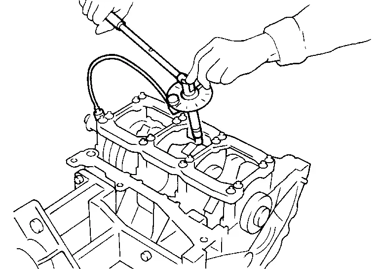
Using piston (1), insert (A) piston ring (2) until it is in the middle of the cylinder bore and measure the end gap using suitable tool (B).
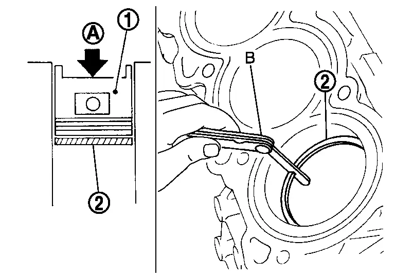
| Standard and Limit | : Refer to Cylinder Block. |
-
If measured value exceeds limit replace piston ring and measure again. If it still exceeds the limit replace cylinder block.
CONNECTING ROD BEND AND TORSION
-
Check with a connecting rod aligner.
Limit : Refer to Cylinder Block. -
If it exceeds the limit, replace connecting rod assembly.
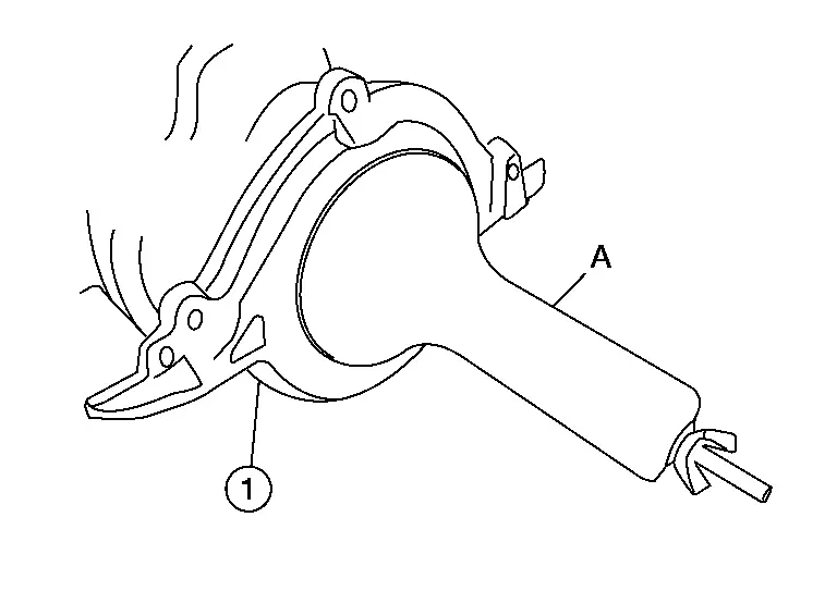
CONNECTING ROD BEARING HOUSING DIAMETER (BIG END)
-
Install the connecting rod cap (1) without the connecting rod bearing installed and tighten the connecting rod bolts. Refer to Disassembly and Assembly.
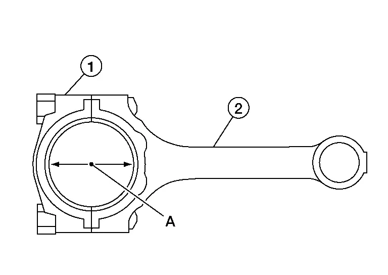
(2) : Connecting rod (A) : Measuring direction of inner diameter -
Measure inner diameter of connecting rod (big end) using a suitable tool.
Standard : Refer to Cylinder Block. -
If it exceeds the standard, replace connecting rod assembly.
CONNECTING ROD BUSHING OIL CLEARANCE (SMALL END)
Inner Diameter of Connecting Rod (Small End)
-
Measure inner diameter of piston pin bushing using suitable tool (A).
Standard : Refer to Cylinder Block.
Outer Diameter of Piston Pin
-
Measure outer diameter of piston pin using suitable tool (A).

Standard : Refer to Cylinder Block.
Connecting Rod Bushing Oil Clearance (Small End)
(Connecting rod small end oil clearance) = (Inner diameter of connecting rod small end) – (Outer diameter of piston pin)
| Standard and Limit | : Refer to Cylinder Block. |
-
If the measured value exceeds the standard, replace the connecting rod assembly and/or piston and piston pin assembly.
-
If replacing the piston and piston pin assembly, use the Table for Selective Fitting for Piston to select the piston corresponding to the applicable bore grade of the cylinder block to be used. Follow the "PISTON-TO-CYLINDER BORE CLEARANCE" procedure.
CYLINDER BLOCK DISTORTION
-
Using a suitable tool, remove any old gasket material on the cylinder block surface and remove any engine oil, scale, carbon, or other contamination.
CAUTION:
Be careful not to allow gasket flakes to enter the engine oil or engine coolant passages.
-
Measure distortion on cylinder block upper face at some different points in six directions using suitable tools (A/B).
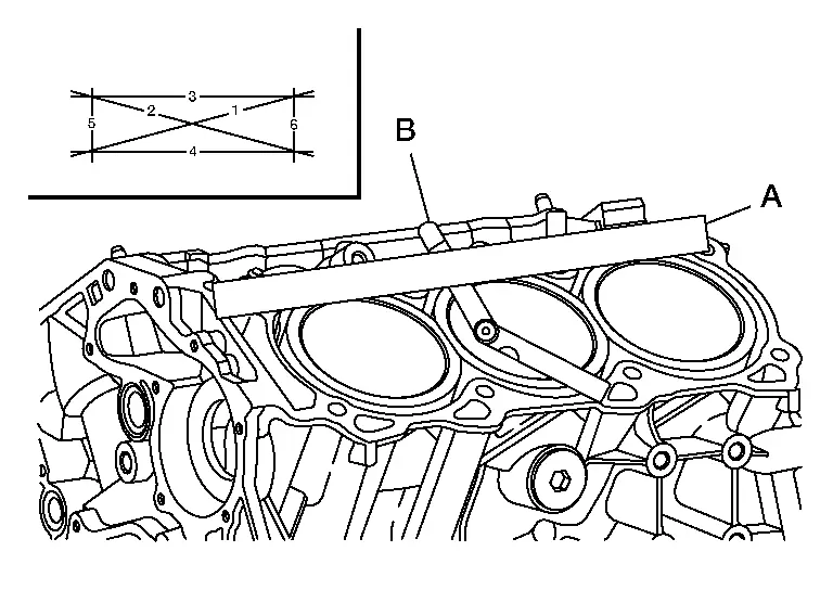
| Limit | : Refer to Cylinder Block. |
-
If out of specification, resurface the cylinder block. The allowable amount of resurfacing is dependent on the amount of any cylinder head resurfacing. The resurfacing limit is [amount of cylinder head resurfacing] + [amount of cylinder block resurfacing] = 0.2 mm (0.008 in).
Cylinder block height : 214.95 - 215.05 mm (8.4626 - 8.4665 in)
INNER DIAMETER OF MAIN BEARING HOUSING
-
Install the main bearing caps with the main bearings removed, and tighten the bolts to the specified torque.
-
Using suitable tool, measure the inner diameter (A) of the main bearing housing.

| Standard | : Refer to Cylinder Block. |
-
If out of the standard, replace the cylinder block and main bearing caps as an assembly.
 NOTE:
NOTE:
These components cannot be replaced as a single unit, because they were processed together.
PISTON-TO-CYLINDER BORE CLEARANCE
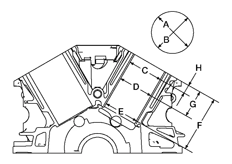
Using suitable tool, measure cylinder bore for wear, out-of-round and taper at (C), (D) and (E). The (A) axis is in the longitudinal direction of the engine.

| Out-of-round [Difference between (A) and (B)] | |
| Limit | : Refer to Cylinder Block. |
| Taper [Difference between (C), (D) and (E) in direction (A)] | |
| Limit | : Refer to Cylinder Block. |
| (F) | : 120 mm (4.72 in) |
| (G) | : 60 mm (2.36 in) |
| (H) | : 10 mm (0.39 in) |
If it exceeds the limit, rebore all cylinders. Replace cylinder block if necessary.
Check for scratches or other damage. If scratches or damage found, hone it.
-
If both cylinder block and piston are replaced with new ones, select piston of the same grade number punched on cylinder block rear position. These numbers are punched in either Arabic or Roman numerals.

(A) : Cylinder bore grade (B) : Main journal grade (C) : Management code 
: Engine front
Measure piston skirt diameter, using suitable tool.
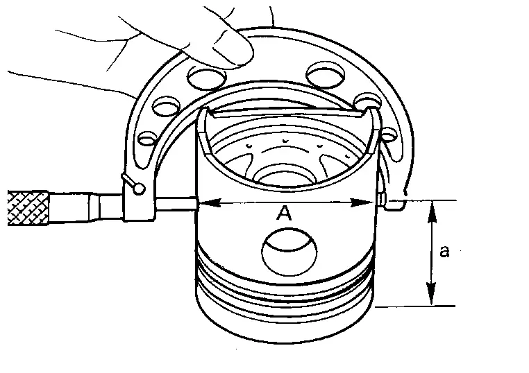
| Piston diameter (A) | : Refer to Cylinder Block. |
| Measuring point (a) (Distance from the top) | : 38.0 mm (1.496 in) |
Check that piston-to-bore clearance is within specification.
-
Calculate by piston skirt diameter and cylinder bore inner diameter [direction (B), position (D)].
(Clearance) = (Cylinder bore inner diameter) – (Piston skirt diameter) Standard : Refer to Cylinder Block. (A) : Used for measuring cylinder bore out-of-round (C) : Used for measuring cylinder bore taper (E) : Used for measuring cylinder bore taper (F) : 120 mm (4.72 in) (G) : 60 mm (2.36 in) (H) : 10 mm (0.39 in)
Re-boring Cylinder Bore
Cylinder bore size is determined by adding piston-to-bore clearance to piston diameter.
| Rebored size calculation | : D = A + B − C |
| where, | |
| (D) | : Bored diameter |
| (A) | : Piston diameter as measured |
| (B) | : Piston-to-bore clearance |
| (C) | : Honing allowance 0.02 mm (0.0008 in) |
Install main bearing caps and main bearing beam, and tighten to the specified torque. Otherwise, cylinder bores may be distorted after boring. Refer to Exploded View.
Cut cylinder bores.
-
When any cylinder needs boring, all other cylinders must also be bored.
-
Do not cut too much out of cylinder bore at a time. Cut only 0.05 mm (0.0020 in) or so in diameter at a time.
Hone cylinders to obtain specified piston-to-bore clearance.
Measure finished cylinder bore for out-of-round and taper.
-
Measurement should be done after cylinder bore cools down.
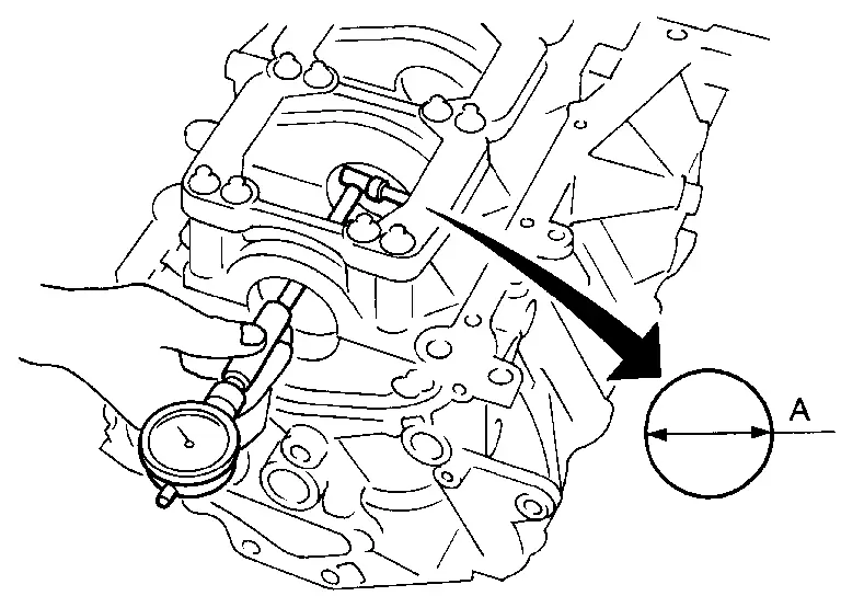
CRANKSHAFT
Check the crankshaft main and pin journals for scoring, wear, or cracks.
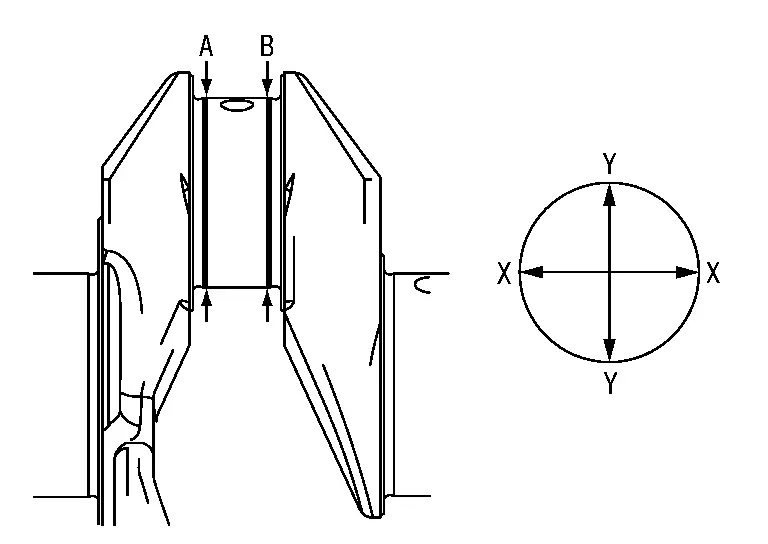
Measure the journals for taper and out-of-round.
| Standard | |
| Out-of-round [(X) — (Y)] | : Refer to Cylinder Block. |
| Taper [(A) - (B)] | : Refer to Cylinder Block. |
Measure crankshaft runout.
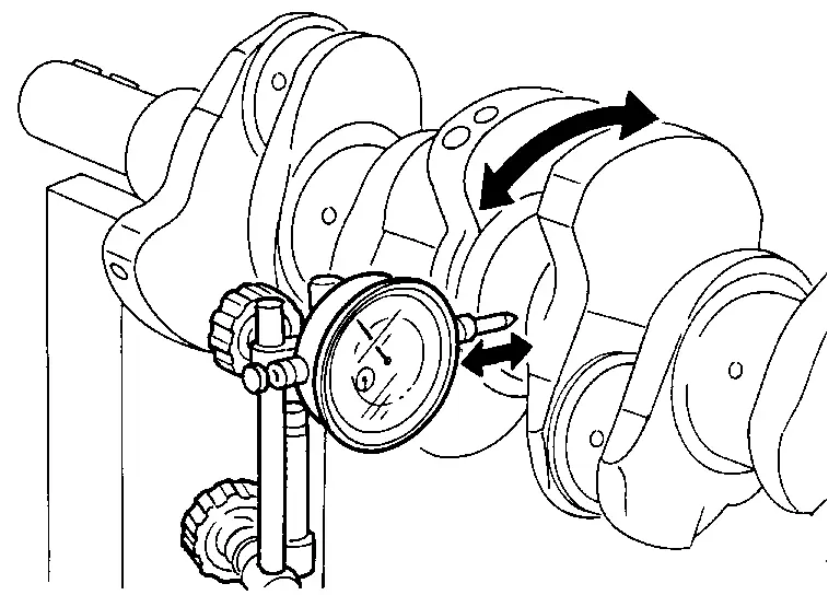
| Runout (total indicator reading) | |
| Standard and Limit | : Refer to Cylinder Block. |
BEARING CLEARANCE
-
Use either of the following two methods, however method (A) gives more reliable results and so is the preferred method.
Method A (Using Bore Gauge and Micrometer)
Main Bearing
Set the main bearings in their proper positions on the cylinder block and the main bearing cap.
 NOTE:
NOTE:
Main bearing (upper) have an oil groove and the main bearing (lower) do not have an oil groove.
Install the main bearing caps and bearing beam to the cylinder block. Tighten all bolts to the specified torque in the sequence shown. Refer to Disassembly and Assembly.
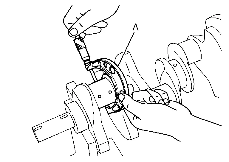
Measure the inner diameters (A) of each main bearing as shown.
Using suitable tool (A), measure the outer diameters of each crankshaft main journal as shown.
Calculate the main bearing clearance.
Main bearing clearance = (Main bearing inner diameter) - (Crankshaft journal diameter)
| Standard and Limit | : Refer to Main Bearing. |
-
If it exceeds the limit, replace the main bearing.
-
If clearance cannot be adjusted using any standard bearing grade, grind crankshaft journal and use an undersized bearing.
-
When grinding the crankshaft journal, confirm that the (L) dimension in the fillet role is more than the specified limit.
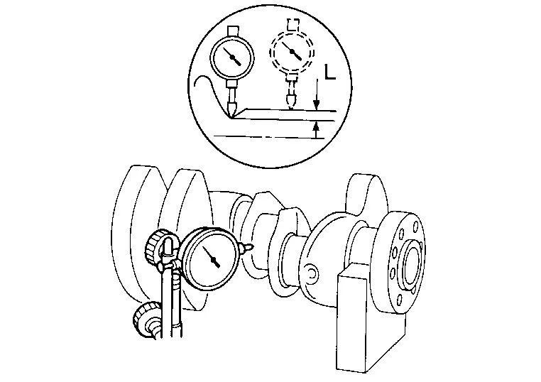
Limit : Refer to Cylinder Block.
If the crankshaft or the cylinder block is replaced with a new one, select thickness of the main bearings as follows:The grade number of each cylinder block main journal (B) is punched on the respective cylinder block. These numbers are punched in either Arabic or Roman numerals. If measured diameter is out of the grade punched, decide suitable grade from available main bearings.
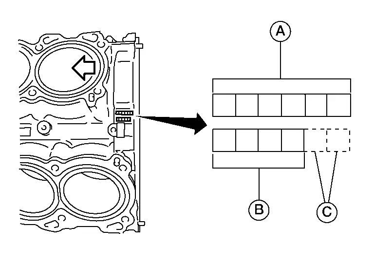
| (A) | : Cylinder bore grade |
| (C) | : Management code |
 |
: Engine front |
| (B) | : Crankshaft pin journal grade |
| (C) | : Production mark area |
| (A) | : Mark |
| (B) | : Cylinder block bearing housing inner diameter |
| (C) | : Crankshaft main journal diameter |
| (D) | : Journal diameter [Unit: mm (in)] |
| (E) | : Bore diameter [Unit: mm (in)] |
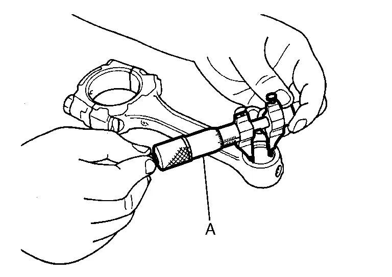
Connecting Rod Bearing (Big End)
Install connecting rod bearings (2) to connecting rod (3) and connecting rod bearings cap (1) and tighten connecting rod bolts. Refer to Disassembly and Assembly.
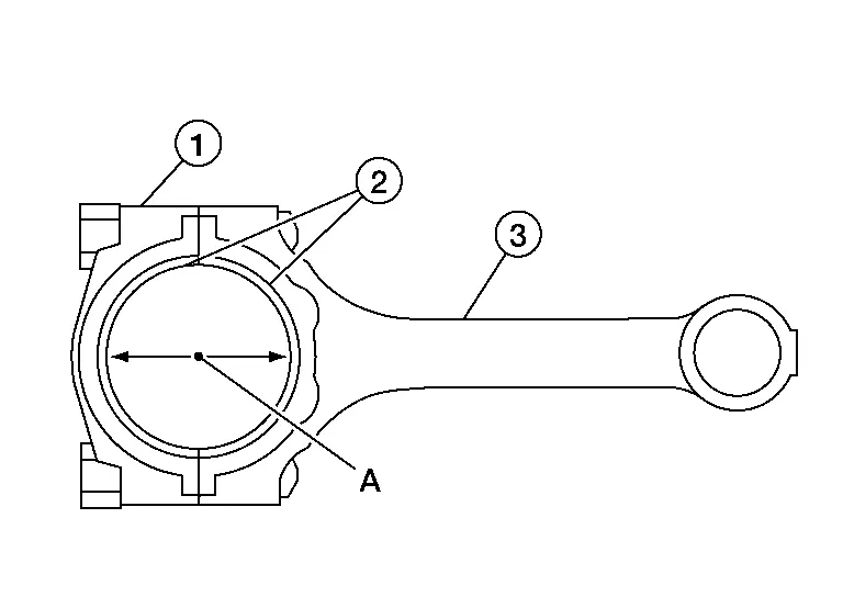
Measure the inner diameter (A) of each connecting rod (big end) as shown.
Using suitable tool (A), measure the outer diameter of each crankshaft pin journal.
Calculate the connecting rod bearing clearance.
(Bearing oil clearance) = (Connecting rod bearing inner diameter) - (Crankshaft pin journal diameter)
| Standard and Limit | : Refer to Connecting Rod Bearing. |
If the calculated clearance exceeds the specified limit, replace the bearings.
If the clearance cannot be adjusted within the standard of any bearing, grind the crankshaft journal and use undersized bearings.
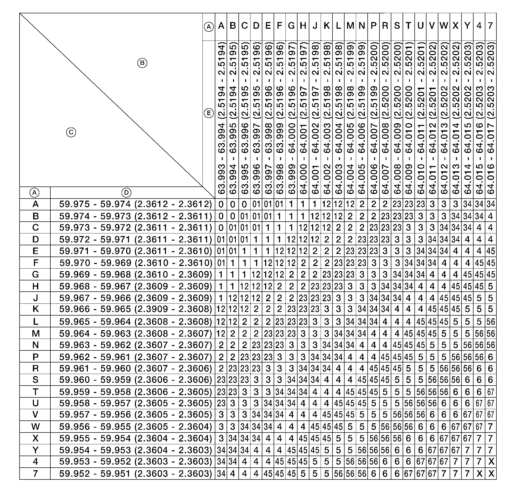
If the crankshaft is replaced with a new one, select the connecting rod bearings according to the following table:

| (A) | : Crankshaft main journal grade |
| (B) | : Crankshaft pin journal grade |
| (C) | : Production mark area |
Connecting Rod Bearing Grade Number (Identification Color)
| Crankshaft pin journal grade number | Connecting rod bearing grade number |
|---|---|
| 0 | 0 (black-black) |
| 1 | 1 (brown-brown) |
| 2 | 2 (green-green) |
These numbers are punched in either Arabic or Roman numerals.
Method B (Using Plastigage)
-
Remove engine oil and dust on the crankshaft pin and the surfaces of each bearing completely.
-
Cut a Plastigage slightly shorter than the bearing width, and place it in crankshaft axial direction, avoiding oil holes.
-
Install the connecting rod bearings to the connecting rod cap, and tighten the connecting rod bolts to the specified torque. Refer to Disassembly and Assembly.
CAUTION:
Do not rotate the crankshaft.
-
Remove the connecting rod cap and bearings, and using the scale on the Plastigage bag, measure the Plastigage width.
 NOTE:
NOTE:
The procedure when the measured value exceeds the repair limit is same as that described in "Method A (Using Bore Gauge and Micrometer)".
OIL JET
-
Check nozzle for deformation and damage.
-
Blow compressed air from nozzle, and check for clogs.
-
If it is not operating properly, replace oil jet.

Nissan Pathfinder (R53) 2022-2026 Service Manual
Contact Us
Nissan Pathfinder Info Center
Email: info@nipathfinder.com
Phone: +1 (800) 123-4567
Address: 123 Pathfinder Blvd, Nashville, TN 37214, USA
Working Hours: Mon–Fri, 9:00 AM – 5:00 PM (EST)
