Nissan Pathfinder: Engine Mechanical - Removal and Installation
- Engine Room Cover
- Air Cleaner and Air Duct
- Intake Manifold Collector
- Exhaust Manifold and Three Way Catalyst ➤
- Oil Pan ➤
- Intake Manifold
- Ignition Coil
- Rocker Cover ➤
- High Pressure Fuel Pump and Fuel Hose
- Fuel Injector and Fuel Tube ➤
- Valve Timing Control ➤
- Front Timing Chain Case ➤
- Timing Chain ➤
- Rear Timing Chain Case ➤
- Camshaft ➤
- Oil Seal
- Cylinder Head ➤
- Engine Mount
- Drive Plate
Engine Room Cover Nissan Pathfinder 2022
Exploded View
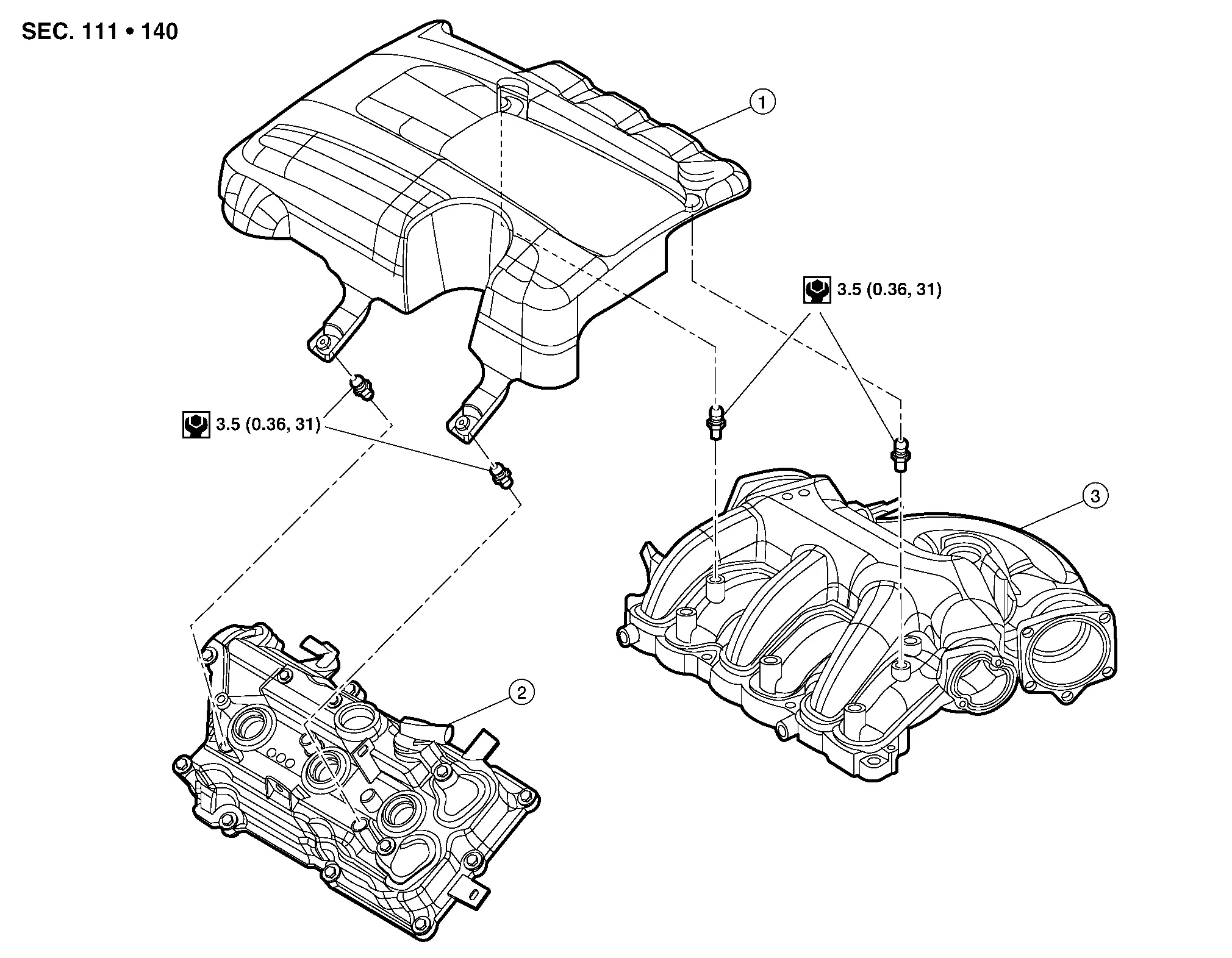
| 1. | Engine room cover | 2. | Rocker cover (bank 2) | 3. | Intake manifold collector |
Removal and Installation
CAUTION:
Do not damage or scratch engine room cover when installing or removing.
REMOVAL
Remove front air duct. Refer to Removal and Installation.
Lift up on engine room cover to disengage clips.
Remove engine room cover.
INSTALLATION
Installation is in the reverse order of removal.
Air Cleaner and Air Duct Nissan Pathfinder SUV
Exploded View
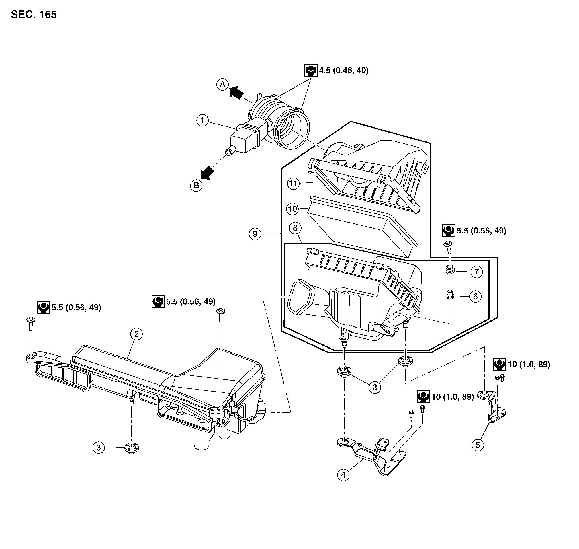
| 1. | Air duct hose and resonator assembly | 2. | Front air duct | 3. | Grommet |
| 4. | Air cleaner case mounting bracket | 5. | Bracket | 6. | Retainer |
| 7. | Mounting rubber | 8. | Air cleaner case (lower) | 9. | Air cleaner assembly |
| 10. | Air cleaner filter | 11. | Air cleaner case (upper) | A. | To electric throttle control actuator. Refer to Exploded View. |
| B. | To rocker cover (bank 1). Refer to Exploded View. |
Removal and Installation
REMOVAL
Remove front air duct.
Disconnect the tube clamp at the electric throttle control actuator and at the air duct hose and resonator assembly.
Disconnect the blow-by hose from air duct hose and resonator assembly.
Remove air duct hose and resonator assembly.
Disconnect the harness connector from mass air flow sensor and release harness retainer from air cleaner case (upper).
Release clips and remove the air cleaner case (upper).
Remove bolt and remove the air cleaner case (lower) and air cleaner filter.
Remove mass air flow sensor from air cleaner case (upper) (if necessary).
CAUTION:
Handle mass air flow sensor with care.
-
Do not shock it.
-
Do not disassemble it.
-
Do not touch its sensor.
Remove air cleaner filter from air cleaner case (lower) (if necessary).
INSPECTION AFTER REMOVAL
Inspect air cleaner case (upper), air cleaner case (lower), front air duct, air duct and resonator assembly for cracks or tears. Replace as necessary.
INSTALLATION
Installation is in the reverse order of removal.
 NOTE:
NOTE:
When installing air duct hose and resonator assembly, align mating marks and insert until air duct hose and resonator assembly touches stoppers on electronic throttle body actuator and air cleaner case (upper).
Intake Manifold Collector Nissan Pathfinder Fifth generation
Exploded View
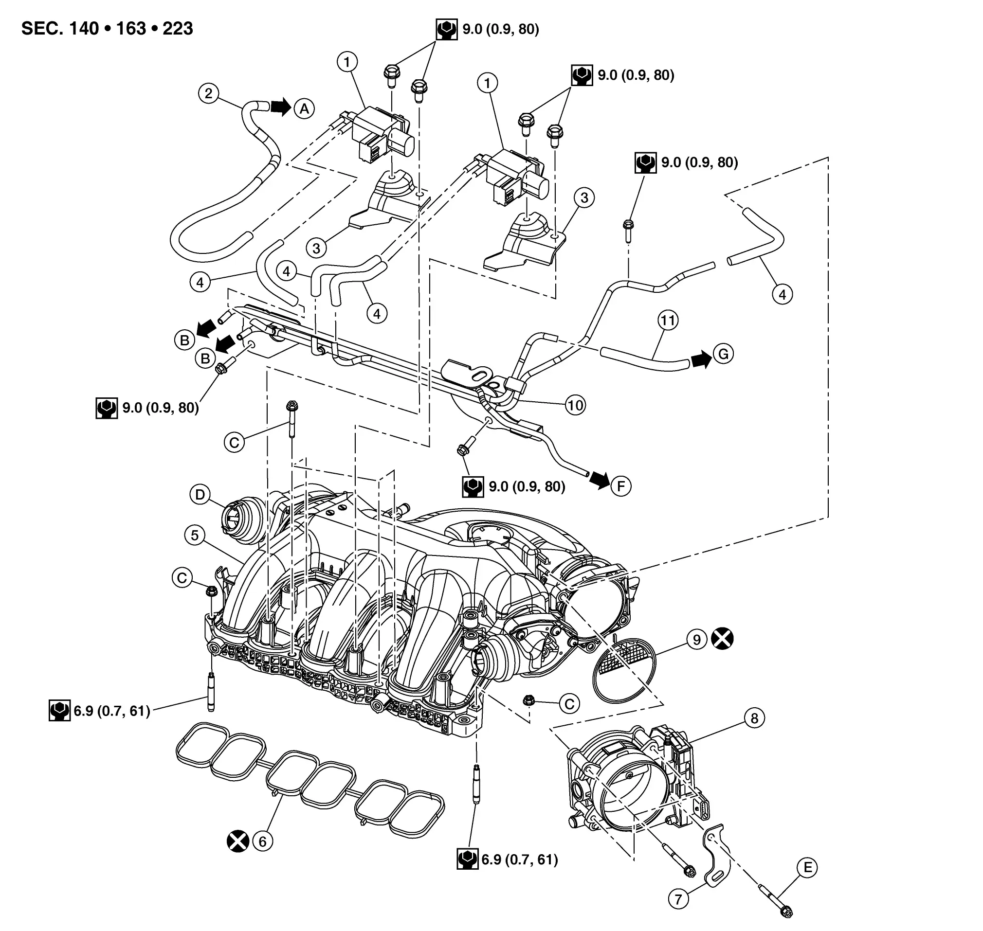
| 1. | VIAS control solenoid valve | 2. | Vacuum hose 1 | 3. | VIAS control solenoid valve bracket |
| 4. | Vacuum hose 2 | 5. | Intake manifold collector | 6. | Intake manifold collector gasket |
| 7. | Harness bracket | 8. | Electronic throttle control actuator | 9. | Electronic throttle control actuator gasket |
| 10. | Vacuum tube assembly | 11. | Vacuum hose 3 | A. | To power valve actuator 1. Refer to Component Parts Location. |
| B. | To electronic controlled engine mount control solenoid valve. Refer to Component Parts Location. | C. | Refer to Removal and Installation. | D. | Power valve actuator 1 |
| E. | Refer to Removal and Installation. | F. | To engine mount (FR). Refer to Exploded View. | G. | To power valve actuator 2. Refer to Component Parts Location. |
Removal and Installation
REMOVAL
WARNING:
Do not drain the engine coolant when the engine is hot to avoid the danger of being scalded.
CAUTION:
-
Do not remove power valves.
-
Cover engine openings to avoid the entry of any foreign material.
 NOTE:
NOTE:
When removing components such as hoses, tubes/lines, etc., cap or plug openings to prevent fluid from spilling.
Disconnect the negative battery terminal. Refer to Battery Disconnect.
Remove the cowl top cover and the cowl top extension. Refer to Removal and Installation.
Remove engine room cover (if equipped). Refer to Removal and Installation.
Remove the air cleaner case (upper), air cleaner case (lower), and air duct and resonator assembly. Refer to Removal and Installation.
Disconnect the engine mount (FR) vacuum hose, brake booster vacuum hose and electronic controlled engine mount control solenoid valve vacuum hoses from intake manifold collector.
Disconnect the harness connector from electronic controlled engine mount control solenoid valve. Refer to Component Parts Location.
Disconnect the engine mount insulator (front) vacuum hose.
Disconnect the harness connector from VIAS control solenoid valve 1 and VIAS control solenoid valve 2.
Disconnect the PCV hose from intake manifold collector.
Disconnect the EVAP canister purge volume control solenoid valve hose.
Disconnect the harness connector from electronic throttle control actuator and remove retainer from harness bracket.
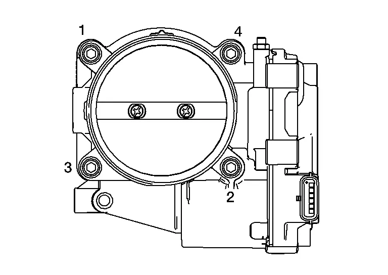
Loosen bolts in reverse of the sequence shown and remove the electric throttle control actuator (if necessary).
CAUTION:
-
Handle carefully to avoid any shock to the electric throttle control actuator.
-
Do not disassemble electric throttle control actuator.
-
Do not reuse electric throttle control actuator gasket (if removed).
Remove the VIAS control solenoid valve (if necessary).
Remove the EVAP canister purge volume control solenoid valve. Refer to Exploded View.
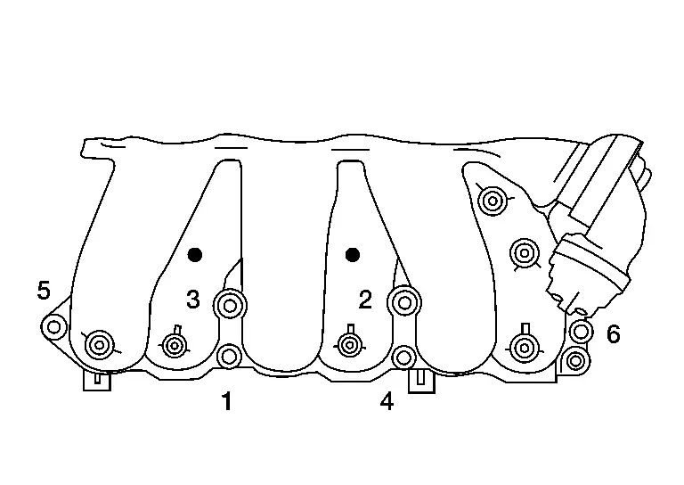
Loosen the intake manifold collector bolts and nuts in reverse of the sequence shown and then remove the intake manifold collector and gasket.
CAUTION:
Do not reuse intake manifold collector gasket.
INSTALLATION
Installation is in the reverse order of removal.
-
Tighten intake manifold collector bolts and nuts in the order as shown.

CAUTION:
Do not reuse gasket.
Bolts and nuts : 11.0 N·m (1.1 kg-m, 8 ft-lb) -
Tighten electric throttle control actuator bolts in the order shown.

CAUTION:
Do not reuse electric throttle control actuator gasket.
Bolts : 8.4 N·m (0.86 kg-m, 74 in-lb)
 NOTE:
NOTE:
After installation, perform the following:
-
Perform the ″Throttle Valve Closed Position Learning″ when harness connector of the electric throttle control actuator is disconnected. Refer to Description.
-
Perform the ″Idle Air Volume Learning″ when the electric throttle control actuator is replaced. Refer to Description.
Exhaust Manifold and Three Way Catalyst ➤ Nissan Pathfinder 2026
Oil Pan ➤ Nissan Pathfinder 5th Gen
Intake Manifold Nissan Pathfinder Fifth generation
Exploded View
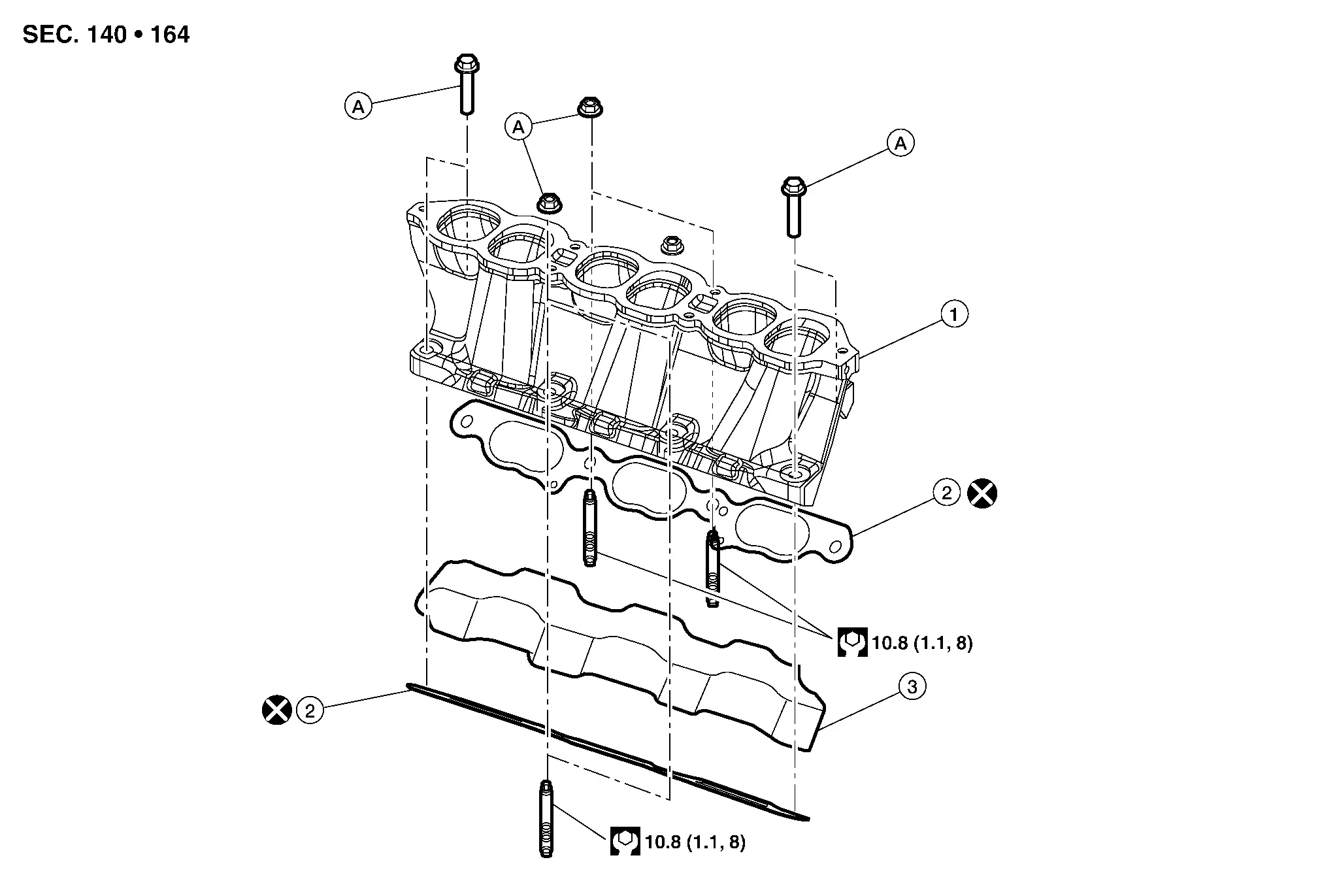
| 1. | Intake manifold | 2. | Intake manifold gasket | 3. | Insulator |
| A. | Refer to INSTALLATION. |
Removal and Installation
REMOVAL
Remove intake manifold collector. Refer to Removal and Installation.
Loosen intake manifold nuts and bolts in reverse of the sequence shown.

 |
: Engine front |
Remove intake manifold and intake manifold gasket.
CAUTION:
Do not reuse intake manifold gasket.
Remove intake manifold studs (if necessary).
INSPECTION AFTER REMOVAL
Surface Distortion
-
Using suitable tool (A) and suitable tool (B), inspect the surface distortion of the intake manifold. Refer to Intake Manifold.
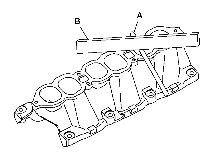
Standard : 0.1 mm (0.004 in)
INSTALLATION
Installation is in the reverse order of removal.
CAUTION:
-
Do not reuse gasket.
-
Install the gaskets with the painted surface facing the intake manifold side.
-
Install intake manifold studs (if removed) and tighten to specification.
Intake manifold studs : 10.8 N·m (1.1 kg-m, 8 ft-lb) -
Install intake manifold bolts and nuts and tighten to the specified torque in the sequence shown.
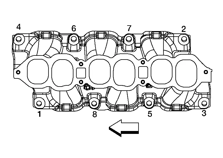
Step 1 : 7.4 N·m (0.75 kg-m, 65 in-lb) Step 2 : 25.5 N·m (2.6 kg-m, 19 ft-lb) 
: Engine front
Ignition Coil Nissan Pathfinder 5th Gen
Exploded View
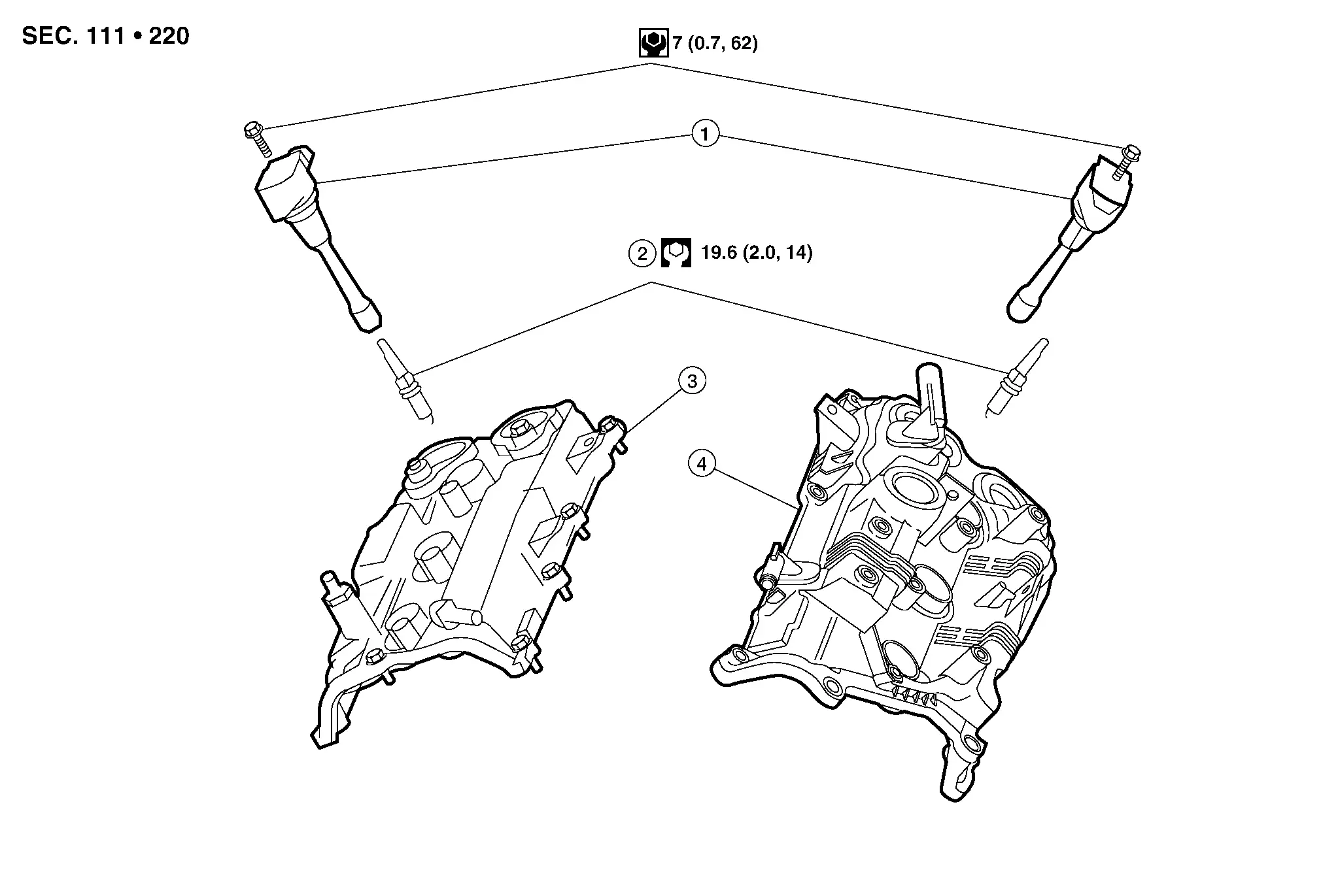
| 1. | Ignition coil | 2. | Spark plug | 3. | Rocker cover (Bank 1) |
| 4. | Rocker cover (Bank 2) |
Removal and Installation (Bank 2)
REMOVAL
Remove engine room cover. Refer to Removal and Installation.
Disconnect the harness connector from ignition coil.
Remove the ignition coil.
CAUTION:
Do not shock ignition coil.
INSTALLATION
Installation is in the reverse order of removal.
Removal and Installation (Bank 1)
REMOVAL
Remove the intake manifold collector. Refer to Removal and Installation.
Disconnect the harness connector from ignition coil.
Remove the ignition coil.
CAUTION:
Do not shock ignition coil.
INSTALLATION
Installation is in the reverse order of removal.
Rocker Cover ➤ Nissan Pathfinder 2022
High Pressure Fuel Pump and Fuel Hose Nissan Pathfinder 5th Gen
Exploded View
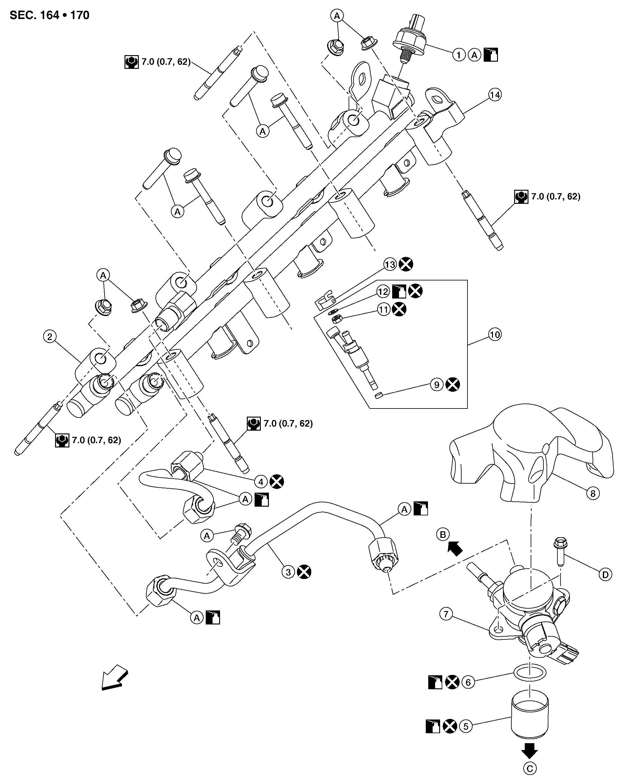
| 1. | Fuel rail pressure sensor | 2. | Fuel rail (bank 1) | 3. | High pressure fuel tube (pump side) |
| 4. | High pressure fuel tube (bank side) | 5. | Lifter | 6. | O-ring |
| 7. | High pressure fuel pump | 8. | High pressure fuel pump insulator | 9. | Seal ring |
| 10. | Injector | 11. | Backup ring | 12. | O-ring (green) |
| 13. | Injector holder | 14. | Fuel rail (bank 2) | A. | Refer to Removal and Installation. |
| B. | To fuel feed hose | C. | To camshaft bracket no. 1. Refer to Exploded View. | D. | Refer to Removal and Installation. |
 |
Engine front |
Removal and Installation
REMOVAL
WARNING:
-
Be sure to read Precaution for Handling High Pressure Fuel System when working on the high pressure fuel system.
-
Put a “CAUTION: FLAMMABLE” sign in the workshop.
-
Be sure to work in a well ventilated area and furnish workshop with a CO2 fire extinguisher.
-
Do not smoke while servicing fuel system. Keep open flames and sparks away from the work area.
CAUTION:
-
Do not remove or disassemble parts unless instructed as shown in the figure.
-
Be sure to follow the tightening instruction to avoid fuel leaks.
 NOTE:
NOTE:
When removing components such as hoses, tubes/lines, etc., cap or plug openings to prevent fluid from spilling.
Release fuel pressure. Refer to Work Procedure.
Remove intake manifold. Refer to Removal and Installation.
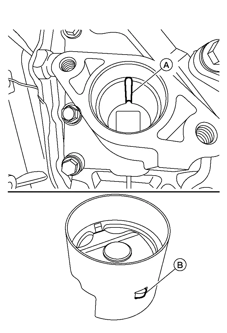
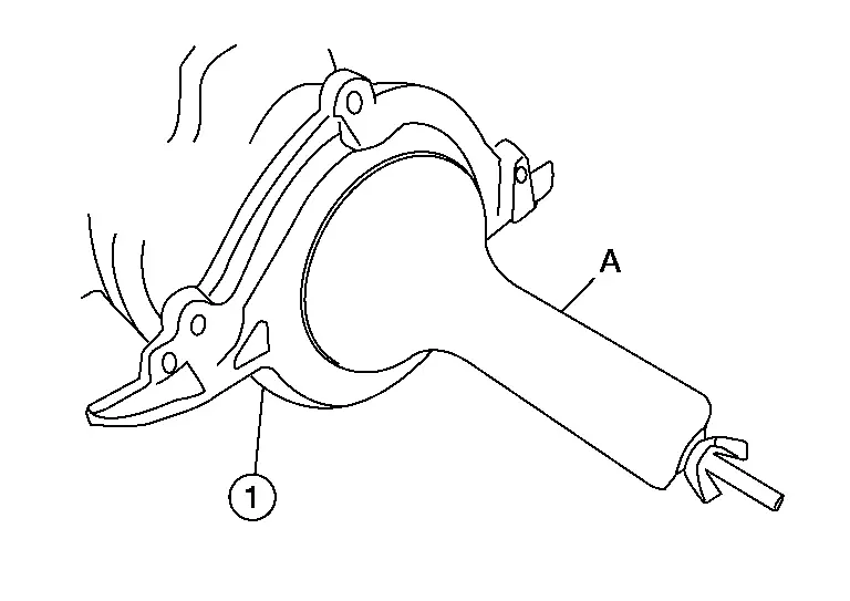
Remove bolts (A) and remove high pressure fuel pump cover (1).
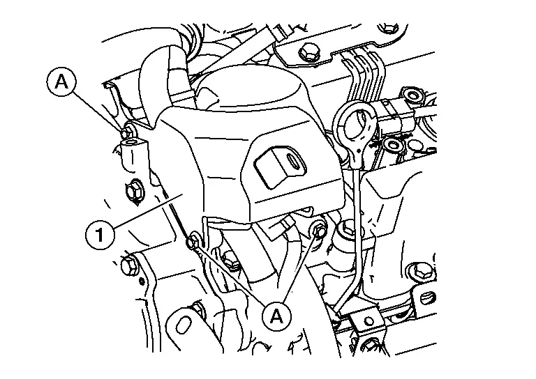
Remove high pressure fuel pump insulator.
Release clip (A) and disconnect fuel feed hose (1) from high pressure fuel pump (2).
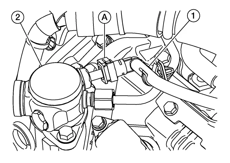
Disengage fuel feed hose from clip and reposition.
Remove insulator. Refer to Exploded View.
Remove high pressure fuel tube (pump side).
CAUTION:
Do not reuse high pressure fuel tube (pump side).
Disconnect harness connector from high pressure fuel pump.
Remove high pressure fuel pump bolts while alternating sides frequently and remove high pressure fuel pump and lifter.
CAUTION:
-
Do not reuse O-ring.
-
Do not disassemble plunger on bottom of high pressure fuel pump.
INSTALLATION
Install O-ring to high pressure fuel pump.
CAUTION:
-
Do not reuse O-ring.
-
Handle O-ring with bare hands. Do not wear gloves.
-
Lubricate O-ring with new engine oil.
-
Check that O-ring and its mating part are free of foreign material.
-
When installing O-ring, be careful not to scratch it with suitable tool or fingernails. Also be careful not to twist or stretch O-ring. If O-ring was stretched while it was being attached, do not insert it immediately into front cover.
-
Insert new O-ring straight into high pressure fuel pump. Do not decenter or twist it.
Rotate engine clockwise and visually check for bottom dead center of high pressure fuel pump lobe on camshaft.
Apply clean engine oil to high pressure fuel pump bore.
When installing lifter, note the orientation of lifter protrusion (B) and cutout in No. 1 camshaft bracket [bank 2 (A)] should be aligned.
Install high pressure fuel pump and tighten the bolts using the following procedure:
CAUTION:
-
Do not reuse O-ring.
-
Do not disassemble plunger on bottom of high pressure fuel pump.
 NOTE:
NOTE:
Apply clean engine oil to lifter contact surface and O-ring.
Tighten bolts one revolution while alternating sides until high pressure fuel pump is mated to No. 1 camshaft bracket. Tighten bolts to the specified torque.| High pressure fuel pump bolts | : 26.5 N·m (2.7 kg-m, 20 ft-lb) |
Connect harness connector to high pressure fuel pump.
Install high pressure fuel tube (pump side) using the following procedure:
CAUTION:
-
Do not reuse high pressure fuel tube (pump side).
-
Do not apply engine oil to threads of high pressure fuel pump, fuel rail (bank 1) or high pressure fuel tube (pump side).
-
Do not use high pressure fuel tube (pump side) if its terminal tip is damaged.
-
Check that there is no foreign material on the high pressure fuel tube (pump side) flare nipple or flare nuts.
-
If scratches or damage are visible on flare nipple of high pressure fuel tube, do not use it.
-
If flare nut is difficult to tighten, inspect threads for damage and replace if damage is present.
CAUTION:
When hand tightening the flare nuts, insert them so that they are aligned with the center of the pipe.
 NOTE:
NOTE:
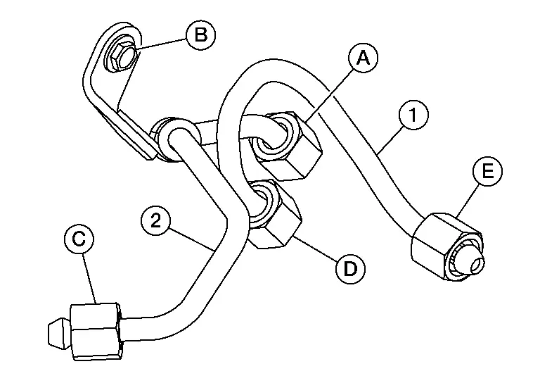
Should be no gap between high pressure fuel tube, high pressure fuel tube bracket and rear timing chain case.
| (1) | : High pressure fuel tube (bank side) |
| (D) | : High pressure fuel tube (bank side) flare nut |
| (E) | : High pressure fuel tube (bank side) flare nut |
| Flare nut | : 15 N·m (1.5 kg-m, 11 ft-lb) |
| Flare nut | : 23.0 N·m (2.3 kg-m, 17 ft-lb) |
| Bolt | : 13.5 N·m (1.4 kg-m, 10 ft-lb) |
Installation of the remaining components is in the reverse order of removal.
-
Check for fuel leaks. Refer to Inspection.
CAUTION:
After checking fuel leaks, maintain ten minutes of idling to bleed the fuel line.
-
Tighten high pressure fuel pump cover bolts to the specified torque in the sequence shown.
High pressure fuel pump cover bolts : 11.0 N·m (1.1 kg-m, 8 ft-lb) 
: Engine front
Inspection
Check for Fuel Leaks
-
Place ignition switch in the “ON” position (with the engine stopped). With fuel pressure applied to fuel piping, check that there is no fuel leaks at connection points.
 NOTE:
NOTE:
Use mirrors for checking at points out of clear sight.
-
Start the engine. With engine speed increased, check again that there is no fuel leaks at connection points.
CAUTION:
Do not touch the engine immediately after it is stopped because the engine is extremely hot.
Fuel Injector and Fuel Tube ➤ Nissan Pathfinder Fifth generation
Valve Timing Control ➤ Nissan Pathfinder Fifth generation
Front Timing Chain Case ➤ Nissan Pathfinder 5th Gen
Timing Chain ➤ Nissan Pathfinder 5th Gen
Rear Timing Chain Case ➤ Nissan Pathfinder 5th Gen
Camshaft ➤ Nissan Pathfinder Fifth generation
Oil Seal Nissan Pathfinder R53
Removal and Installation of Valve Oil Seal
REMOVAL
Turn crankshaft until the cylinder requiring new oil seals is at TDC. This will prevent valve from dropping into cylinder.
CAUTION:
be careful to avoid scarring the front cover with the timing chain.
Remove camshaft relating to valve oil seal to be removed. Refer to Removal and Installation.
Remove valve lifters. Refer to Disassembly and Assembly.
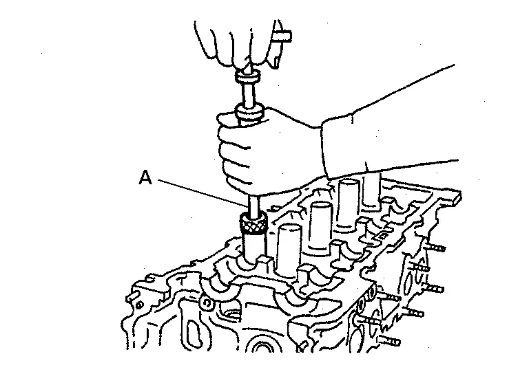
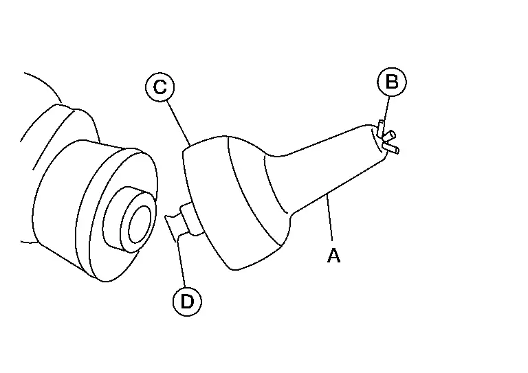
Compress the valve spring with suitable tool (A), (B) and (C) and remove the valve collet with a suitable magnetic tool.
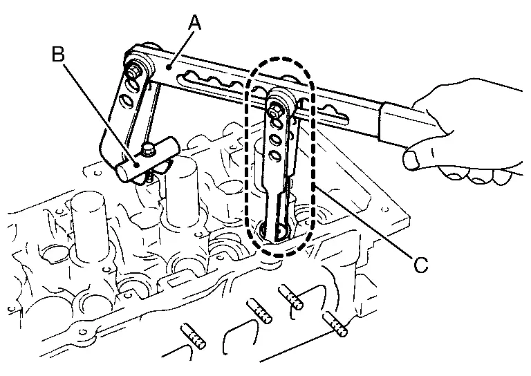
CAUTION:
Do not damage valve lifter bore.
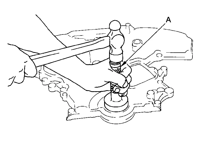
Remove valve oil seal using suitable tool (A).
INSTALLATION
Apply new engine oil to new valve oil seal joint surface and seal lip.
Press in valve oil seal to height (H) using suitable tool (A) to specified height.
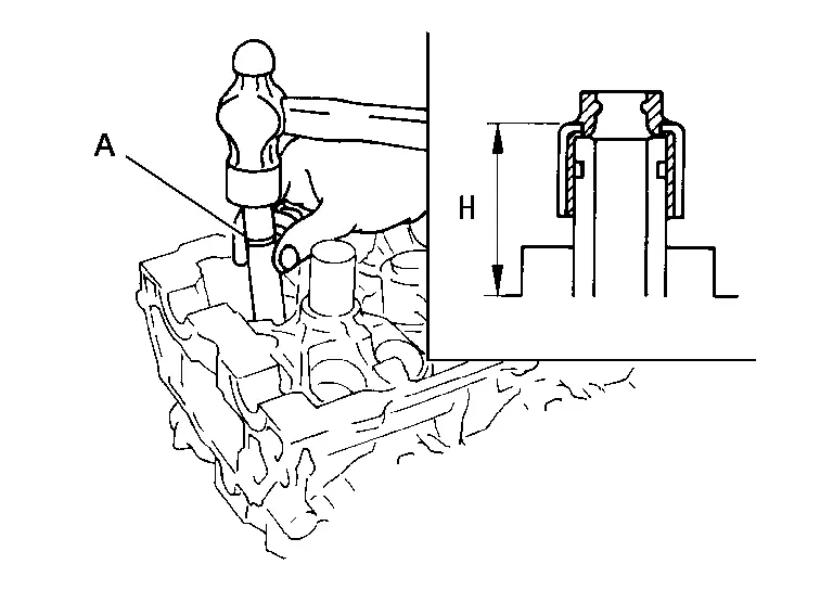
 NOTE:
NOTE:
Dimension (H): height measured before valve spring seat installation.
| Intake and exhaust (H) | : Refer to Cylinder Head. |
Installation of the remaining components is in the reverse order of removal.
Removal and Installation of Front Oil Seal
REMOVAL
Remove drive belt. Refer to Removal and Installation.
Secure the crankshaft pulley using a suitable tool.
Remove the crankshaft pulley as follows:Loosen crankshaft pulley bolt and locate bolt seating surface at 10 mm (0.39 in) from its original position. Position a pulley puller at recess hole of crankshaft pulley to remove crankshaft pulley.
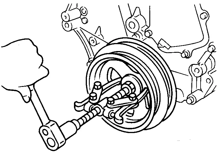
CAUTION:
Do not use a puller claw on the outer diameter of the crankshaft pulley.
Remove front oil seal from front cover using a suitable tool.
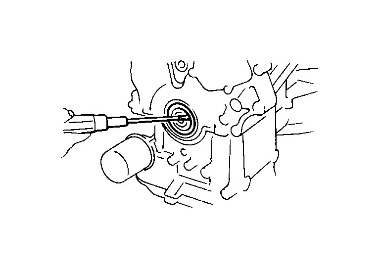
CAUTION:
Do not damage front cover or crankshaft.
INSTALLATION
Apply new engine oil to new oil seal and install.
-
Install new oil seal in the direction as shown.
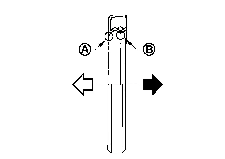
(A) : Dust seal lip (B) : Oil seal lip 
: Engine outside 
: Engine inside
CAUTION:
-
Do not reuse front oil seal.
-
Press fit straight and avoid causing burrs or tilting the oil seal.
-
Press-fit oil seal until it becomes flush with the timing chain case end face, using suitable tool (A).
-
Make sure the garter spring in the oil seal is in position and seal lip is not inverted.
Install crankshaft pulley and tighten the bolt using the following procedure:
-
Apply a suitable anti-seize lubricant to the crankshaft pulley bolt flange and crankshaft pulley bolt threads.
-
Secure the crankshaft pulley using a suitable tool.
-
Tighten crankshaft pulley bolt to the specified torque and then specified angle using Tool.
CAUTION:
-
Do not damage the front oil seal when inserting crankshaft pulley.
-
Use only brass or plastic hammer if tapping on the crankshaft pulley.
-
Do not hammer on pulley grooves.
| Step 1 | : 90 N·m (9.2 kg-m, 66 ft-lb) |
| Step 2 | : 84° - 90° degrees clockwise |
| Tool number | : KV10112100 (BT-8653-A) |
Installation of the remaining components is in the reverse order of removal.
Removal and Installation of Rear Oil Seal
REMOVAL
Remove the upper oil pan. Refer to Removal and Installation (Upper Oil Pan).
Remove rear oil seal retainer using Tool.
| Tool Number | : KV10111100 (NI-37228) |
CAUTION:
-
Do not damage mating surface.
-
If rear oil retainer is removed, replace it with a new one.
 NOTE:
NOTE:
Rear oil seal and retainer form a single part and are replaced as an assembly.
INSTALLATION
Remove old liquid gasket material from mating surface of cylinder block and oil pan using a suitable scraper.
Install the rear oil seal retainer using Tool (A).
CAUTION:
Do not reuse rear oil seal retainer.
| Tool number (A) | : — (NI-47128) |
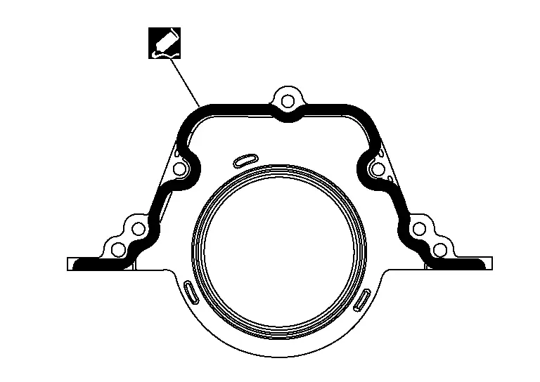
Use Genuine Silicone RTV Sealant or equivalent. Refer to Recommended Chemical Products and Sealants.
CAUTION:
-
Installation should be done within 5 minutes after applying liquid gasket.
-
Do not fill the engine with engine oil for at least 30 minutes after the components are installed to allow the liquid gasket to cure.
| Rear oil seal retainer bolts | : 8.8 N·m (0.9 kg-m, 78 in-lb) |
Installation of the remaining components is in the reverse order of removal.
CAUTION:
-
When replacing an engine or transaxle you must make sure the dowels are installed correctly during re-assembly.
-
Improper alignment caused by missing dowels may cause vibration, engine oil leaks or breakage of drivetrain components.
Cylinder Head ➤ Nissan Pathfinder 2026
Engine Mount Nissan Pathfinder 5th Gen
Engine Mount (front)
Removal and Installation
WARNING:
-
Situate the vehicle on a flat and solid surface.
-
Place chocks at front and back of rear wheels.
CAUTION:
-
Always work safely.
-
Do not start work until the engine and exhaust system are cooled completely.
-
Refer to the applicable sections for warnings, cautions, notes, and instructions if necessary procedures are not included in this section.
 NOTE:
NOTE:
-
When removing components such as hoses, tubes/lines, etc., cap or plug openings to prevent fluid from spilling.
-
For exploded view, Refer to Exploded View.
REMOVAL
Remove the air cleaner case (upper), air cleaner case (lower), front air duct, and air duct hose and resonator assembly. Refer to Removal and Installation.
Remove the battery and battery tray assembly. Refer to Removal and Installation.
Remove the front under cover. Refer to Removal and Installation.
Remove the front fender protector side covers (RH/LH). Refer to Exploded View.
Partially remove the fender protectors (RH/LH). Refer to Exploded View.
Remove the radiator assembly. Refer to Removal and Installation.
Remove the engine cooling fan shroud and motor assembly. Refer to Removal and Installation.
Remove the exhaust manifold heat shield (LH). Refer to Exploded View.
Support the engine with a suitable tool.
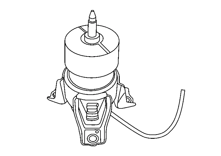
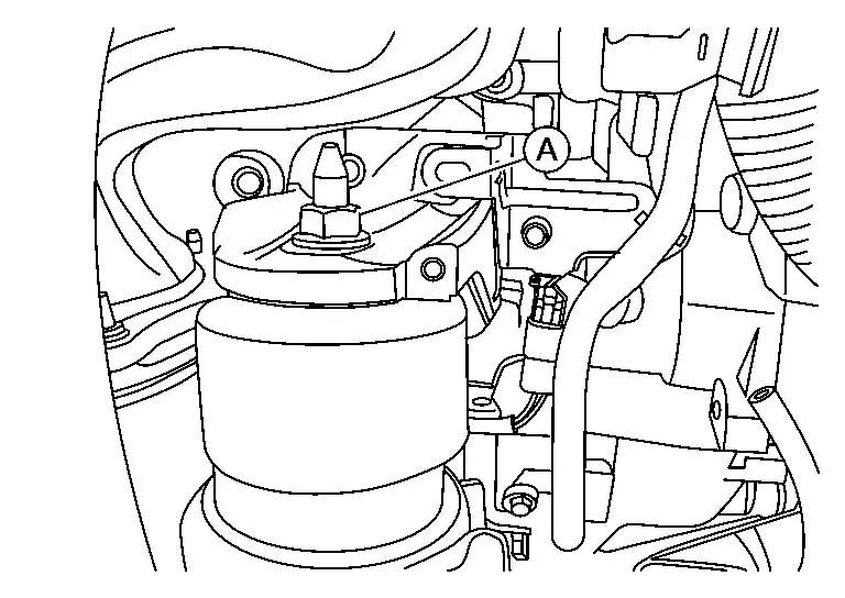
Disconnect the engine mount insulator (front) vacuum hose.
Remove the engine mount insulator (front) nut (A).

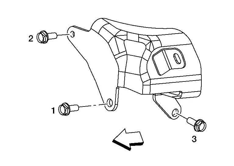
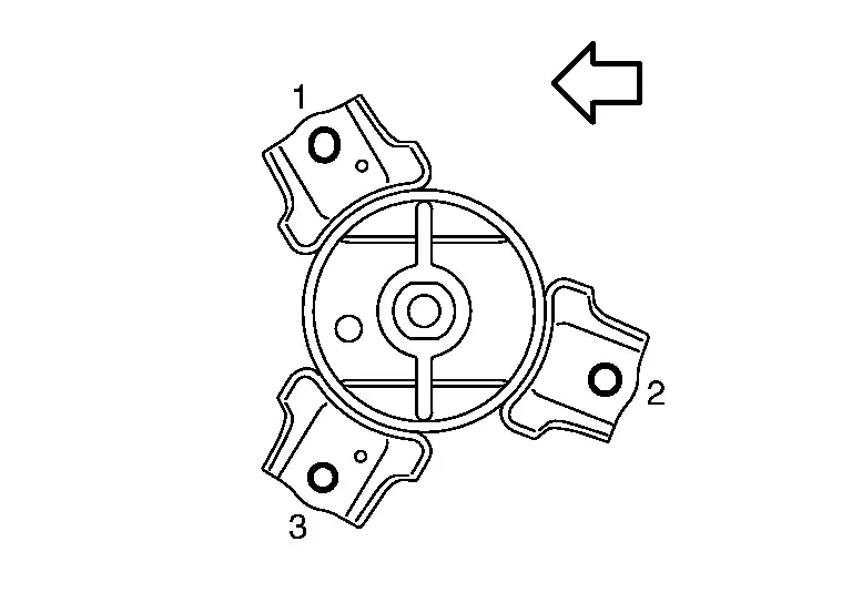
Loosen the engine mount bracket (front) bolts in reverse of the order shown.

 |
: Engine front |
Remove the engine mount bracket (front).
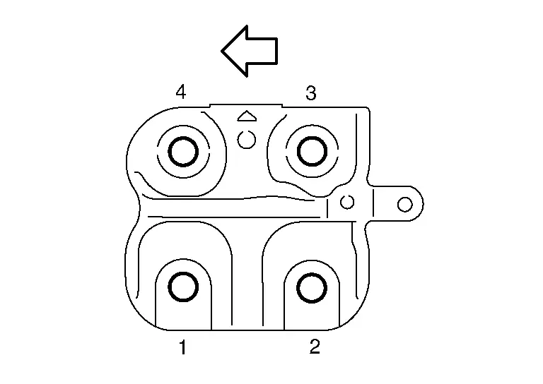
Remove the engine mount insulator (front) bolts in the reverse order as shown.

 |
: Front |
Remove the engine mount insulator (front).

INSTALLATION
CAUTION:
-
Do not damage or spill engine oil on the engine mount insulator (front).
-
Check engine mount insulator (front) is seated properly before tightening.
Install the engine mount insulator (front).
Install the engine mount insulator (front) bolts and tighten to specification in the order shown.
 |
: Front |
| Engine mount insulator (front) bolts | : 62.0 N·m (6.3 kg-m, 46 ft-lb) |
Install the engine mount bracket (front) to the engine block.
Tighten the engine mount bracket (front) bolts to specification in the order shown.
 |
: Engine front |
| Engine mount bracket (front) bolts | : 62.0 N·m (6.3 kg-m, 46 ft-lb) |
Install the engine mount insulator (front) nut (A) and tighten to specification.
| Engine mount insulator (front) nut | : 105 N·m (11 kg-m, 77 ft-lb) |
Installation of the remaining components is in the reverse order of removal.
Drive Plate Nissan Pathfinder 2026
Removal and Installation
For exploded view, refer to Exploded View.
REMOVAL
Remove the engine and transmission assembly and separate the engine from the transmission. Refer to Removal and Installation.
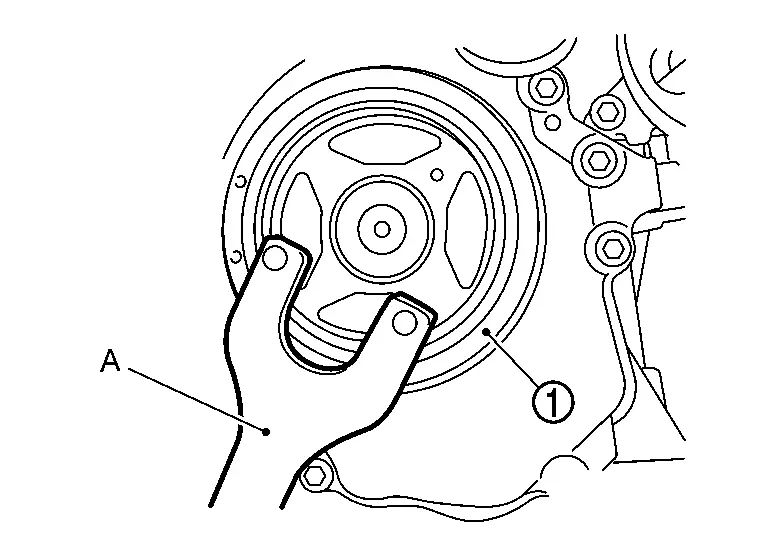
Remove the drive plate using the following procedure:Before removing the drive plate, inspect the drive plate runout is within specification. Refer to Inspection. Secure the crankshaft pulley (1) with a suitable tool (A).
CAUTION:
-
Do not disassemble drive plate.
-
Do not place drive plate with signal plate facing down.
-
When handling drive plate, take care not to damage or scratch drive plate and signal plate.
-
Handle drive plate in manner that prevents signal plate from becoming magnetized.
INSTALLATION
Install the drive plate and drive plate reinforcement.
CAUTION:
-
Do not disassemble drive plate.
-
Do not place drive plate with signal plate facing down.
-
When handling drive plate, take care not to damage or scratch drive plate and signal plate.
-
Handle drive plate in manner that prevents signal plate from becoming magnetized.
 NOTE:
NOTE:
-
Align hole in drive plate mounting surface with dowel on back of crankshaft when installing drive plate.
-
Install drive plate reinforcement with radius towards drive plate.
Hand tighten drive plate bolts in a diagonal pattern over several steps.
Secure the crankshaft pulley with a suitable tool, then and tighten drive plate bolts in a diagonal pattern over several steps.
Installation of the remaining components is in the reverse order of removal.
Inspection
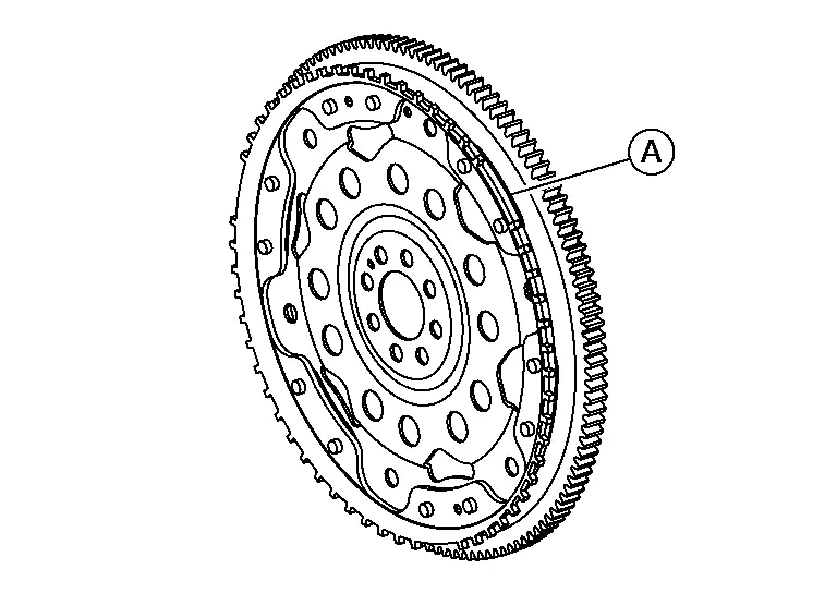
Use a suitable tool to measure the runout (Total Indicator Reading) on torque converter mating surface (A).
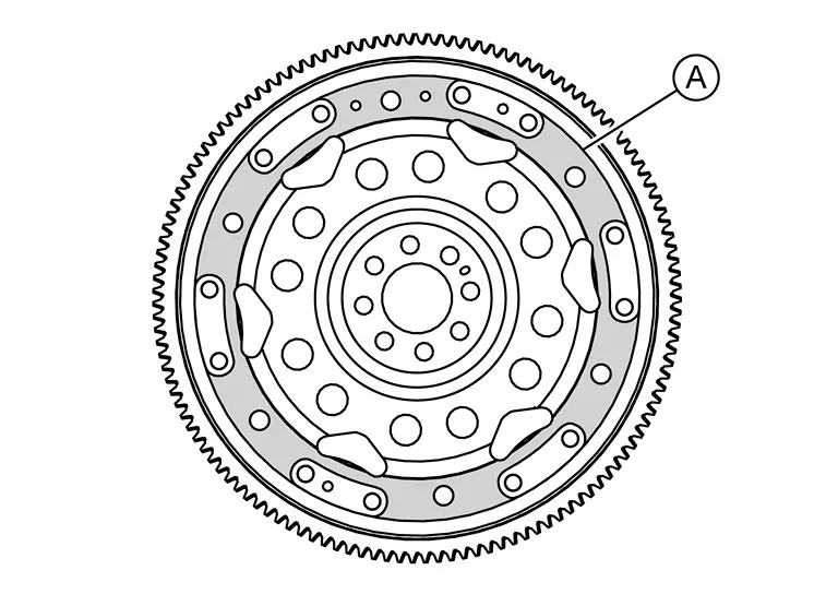
| Drive plate torque converter surface | : Refer to Drive Plate. |
| Ring gear | : Refer to Drive Plate. |
CAUTION:
-
The signal plate is built into the drive assembly. Be careful not to damage the signal plate, particularly the teeth.
-
Check the drive plate and signal plate for deformation or cracks.
-
Keep all magnetized objects away from the signal plate, particularly the teeth.

Nissan Pathfinder (R53) 2022-2026 Service Manual
Removal and Installation
- Engine Room Cover
- Air Cleaner and Air Duct
- Intake Manifold Collector
- Exhaust Manifold and Three Way Catalyst ➤
- Oil Pan ➤
- Intake Manifold
- Ignition Coil
- Rocker Cover ➤
- High Pressure Fuel Pump and Fuel Hose
- Fuel Injector and Fuel Tube ➤
- Valve Timing Control ➤
- Front Timing Chain Case ➤
- Timing Chain ➤
- Rear Timing Chain Case ➤
- Camshaft ➤
- Oil Seal
- Cylinder Head ➤
- Engine Mount
- Drive Plate
Contact Us
Nissan Pathfinder Info Center
Email: info@nipathfinder.com
Phone: +1 (800) 123-4567
Address: 123 Pathfinder Blvd, Nashville, TN 37214, USA
Working Hours: Mon–Fri, 9:00 AM – 5:00 PM (EST)
