Nissan Pathfinder: Removal and Installation - Cylinder Head ++
Exploded View
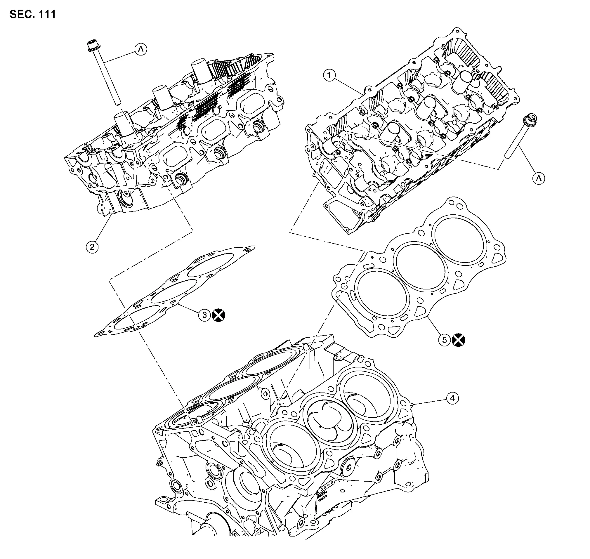
| 1. | Cylinder head (bank 2) | 2. | Cylinder head (bank 1) | 3. | Cylinder head (bank 1) gasket |
| 4. | Cylinder block | 5. | Cylinder head (bank 2) gasket | A. | Refer to Removal and Installation. |
Removal and Installation
REMOVAL
Remove the intake and exhaust camshafts. Refer to Removal and Installation.
If removing the cylinder head (bank 2), remove the exhaust manifold and three way catalyst (bank 2) using the following procedure:Disconnect the harness connector from the air fuel ratio (A/F) sensor (bank 2) and release the harness from retainer. Remove the air fuel ratio (A/F) sensor 1 (bank 2) using Tool. Refer to Exploded View.
CAUTION:
-
Do not damage air fuel ratio (A/F) 1 sensor (bank 2).
-
Discard any air fuel ratio (A/F) 1 sensor (bank 2) which has been dropped from a height of more than 0.5 m (19.7 in) onto a hard surface such as a concrete floor; replace with a new sensor.
| Tool | : KV991J0050 (NI-44626) |
CAUTION:
Do not reuse exhaust manifold cover (bank 2) bolts.
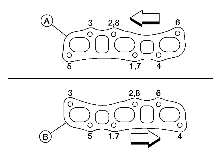
Disconnect the harness connector from the heated oxygen sensor (bank 2). Remove the support bracket (bank 2). Refer to Exploded View. Loosen and remove the exhaust manifold and three way catalyst nuts (bank 2) in reverse of the sequence shown.

 NOTE:
NOTE:
Number 7 and 8 are not applicable to removal.
| (A) | : Bank 2 |
| (B) | : Bank 1 |
 |
: Engine front |
CAUTION:
Do not reuse exhaust manifold gasket.
If removing the cylinder head (bank 1), remove the exhaust manifold and three way catalyst (bank 1) using the following procedure:Disconnect the harness connector from the air fuel ratio (A/F) sensor 1 (bank 1) and remove harness from retainer. Remove exhaust manifold (bank 1) cover. Refer to Exploded View. Disconnect the harness connector from the heated oxygen sensor 2 (bank 1) and remove harness from retainers. Remove bolt securing support bracket (bank 1) to the support bearing bracket. Refer to Exploded View. Remove the exhaust manifold and three way catalyst (bank 1) nuts in reverse of the sequence shown and remove the exhaust manifold and three way catalyst (bank 1).

CAUTION:
Do not reuse gasket.
 NOTE:
NOTE:
Number 7 and 8 are not applicable to removal.
| (A) | : Bank 2 |
| (B) | : Bank 1 |
 |
: Engine front |
Remove heater pipe. Refer to Exploded View.
Disconnect the harness connector from the engine coolant temperature sensor.
Remove water outlet. Refer to Exploded View.
Remove the bank 1 and bank 2 cylinder head bolts with a suitable tool.
-
The bolts should be loosened gradually in three stages.
-
Loosen the bolts in the numerical order as shown.
-
Bank 1
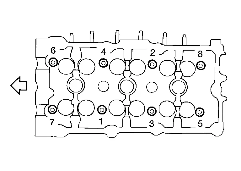

: Engine front -
Bank 2

: Engine front
Remove cylinder heads and gaskets.
CAUTION:
Do not reuse cylinder head gasket (bank 1/bank 2).
INSTALLATION
Turn the crankshaft until No. 1 piston is set at TDC on the compression stroke.
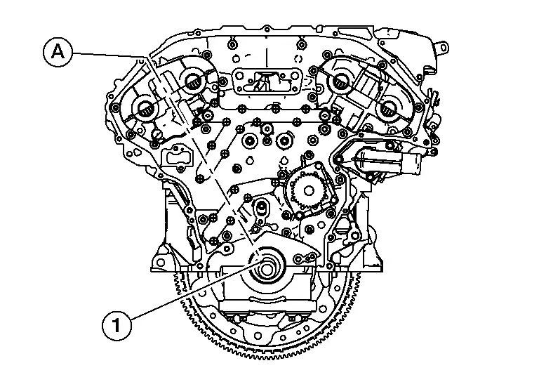
-
The crankshaft key (1) should line up with the bank 1 cylinder center line (A) as shown.
Install new cylinder head gaskets.
CAUTION:
Do not reuse cylinder head gasket (bank 1/bank 2).
Inspect the cylinder head bolts before installing the cylinder heads.
CAUTION:
Cylinder head bolts are tightened by degree rotation tightening method. Whenever the size difference between d1 and d2 exceeds the limit, replace the bolts with new ones.
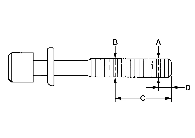
| Limit (d1 - d2) | : 0.11 mm (0.0043 in) |
| (A) | : d1 location |
| (B) | : d2 location |
| (C) | : 48 mm (1.89 in) |
| (D) | : 11 mm (0.43 in) |
-
Lubricate threads and seat surfaces of the bolts with new engine oil.
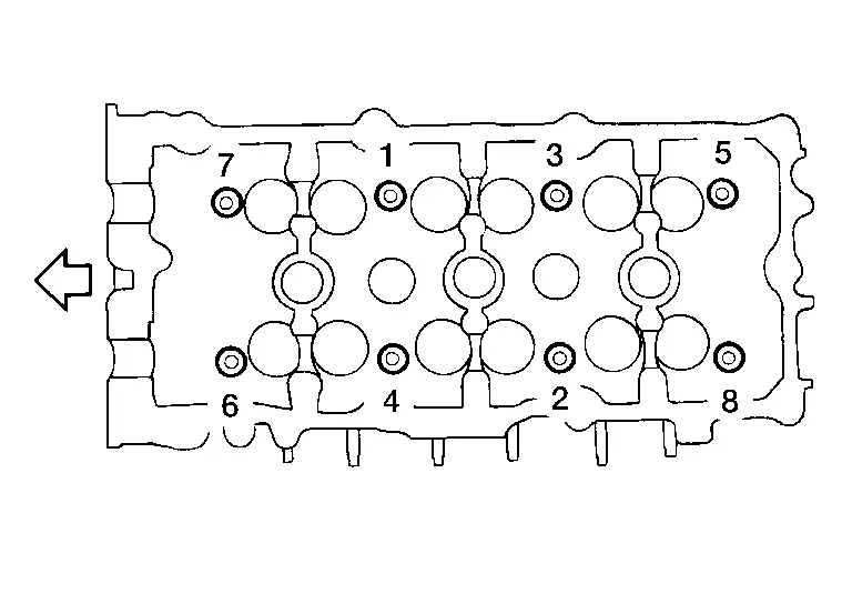
Install the cylinder heads on the cylinder block. Tighten the cylinder head bolts to the specified torque and specified angle in the sequence shown using Tool.
| Tool number | : KV10112100 (BT-8653-A) |
-
Tightening procedure:
| Cylinder head bolts | |
| Step 1 | : Tighten 98.1 N·m (10 kg-m, 72 ft-lb) |
| Step 2 | : Loosen in the reverse order of tightening to 0 N·m (0 kg-m, 0 ft-lb) |
| Step 3 | : Tighten 39.2 N·m (4.0 kg-m, 29 ft-lb) |
| Step 4 | : Tighten 103° - 108° degrees |
| Step 5 | : Tighten 103° - 108° degrees |
-
Bank 1


: Engine front -
Bank 2


: Engine front
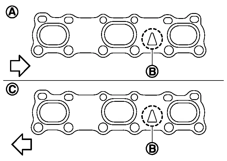
If removed, install the exhaust manifold and three way catalyst (bank 2) using the following procedure:Install the exhaust manifold gasket in the direction shown.

CAUTION:
Do not reuse gasket.
| (A) | : Bank 1 |
| (B) | : Triangle press |
| (C) | : Bank 2 |
 |
: Engine front |
 NOTE:
NOTE:
Number 7 and 8 are tightened a second time.
| Exhaust manifold nut | : 30.9 N·m (3.2 kg-m, 23 ft-lb) |
| (A) | : Bank 2 |
| (B) | : Bank 1 |
 |
: Engine front |
If removed, install the exhaust manifold and three way catalyst (bank 1) using the following procedure:Install the exhaust manifold gasket in the direction shown.
CAUTION:
Do not reuse gasket.
| (A) | : Bank 1 |
| (B) | : Triangle press |
| (C) | : Bank 2 |
 |
: Engine front |

 NOTE:
NOTE:
Number 7 and 8 are tightened a second time.
| Exhaust manifold (bank 1) nuts | : 30.9 N·m (3.2 kg-m, 23 ft-lb) |
| (A) | : Bank 2 |
| (B) | : Bank 1 |
 |
: Engine front |
Install the intake manifold gaskets.
CAUTION:
-
Do not reuse gasket.
-
Install the gaskets with the painted surface facing the intake manifold side.
Installation of the remaining components is in the reverse order of removal.
Disassembly and Assembly
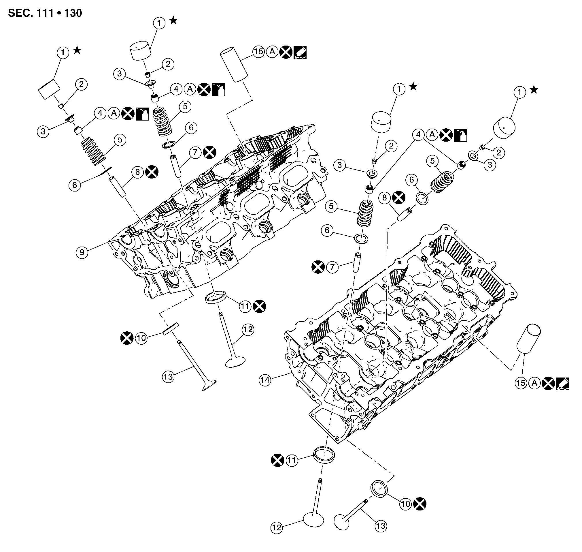
| 1. | Lifter | 2. | Valve collet | 3. | Valve spring retainer |
| 4. | Valve oil seal | 5. | Valve spring | 6. | Valve spring seat |
| 7. | Valve guide (INT) | 8. | Valve guide (EXH) | 9. | Cylinder head (bank 1) |
| 10. | Valve seat (EXH) | 11. | Valve seat (INT) | 12. | Valve (INT) |
| 13. | Valve (EXH) | 14. | Cylinder head (bank 2) | 15. | Spark plug tube |
| A. | Refer to ASSEMBLY |
 : Identify installation position of valve lifters and store without mixing them up.
CAUTION:
-
When installing camshafts, chain tensioners, oil seals, or other sliding parts, lubricate contacting surfaces with new engine oil.
-
Apply new engine oil to threads and seat surface when installing cylinder head, camshaft sprocket, crankshaft pulley, and camshaft bracket.
-
Attach tags to valve lifters so as not to mix them up.
DISASSEMBLY
Remove spark plug. Refer to Exploded View.
Remove valve lifter.
-
Identify installation positions and store them without mixing them up.
Remove valve collet.
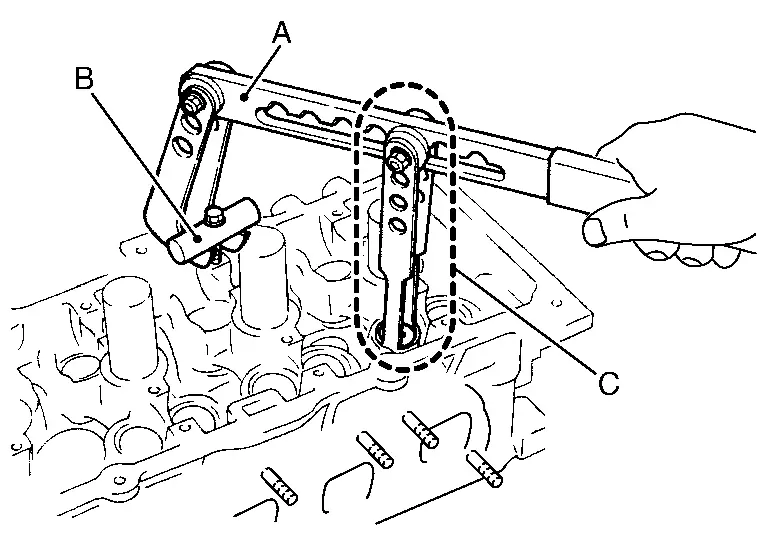
-
Compress the valve spring with suitable tool (A), (B) and (C) and remove the valve collet with a suitable magnetic tool.
CAUTION:
Do not damage valve lifter bore.
Remove valve spring retainer, valve spring and valve spring seat.
Push valve stem to combustion chamber side and remove valve.
-
Identify installation positions, and store them without mixing them up.
Remove valve oil seals using suitable tool (A).
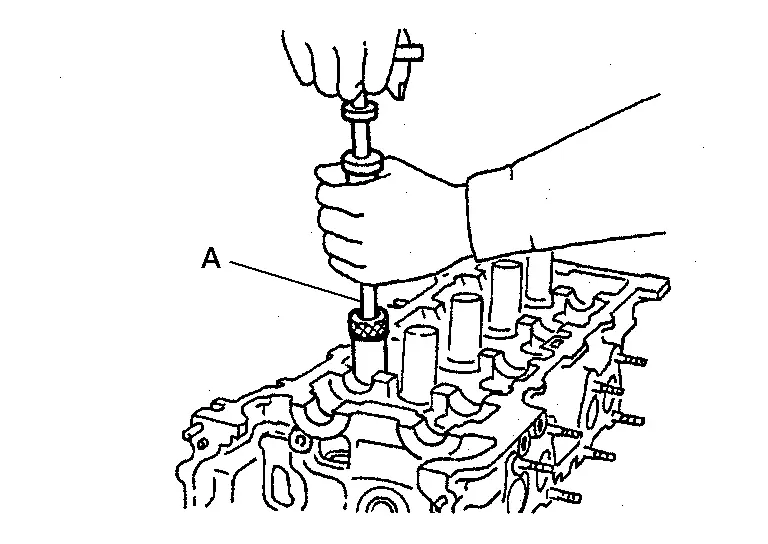
CAUTION:
Do not reuse valve oil seals.
Remove valve seat (if necessary). Refer to Inspection After Disassembly.
Remove valve guide (if necessary). Refer to Inspection After Disassembly.
Remove spark plug tube (if necessary).
-
Using pair of pliers, pull spark plug tube out of cylinder head.
CAUTION:
-
Take care not to damage cylinder head.
-
Once removed, spark plug tube will be deformed and cannot be reused. Do not remove it unless absolutely necessary.
ASSEMBLY
Install valve guide (if removed). Refer to Inspection After Disassembly.
Install valve seat (if removed). Refer to Inspection After Disassembly.
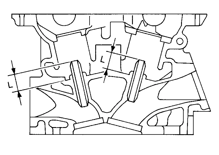
Install valve oil seals using suitable tool (A).
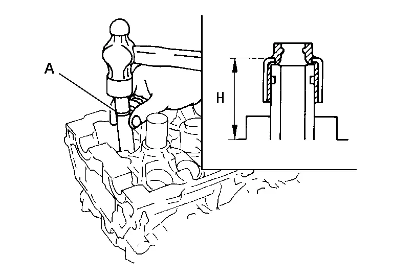
| Height (H) (Without valve spring seat installed) | ||
| Intake and exhaust | : Refer to Cylinder Head. | |
Install valve spring seat.
Install valves.
-
Install it in the original position.
 NOTE:
NOTE:
Larger diameter valves are for intake side.
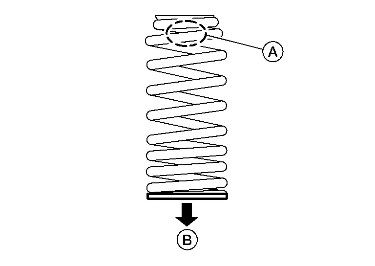
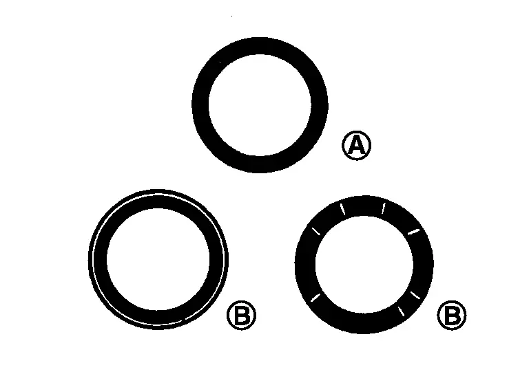
Install valve spring.
-
Install valve spring so that the identification color (A) is facing upward.
-
Install smaller pitch to cylinder head side (B).
-
Intake and exhaust valve springs are the same.
Install valve spring retainer.
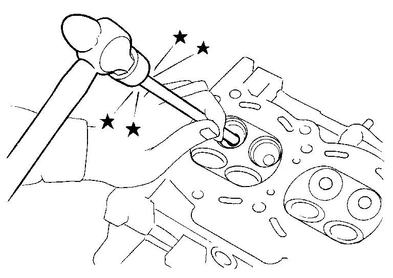
Install valve collet.

-
Compress valve spring using suitable tool (A) attachment (B) and adapter (C). Install valve collet with magnet hand.
CAUTION:
Do not damage valve lifter bore.
-
Tap valve stem edge lightly with plastic hammer after installation to check its installed condition.
Install valve lifter.
-
Install it in the original position.
Install spark plug tube (If removed).
-
Press-fit spark plug tube as follows:
Use Genuine High Strength Locking Sealant or equivalent. Refer to Recommended Chemical Products and Sealants.
Press-fit spark plug tube so that its height (A) is as specified in using suitable tool.
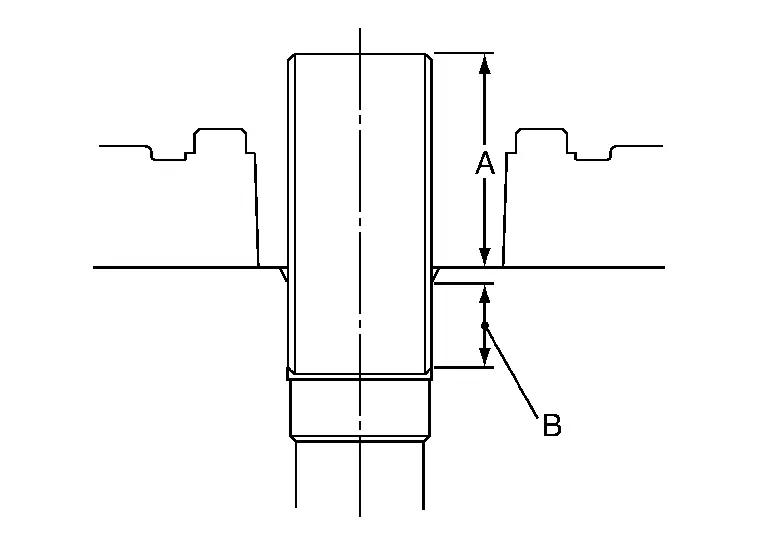
CAUTION:
-
When press-fitting, take care not to deform spark plug tube.
-
After press-fitting, wipe off liquid gasket protruding onto cylinder-head upper face.
| Press-fit height (A) | : 37.7 - 39.1 (1.484 - 1.539 in) |
| (B) | : Locking sealant application area |
Install spark plug. Refer to Exploded View.
Inspection After Disassembly
CYLINDER HEAD DISTORTION
Clean the surface of the cylinder head. Use a reliable straightedge and feeler gauge to check the flatness of cylinder head surface.
Check along six positions as shown.
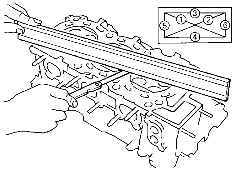
| Head surface distortion | |
| Standard and Limit | : Refer to Cylinder Head. |
If it exceeds the limit, replace the cylinder head.
The limit for cylinder head resurfacing is determined by the cylinder block resurfacing.
| Resurfacing Limit | |
| Amount of cylinder head resurfacing is (A). | |
| Amount of cylinder block resurfacing is (B). | |
| The maximum limit | : A + B = 0.2 mm (0.008 in) |
After resurfacing cylinder head, check that camshaft rotates freely by hand. If resistance is felt, cylinder head must be replaced.
| Nominal cylinder head height | : Refer to Cylinder Head. |
VALVE GUIDE CLEARANCE
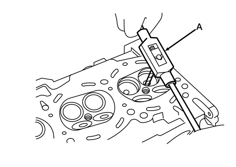
Measure diameter of valve stem using suitable tool (B) as shown.
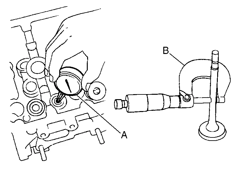
| Standard | : Refer to Cylinder Head. |
Measure the inner diameter of valve guide using suitable tool (A).
| Standard | : Refer to Cylinder Head. |
(Valve guide clearance) = (Valve guide inner diameter) – (Valve stem diameter).
| Standard | : Refer to Cylinder Head. |
If the calculated value exceeds the limit, replace valve and/or valve guide.
VALVE GUIDE REPLACEMENT
When valve guide is removed, replace with oversized [0.2 mm (0.008 in)] valve guide.
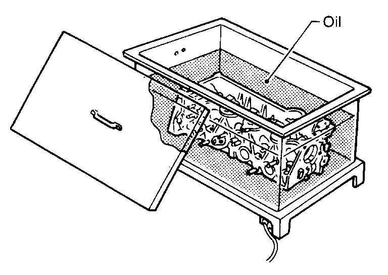
To remove valve guide, heat cylinder head to 110 - 130°C (230 - 266°F) by soaking in heated oil.

WARNING:
Cylinder head contains heat. When working, wear protective equipment to avoid getting burned.
Drive out the valve guide with a press [under a 20 kN (2.2 US ton) pressure] or hammer and suitable tool.
Ream cylinder head valve guide hole using suitable tool (A).

| Standard | : Refer to Cylinder Head. |
Heat cylinder head to 110 - 130°C (230 - 266°F) by soaking in heated oil and press valve guide from camshaft side to the dimensions as shown using suitable tool.
| Standard | : Refer to Cylinder Head. |
WARNING:
Cylinder head contains heat. When working, wear protective equipment to avoid getting burned.
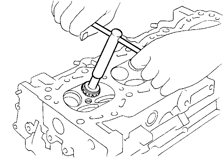
Apply reamer finish to valve guide using suitable tool (A).
| Standard | : Refer to Cylinder Head. |
VALVE SEAT CONTACT
-
After confirming that the dimensions of valve guides and valves are within specifications, perform this procedure.
(A) : OK (B) : NG
-
Apply prussian blue onto contacting surface of valve seat to check the condition of the valve contact on the surface.
-
Check if the contact area band is continuous all around the circumference.
-
If not, grind to adjust valve fitting and check again. If the contacting surface still has NG conditions even after the re-check, replace valve seat.
VALVE SEAT REPLACEMENT
Bore out old seat until it collapses. Boring should not continue beyond the bottom face of the seat recess in cylinder head. Set the machine depth stop to ensure this. Refer to Cylinder Head.
Ream cylinder head (1) recess diameter for service valve seat (2).
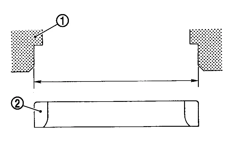
| Standard | Refer to Cylinder Head. |
Be sure to ream in circles concentric to the valve guide center.
This will enable valve seat to fit correctly.
Heat cylinder head to 110 - 130°C (230 - 266°F) by soaking in heated oil.
WARNING:
Cylinder head contains heat. When working, wear protective equipment to avoid getting burned.
Press fit valve seat until it seats on the bottom.
Finish seat to the specified dimensions using suitable tool. Refer to Cylinder Head.
CAUTION:
When using valve seat cutter, firmly grip cutter handle with both hands. Then, press on the contacting surface all around the circumference to cut in a single drive. Improper pressure on with cutter or cutting many different times may result in staged valve seat.
| Seat face angle (α) | Refer to Cylinder Head. |
| Contacting width (W) for intake | |
| Contacting width (W) for exhaust |
VALVE SPRING SQUARENESS
Set a suitable tool (D) along the side of valve spring and rotate spring. Measure the maximum clearance (A) between the top of spring and suitable tool.
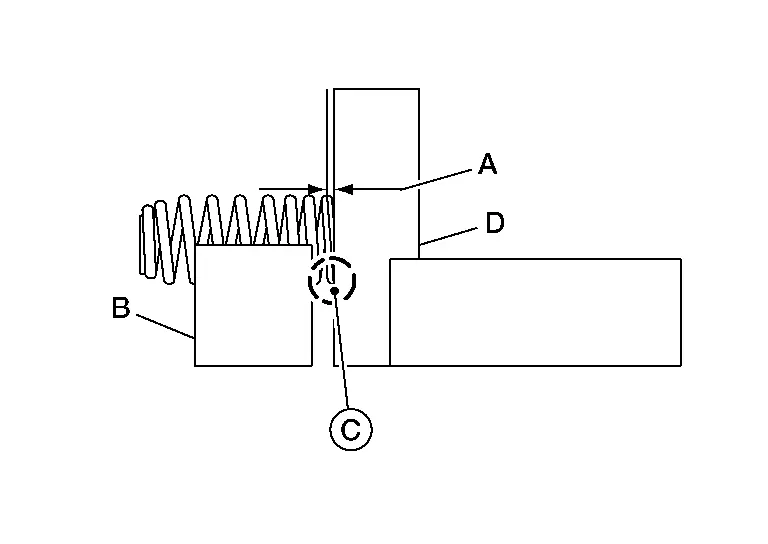
| (B) | : Suitable tool |
| (C) | : Contact area |
| Limit | : Refer to Cylinder Head. |
VALVE SPRING DIMENSIONS AND VALVE SPRING PRESSURE LOAD
Check valve spring pressure at specified spring height.
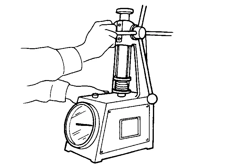
| Standard | : Refer to Cylinder Head. |
| Limit | : Refer to Cylinder Head. |
If it is not within specifications, replace the spring.

Nissan Pathfinder (R53) 2022-2026 Service Manual
Contact Us
Nissan Pathfinder Info Center
Email: info@nipathfinder.com
Phone: +1 (800) 123-4567
Address: 123 Pathfinder Blvd, Nashville, TN 37214, USA
Working Hours: Mon–Fri, 9:00 AM – 5:00 PM (EST)
