Nissan Pathfinder: Removal and Installation - Oil Pan ++
Exploded View
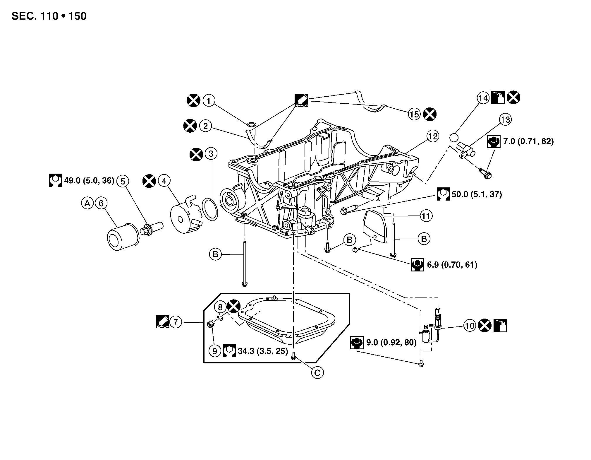
| 1. | O-ring | 2. | Front cover gasket | 3. | Oil cooler gasket |
| 4. | Oil cooler | 5. | Oil cooler connection | 6. | Oil filter |
| 7. | Oil pan (lower) | 8. | Washer | 9. | Drain plug |
| 10. | Engine oil pressure control solenoid valve | 11. | Rear plate cover | 12. | Oil pan (upper) |
| 13. | Crankshaft position sensor (POS) | 14. | O-ring | 15. | Rear oil seal retainer gasket |
| A. | Refer to Removal and Installation. | B. | Refer to Removal and Installation (Upper Oil Pan). | C. | Refer to Removal and Installation (Lower Oil Pan). |
Removal and Installation (Lower Oil Pan)
REMOVAL
WARNING:
You should not remove the oil pan until the exhaust system and cooling system have completely cooled off.
Drain the engine oil. Refer to Draining.
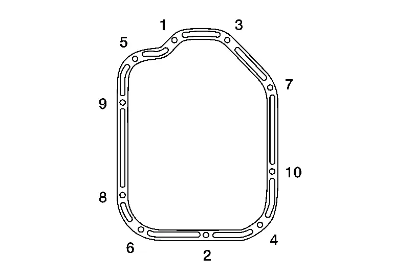
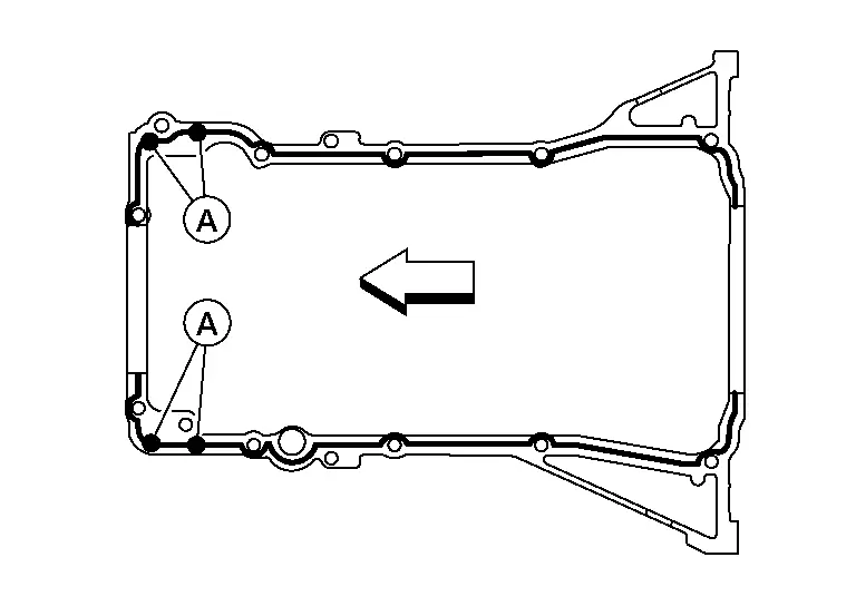
Loosen the oil pan (lower) bolts in reverse of the sequence shown.

Remove the oil pan (lower).
CAUTION:
Do not damage the mating surfaces.
-
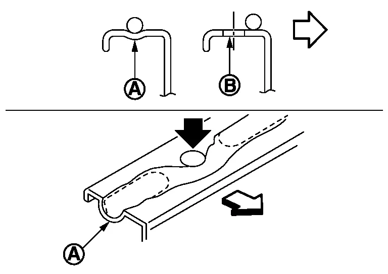
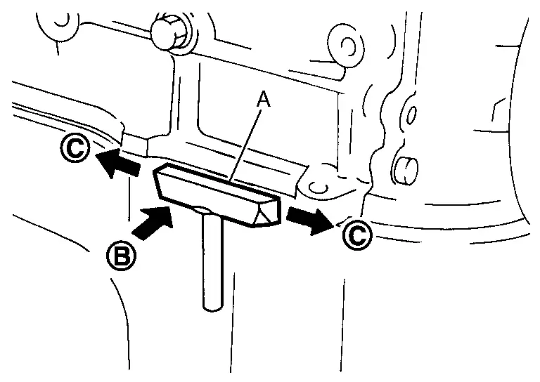
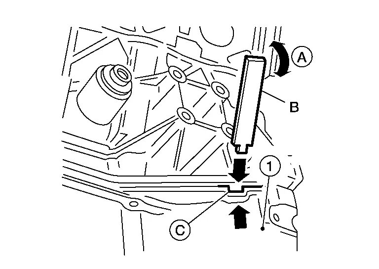
After removing the bolts, separate the mating surface and remove the old liquid gasket using Tool (A).

-
Tap (B) the Tool to insert it.
-
In areas where the Tool is difficult to use, lightly tap to slide (C) it.
Tool number (A) : KV10111100 (NI-37228)
Remove the old sealant from the bolt holes and threads.
INSPECTION AFTER REMOVAL
Clean debris from the oil strainer.
INSTALLATION
Apply a continuous bead of sealant to the oil pan (lower).
-
Be sure the sealant is 4.5 - 5.5 mm (0.177 - 0.217 in) wide.
Use Genuine Silicone RTV Sealant, or equivalent. Refer to Recommended Chemical Products and Sealants.
CAUTION:
-
Installation should be done within 5 minutes after applying liquid gasket.
-
Do not fill the engine with engine oil for at least 30 minutes after the components are installed to allow the sealant to cure.
| (A) | : Groove |
| (B) | : Bolt hole |
 |
: Inside |
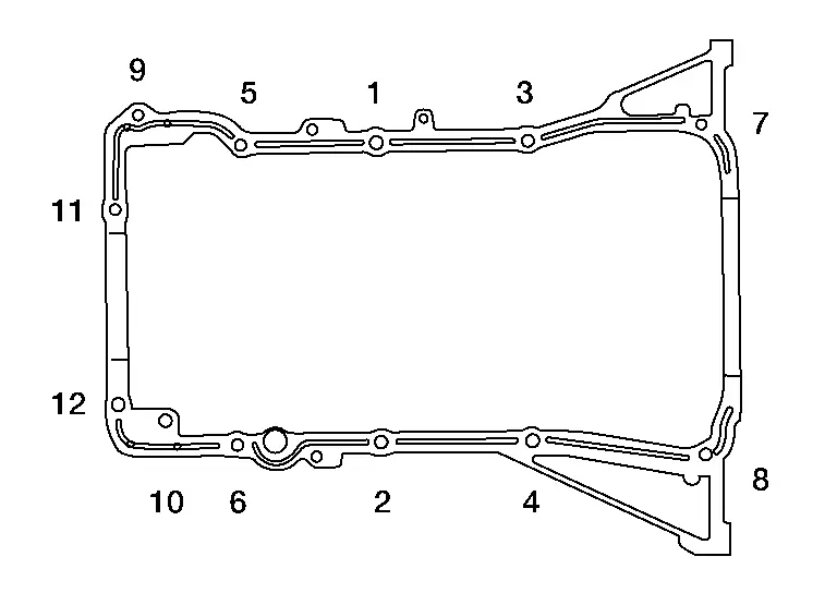
Install the oil pan (lower) and tighten the oil pan (lower) bolts to the specified torque in the sequence shown.
CAUTION:
-
Installation should be done within 5 minutes after applying liquid gasket.
-
Do not fill the engine with engine oil for at least 30 minutes after the components are installed to allow the sealant to cure.
| Oil pan (lower) bolts | : 8.8 N·m (0.90 kg-m, 78 in-lb) |
Refill the engine with engine oil. Refer to Refilling.
INSPECTION AFTER INSTALLATION
Inspect the engine oil level. Refer to Inspection.
Start the engine and check for leaks. Refer to Inspection. Repair as necessary.
Removal and Installation (Upper Oil Pan)
REMOVAL
WARNING:
Do not remove the oil pan until the exhaust system and cooling system have completely cooled off.
CAUTION:
When removing the oil pan (upper) from the engine, first remove the crankshaft position sensor (POS). Do not damage sensor edges or signal plate teeth.
 NOTE:
NOTE:
When removing components such as hoses, tubes/lines, etc., cap or plug openings to prevent fluid from spilling.
Secure the engine assembly to stand. Refer to Removal and Installation.
Remove the oil dipstick.
Remove the drive belt. Refer to Removal and Installation.
Disconnect the harness connectors from compressor.
Remove the compressor. Refer to Exploded View.
Remove the crankshaft pulley as follows:
-
Loosen crankshaft pulley bolt and locate bolt seating surface at 10 mm (0.39 in) from its original position.
-
Position a suitable tool at recess hole of crankshaft pulley to remove crankshaft pulley.
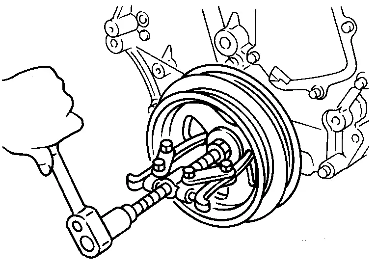
CAUTION:
Do not use a puller claw on the outer diameter of the crankshaft pulley.
Remove water pipe. Refer to Exploded View.
Disconnect the water hoses from the oil cooler.
Remove the oil filter and oil cooler from the oil pan (upper) (if necessary).
Loosen the oil pan (lower) bolts in reverse of the sequence shown.

Remove the oil pan (lower).
CAUTION:
Do not damage the mating surfaces.
-
After removing the bolts, separate the mating surface and remove the old liquid gasket using Tool (A).
-
Tap (B) the Tool to insert it.
-
In areas where the Tool is difficult to use, lightly tap to slide (C) it.
Tool number (A) : KV10111100 (NI-37228)
Remove the old sealant from the bolt holes and threads.
Disconnect the harness connector from the engine oil pressure control solenoid valve.
Remove bolts (B) and remove engine oil pressure control solenoid valve (2).
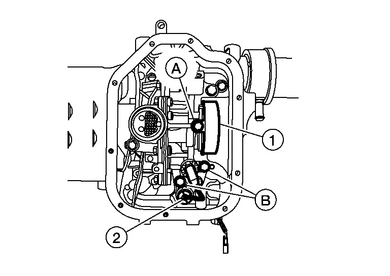
CAUTION:
Do not reuse engine oil pressure control solenoid valve.
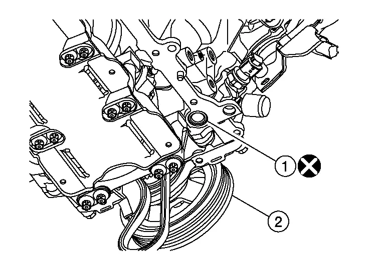
Remove bolt (A) and remove oil pump drive chain cover (1).
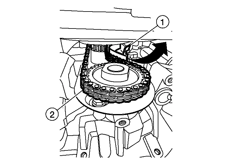
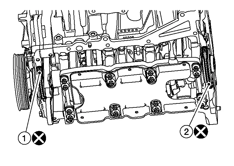
Rotate oil pump drive chain tensioner (1) counterclockwise with a suitable tool and remove oil pump drive chain (2) from oil pump gear.
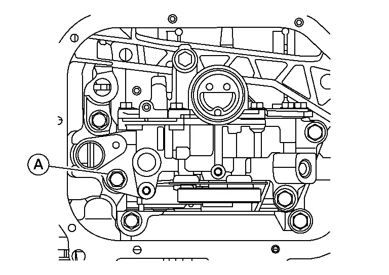
Remove the oil pump bolts (A) in reverse of the sequence shown and remove (if necessary).

CAUTION:
Do not reuse O-rings (1).
 NOTE:
NOTE:
If removal of oil pump is not necessary, remove bolt (A) before removing oil pan (upper).
Remove the oil pan (upper) using the following procedure:
-
Remove the oil pan (upper) bolts in reverse of the sequence shown.

-
Insert a suitable tool (B) into the notch (C) of the oil pan [upper (1)] as shown.
-
Remove the oil pan (upper) by moving the suitable tool up and down (A) as shown.
Remove the O-ring from the bottom of the cylinder block and oil pump housing.
CAUTION:
Do not reuse O-ring.
Remove front cover gasket and rear oil seal retainer gasket.
CAUTION:
Do not reuse front cover gasket or rear oil seal retainer gasket.
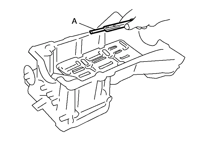
Remove the old sealant from the mating surfaces using a suitable tool (A).
-
Also remove the old sealant from mating surface of the cylinder block.
-
Remove the old sealant from the bolt holes and threads.
CAUTION:
Do not scratch or damage the mating surfaces when cleaning off the old sealant.
INSPECTION AFTER REMOVAL
Clean debris from oil strainer.
INSTALLATION
Apply sealant (A) to the front cover gasket and the rear oil seal retainer gasket as shown.
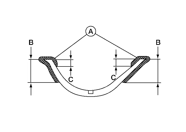
Use Genuine RTV Silicone Sealant or equivalent. Refer to Recommended Chemical Products and Sealants.
CAUTION:
-
Do not reuse front cover gasket or rear oil seal retainer gasket.
-
Installation should be done within 5 minutes after applying liquid gasket.
-
Do not fill the engine with engine oil for at least 30 minutes after the components are installed to allow the sealant to cure.
| Dimension (B) | : 15 mm (0.59 in) |
| Dimension (C) | : 5 mm (0.20 in) |
Install the front cover gasket (1) and rear oil seal retainer gasket (2) as shown.
CAUTION:
Do not reuse front cover gasket or rear oil seal retainer gasket.
 |
: Engine front |
Apply a bead of sealant to the cylinder block mating surface of the oil pan (upper) as shown.
-
Be sure the sealant is applied 4.0 - 5.0 mm (0.157 - 0.197 in) as shown. Increase the bead to 4.5 - 5.5 mm (0.177 - 0.217 in) at the locations (A) indicated.
Use Genuine RTV Silicone Sealant, or equivalent. Refer to Recommended Chemical Products and Sealants.
CAUTION:
-
Installation should be done within 5 minutes after applying liquid gasket.
-
Do not fill the engine with engine oil for at least 30 minutes after the components are installed to allow the sealant to cure.

: Engine front -
Install new O-ring (1) into the cylinder block before installing oil pan (upper).
CAUTION:
Do not reuse O-ring.
| (2) | : Crankshaft pulley |
Install the oil pan (upper).
-
Tighten bolts (1) and (2) to specification within five minutes of applying the liquid gasket.
-
Tighten the remaining oil pan (upper) bolts to specification in the sequence shown.
CAUTION:
-
Installation should be done within 5 minutes after applying liquid gasket.
-
Do not fill the engine with engine oil for at least 30 minutes after the components are installed to allow the sealant to cure.
| Oil pan (upper) bolts | : 22.0 N·m (2.2 kg-m, 16 ft-lb) |
Install the oil pump and new O-rings (1) and tighten oil pump bolts (A) to the specified torque in the sequence shown.
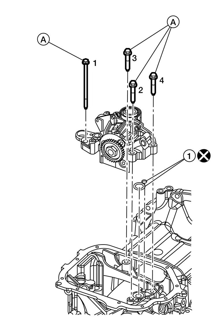
CAUTION:
Do not reuse O-rings.
| Oil pump bolts | : 22.0 N·m (2.2 kg-m, 16 ft-lb) |
Apply a continuous bead of sealant to the oil pan (lower).

-
Be sure the sealant is 4.5 - 5.5 mm (0.177 - 0.217 in) wide.
Use Genuine Silicone RTV Sealant, or equivalent. Refer to Recommended Chemical Products and Sealants.
CAUTION:
-
Installation should be done within 5 minutes after applying liquid gasket.
-
Do not fill the engine with engine oil for at least 30 minutes after the components are installed to allow the sealant to cure.
| (A) | : Groove |
| (B) | : Bolt hole |
 |
: Inside |
Install the oil pan (lower) and tighten the oil pan (lower) bolts to the specified torque in the sequence shown.

CAUTION:
-
Installation should be done within 5 minutes after applying liquid gasket.
-
Do not fill the engine with engine oil for at least 30 minutes after the components are installed to allow the sealant to cure.
| Oil pan (lower) bolts | : 8.8 N·m (0.90 kg-m, 78 in-lb) |
Installation of the remaining components is in the reverse order of removal.
INSPECTION AFTER INSTALLATION
-
Before starting engine, check oil/fluid levels including engine coolant and engine oil. If there is less than required quantity, fill to the specified level. Refer to Fluids and Lubricants (FOR USA AND CANADA) or Fluids and Lubricants (FOR MEXICO).
-
Use procedure below to check for fuel leaks.
-
Place ignition switch in the "ON" position (with engine stopped). With fuel pressure applied to fuel piping, check for fuel leaks at connection points.
-
Start engine. With engine speed increased, check again for fuel leaks at connection points.
-
Run engine to check for unusual noise and vibration.
 NOTE:
NOTE:
If hydraulic pressure inside timing chain tensioner drops after removal and installation, slack in the guide may generate a pounding noise during and just after engine start. However, this is normal. Noise will stop after hydraulic pressure rises.
-
Warm up engine thoroughly to make sure there are no leaks of fuel, exhaust gas, or any oils/fluids including engine oil and engine coolant.
-
Bleed air from passages in lines and hoses, such as in cooling system.
-
After cooling down engine, again check oil/fluid levels including engine oil and engine coolant. Refill to specified level, if necessary.
-
Summary of the inspection items:
Item Before starting engine Engine running After engine stopped Engine coolant Level Leakage Level Engine oil Level Leakage Level Transmission/transaxle fluid A/T and CVT Models Leakage Level/Leakage Leakage M/T Models Level/Leakage Leakage Level/Leakage Other oils and fluids* Level Leakage Level Fuel Leakage Leakage Leakage Exhaust gas — Leakage — *Power steering fluid, brake fluid, etc.

Nissan Pathfinder (R53) 2022-2026 Service Manual
Contact Us
Nissan Pathfinder Info Center
Email: info@nipathfinder.com
Phone: +1 (800) 123-4567
Address: 123 Pathfinder Blvd, Nashville, TN 37214, USA
Working Hours: Mon–Fri, 9:00 AM – 5:00 PM (EST)
