Nissan Pathfinder: Removal and Installation - Fuel Injector and Fuel Tube ++
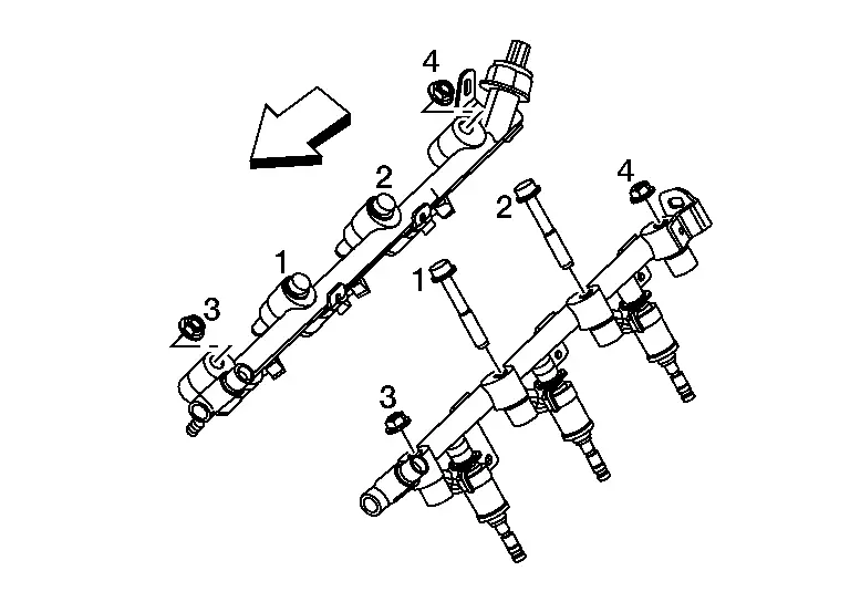
Exploded View
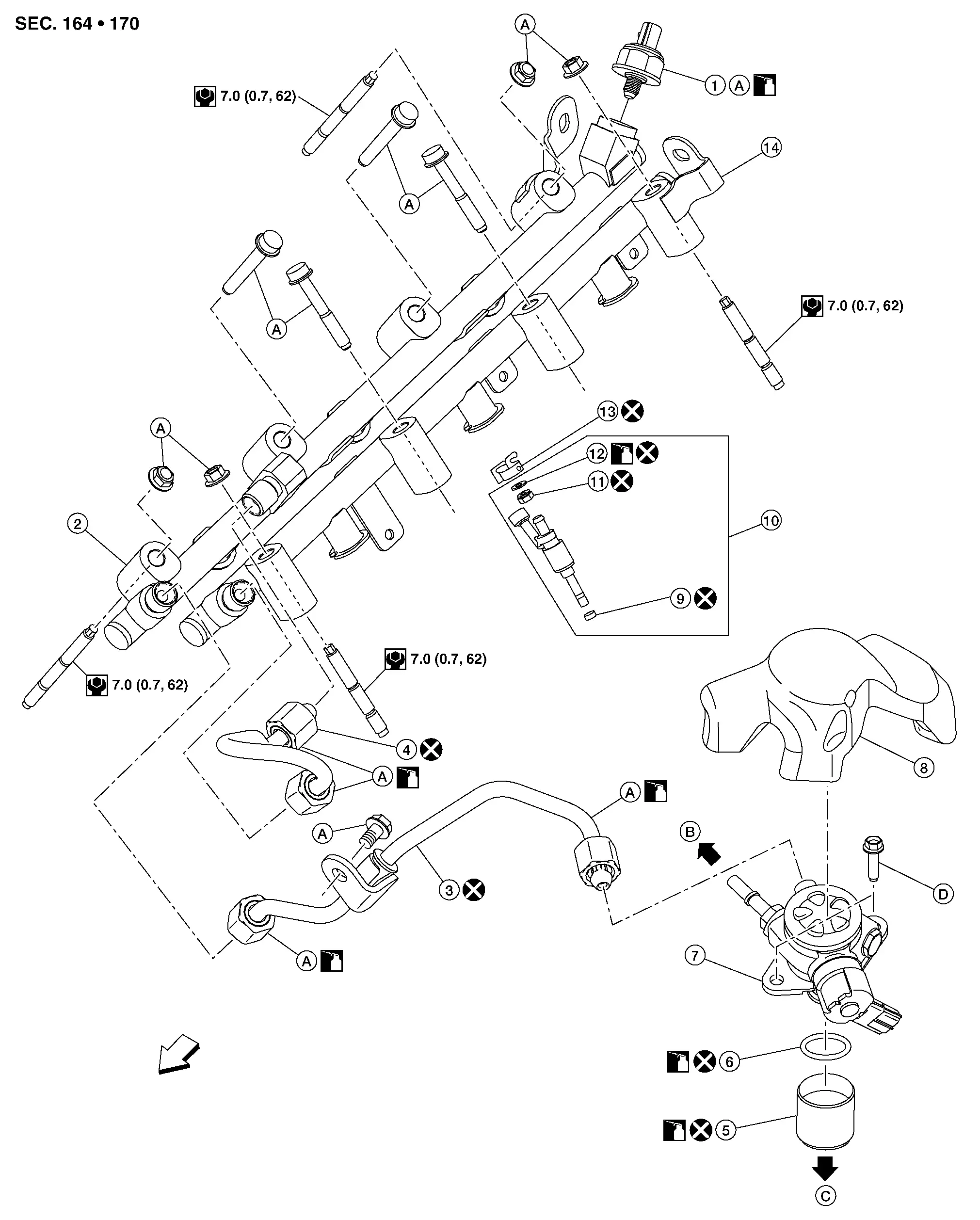
| 1. | Fuel rail pressure sensor | 2. | Fuel rail (bank 1) | 3. | High pressure fuel tube (pump side) |
| 4. | High pressure fuel tube (bank side) | 5. | Lifter | 6. | O-ring |
| 7. | High pressure fuel pump | 8. | High pressure fuel pump insulator | 9. | Seal ring |
| 10. | Injector | 11. | Backup ring | 12. | O-ring (green) |
| 13. | Injector holder | 14. | Fuel rail (bank 2) | A. | Refer to Removal and Installation. |
| B. | To fuel feed hose | C. | To camshaft bracket no. 1. Refer to Exploded View. | D. | Refer to Removal and Installation |
 |
Engine front |
Removal and Installation
REMOVAL
WARNING:
-
Be sure to read Precaution for Handling High Pressure Fuel System when working on the high pressure fuel system.
-
Put a “CAUTION: FLAMMABLE” sign in the workshop.
-
Be sure to work in a well ventilated area and furnish workshop with a CO2 fire extinguisher.
-
Do not smoke while servicing fuel system. Keep open flames and sparks away from the work area.
CAUTION:
-
Do not remove or disassemble parts unless instructed as shown.
-
Be sure to follow the tightening instruction to avoid fuel leaks.
 NOTE:
NOTE:
When removing components such as hoses, tubes/lines, etc., cap or plug openings to prevent fluid from spilling.
Release fuel pressure. Refer to Work Procedure.
Remove intake manifold. Refer to Removal and Installation.
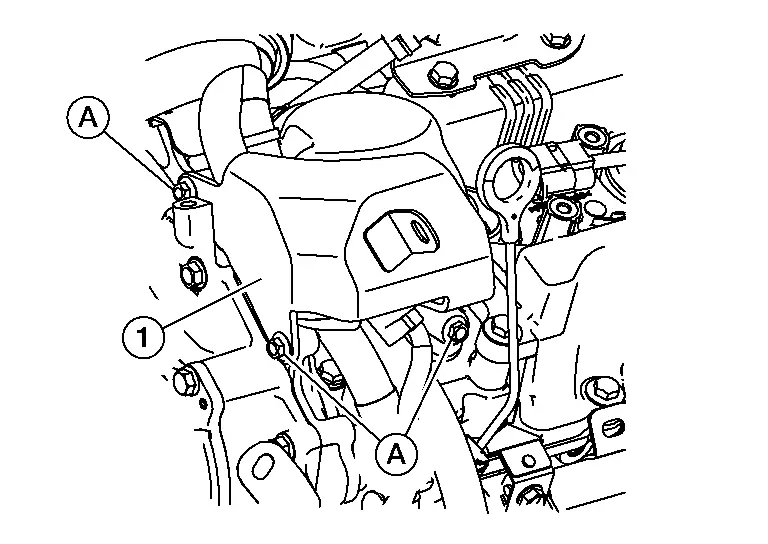
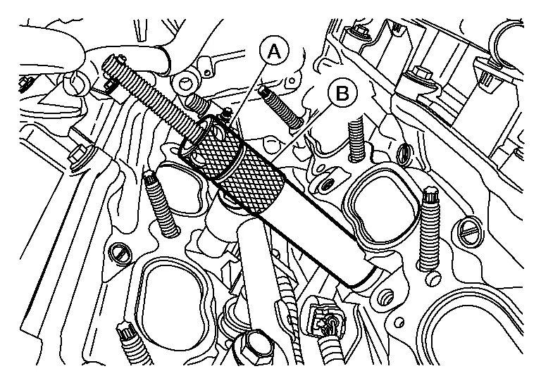
Remove bolts (A) and remove high pressure fuel pump cover (1).
Remove high pressure fuel pump insulator.
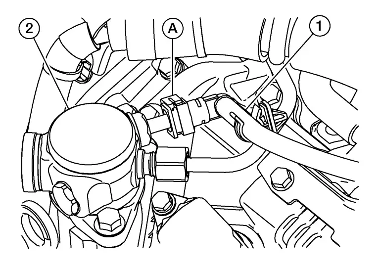
Release clip (A) and disconnect fuel feed hose (1) from high pressure fuel pump (2).
Release fuel feed hose from clip and reposition.
Remove insulator. Refer to Exploded View.
Remove high pressure fuel tube (pump side) and high pressure fuel tube (bank side).
CAUTION:
Do not reuse high pressure fuel tube (pump side) and high pressure fuel tube (bank side).
Disconnect harness connectors from fuel injectors and remove fuel injector harness.
Disconnect the harness connector from the fuel rail pressure sensor.
Remove fuel rail pressure sensor from fuel rail (bank 1) (if necessary).
CAUTION:
Do not reuse fuel rail pressure sensor (if removed).
Remove fuel rail (bank 1) or fuel rail (bank 2) nuts and bolts in reverse of the sequence shown.

CAUTION:
-
Be careful with remaining fuel that may come out from fuel rail (bank 1) or fuel rail (bank 2).
-
Be careful not to damage injector nozzles during removal.
-
Do not bump or drop fuel injector.
-
Do not disassemble fuel injector.
 |
: Engine front |
Remove fuel injector holders from fuel rail (bank 1) or fuel rail (bank 2).
CAUTION:
Do not reuse fuel injector holders.
Remove fuel rail (bank 1) or fuel rail (bank 2).
CAUTION:
Do not reuse fuel rail (bank 1) if fuel rail pressure sensor is removed.
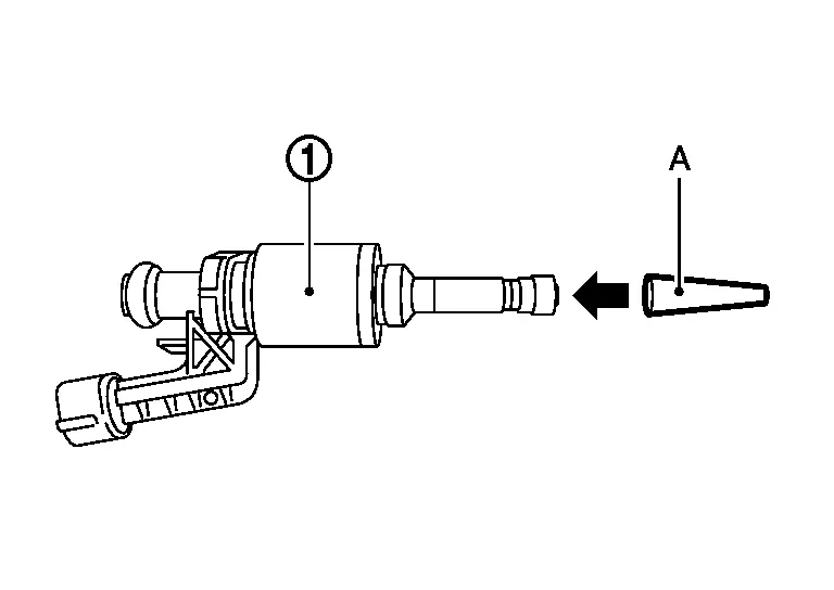
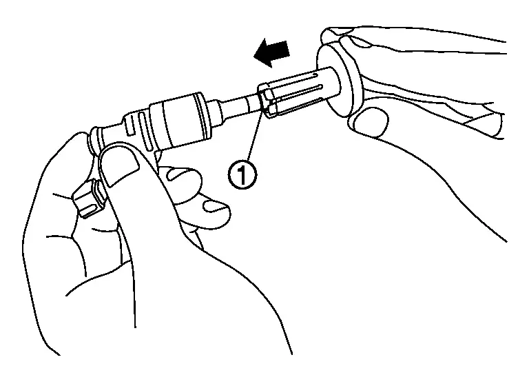
Remove fuel injectors from cylinder head using the following procedure:Install Tool onto fuel injector.
-
Make sure Tool is installed so it pulls from shaded region (A) of fuel injector.
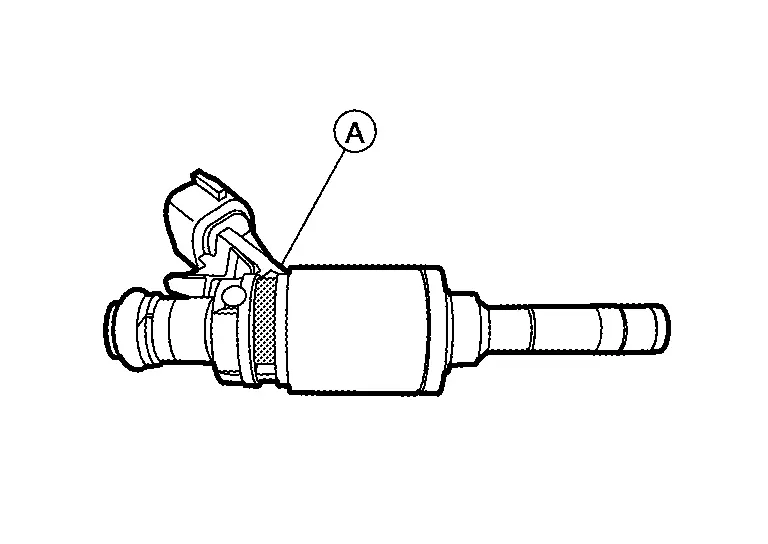
| Tool number | : — (NI-50366) |
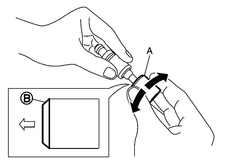
 NOTE:
NOTE:
Do not allow body (B) of Tool to rotate when removing fuel injector.
Remove fuel injector and Tool.CAUTION:
Do not reuse fuel injector holder, O-ring (green) and back-up ring.
| Tool number | : — (NI-50366) |
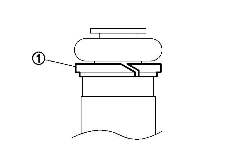
Cut seal ring (1) while pinching it. Be careful not to damage injector.
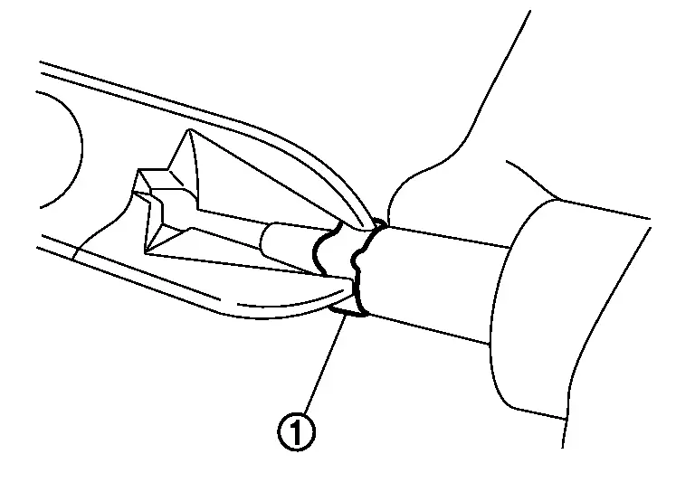
CAUTION:
Do not reuse seal ring.
INSTALLATION
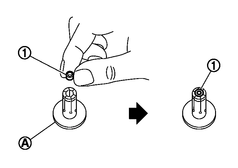
Install seal ring to fuel injector using the following procedure:
CAUTION:
-
Handle seal ring with bare hands. Do not wear gloves.
-
Do not apply engine oil to seal ring.
-
Do not clean seal ring with solvent.
-
Do not reuse seal ring
| Tool number (A) | : KV10119720 (NI-50364) |
CAUTION:
Do not reuse seal ring.
| Tool number (A) | : KV10119730 (NI-50364) |
CAUTION:
-
Be careful that seal ring does not exceed the groove portion of fuel injector.
-
Be sure to keep Tool straight while installing seal ring or seal ring may be damaged.
| Tool number (A) | : KV10119710 (NI-50364) |
CAUTION:
Be careful of installation direction of Tool. The chamfer (B) on the Tool should be installed towards the injector.
 NOTE:
NOTE:
This operation is for compressing the seal ring to eliminate stretching of seal ring caused by installation and for preventing sticking when inserting injector into cylinder head.
 |
: Injector side |
Install O-ring and backup ring to fuel injector.
CAUTION:
-
Do not reuse O-ring and backup ring.
-
Handle O-ring with bare hands. Do not wear gloves.
-
Lubricate O-ring with new non-silicone engine oil.
-
Do not allow engine oil to enter fuel passage ways.
-
Do not clean O-ring with solvent.
-
Check that O-ring and its mating part are free of foreign material.
-
When installing O-ring, be careful not to scratch it with tool or fingernails. Also be careful not to twist or stretch O-ring. If O-ring was stretched while it was being attached, do not insert it immediately into fuel tube.
-
Insert new O-ring straight into fuel rail. Do not decenter or twist it.
-
Always install the back up ring (1) in the right direction as shown.
Install fuel injector (5) to fuel rail (1) using the following procedure:
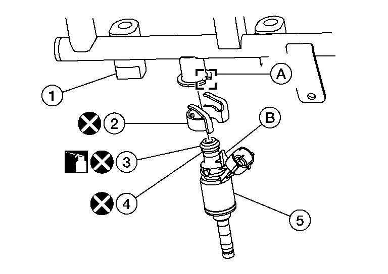
CAUTION:
-
Do not reuse injector holder.
-
Be careful to keep fuel injector holder from interfering with O-ring. If interference occurs, replace O-ring.
-
Insert it while matching it to the axial center.
-
Insert so that protrusion (B) of fuel injector is aligned to cutout (A).
-
Check that protrusions of fuel injectors and fuel rail are aligned with cutouts of clips after installation.
| (3) | : O-ring (green) |
| (4) | : Backup ring |
Install fuel rail and fuel injector assembly to cylinder head.
-
Tighten bolts and nuts in two steps in the sequence shown.
Step 1 : 10.0 N·m (1.0 kg-m, 89 in-lb) Step 2 : 22.0 N·m (2.2 kg-m, 16 ft-lb) 
: Engine front
Install fuel rail pressure sensor using the following procedure (if necessary):
CAUTION:
-
Do not use a fuel pressure sensor that has been dropped.
-
Do not reuse fuel rail pressure sensor or fuel rail (bank 1) if fuel rail pressure sensor is removed.
CAUTION:
Check that fuel rail and fuel pressure sensor threads have no damage, foreign matter, or stains.
Hand tighten fuel rail pressure sensor. Tighten fuel pressure sensor to the specified torque.| Fuel rail pressure sensor | : 10 N·m (1.0 kg-m, 89 in-lb) |
CAUTION:
Do not exceed 60 N·m (6.1 kg-m, 44 ft-lb) during final torquing of fuel rail pressure.
| Angle | : 35° ± 5° |
| Tool number | : KV10112100 (BT-8653-A) |
Install high pressure fuel tube (pump side) and high pressure fuel tube (bank side) using the following procedure:
CAUTION:
-
Do not reuse high pressure fuel tube (pump side) or high pressure fuel tube (bank side).
-
Do not apply engine oil to threads of high pressure fuel pump, fuel rail (bank 1), fuel rail (bank 2), high pressure fuel tube (pump side) or high pressure fuel tube (bank side).
-
Do not use high pressure fuel tube (pump side) or high pressure fuel tube (bank side) if its terminal tip is damaged.
-
Check that there is no foreign material on the high pressure fuel tube (pump side) or high pressure fuel tube (bank side) flare nipple or flare nuts.
-
If scratches or damage are visible on flare nipple of high pressure fuel tube, do not use it.
-
If flare nut is difficult to tighten, inspect threads for damage and replace if damage is present.
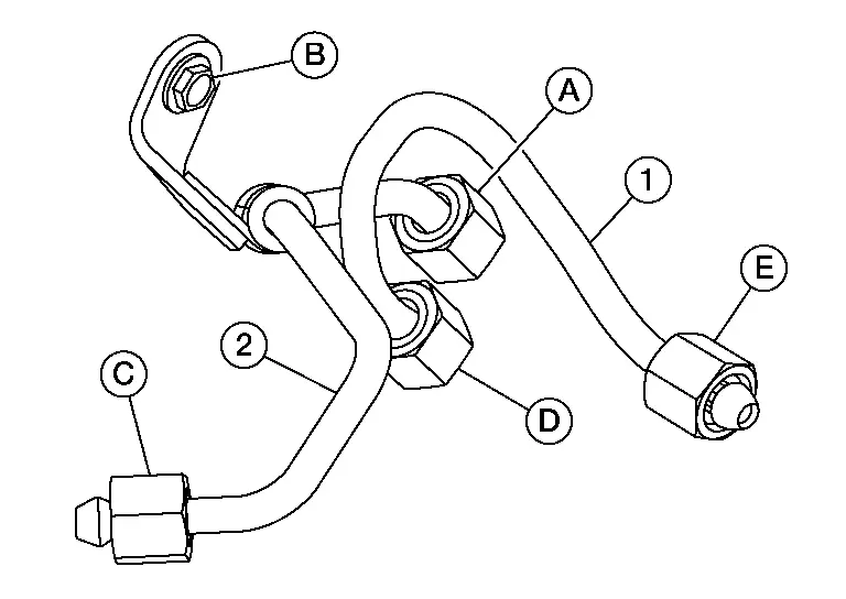
CAUTION:
When hand tightening the flare nuts, insert them so that they are aligned with the center of the pipe.
 NOTE:
NOTE:
Should be no gap between high pressure fuel tube, high pressure fuel tube bracket and rear timing chain case.
Hand tighten bolt (B). Tighten flare nut (C) and then flare nut (A) to the specified torque.| Flare nut | : 15 N·m (1.5 kg-m, 11 ft-lb) |
| Flare nut | : 23.0 N·m (2.3 kg-m, 17 ft-lb) |
| Bolt | : 13.5 N·m (1.4 kg-m, 10 ft-lb) |
CAUTION:
When hand tightening the flare nuts, insert them so that they are aligned with the center of the pipe.
Tighten flare nut (E) and then flare nut (D) to the specified torque.| Flare nut | : 15 N·m (1.5 kg-m, 11 ft-lb) |
| Flare nut | : 23.0 N·m (2.3 kg-m, 17 ft-lb) |
Installation of the remaining components is in the reverse order of removal.
CAUTION:
After checking for fuel leaks, maintain ten minutes of idling to bleed the fuel line.
-
If fuel injectors are replaced, perform "IDLE AIR VOLUME LEARNING". Refer to Description.
-
Check for fuel leaks. Refer to Inspection.
-
Tighten high pressure fuel pump cover bolts to the specified torque in the sequence shown.
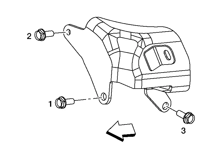
High pressure fuel pump cover bolts : 11.0 N·m (1.1 kg-m, 8 ft-lb) 
: Engine front
Inspection
Check for Fuel Leaks
-
Place ignition switch in the “ON” position (with the engine stopped). With fuel pressure applied to fuel piping, check that there is no fuel leaks at connection points.
 NOTE:
NOTE:
Use mirrors for checking at points out of clear sight.
-
Start the engine. With engine speed increased, check again that there is no fuel leaks at connection points.
CAUTION:
Do not touch the engine immediately after it is stopped because the engine is extremely hot.

Nissan Pathfinder (R53) 2022-2026 Service Manual
Contact Us
Nissan Pathfinder Info Center
Email: info@nipathfinder.com
Phone: +1 (800) 123-4567
Address: 123 Pathfinder Blvd, Nashville, TN 37214, USA
Working Hours: Mon–Fri, 9:00 AM – 5:00 PM (EST)
