Nissan Pathfinder: Removal and Installation - Rear Timing Chain Case ++
Exploded View
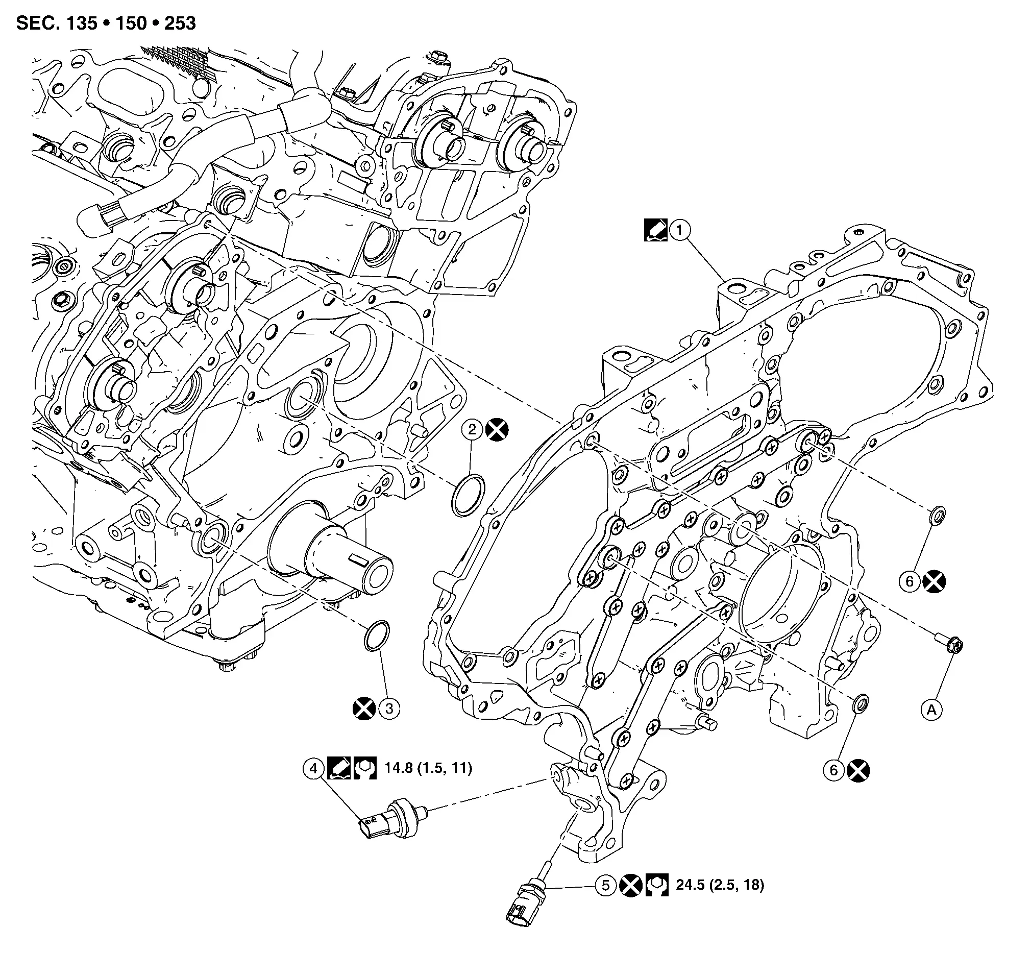
| 1. | Rear timing chain case | 2. | O-ring | 3. | O-ring |
| 4. | Engine oil pressure sensor | 5. | Engine oil temperature sensor | 6. | O-ring |
| A. | Refer to Removal and Installation. |
Removal and Installation
CAUTION:
After removing timing chain, do not turn the crankshaft and camshaft separately, or the valves will strike the pistons.
REMOVAL
Remove the timing chain (primary), camshaft sprockets and timing chain (secondary). Refer to Removal and Installation.
Disconnect the harness connector from the engine oil temperature sensor and engine oil pressure sensor.
Remove the rear timing chain case.
CAUTION:
-
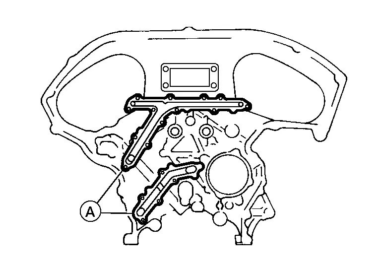
Do not remove the plate metal cover (A) for the oil passage.
-
After removing the chain case, do not apply any load to the case that might bend it.
CAUTION:
Do not damage the mating surfaces.
-
After removing the bolts, separate the mating surface and remove the old liquid gasket using Tool (A).
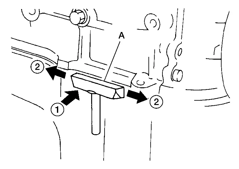
Tool number : KV10111100 (NI-37228) -
Tap the Tool to insert it (1).
-
In areas where the Tool is difficult to use, lightly tap to slide it (2).
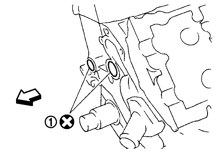
Remove O-rings (1) from cylinder block.

CAUTION:
Do not reuse O-rings.
 |
: Engine front |
Use a suitable tool to remove all of the old liquid gasket from the front and rear timing chain case and opposite mating surfaces.
CAUTION:
Do not damage the mating surfaces.
Remove all old liquid gasket (A) from all the bolt holes (B) and bolts.
CAUTION:
Do not damage the threads or mating surfaces.
Remove the following parts from the rear timing chain case (if necessary):
-
Remove the water pump. Refer to Exploded View.
CAUTION:
Do not reuse O-rings.
-
Remove the engine oil temperature sensor.
CAUTION:
Do not reuse engine oil temperature sensor (if removed).
-
Remove the engine oil pressure sensor.
-
Remove old liquid gasket from engine oil pressure sensor and rear timing chain case port.
-
INSTALLATION
Install O-rings (1) on cylinder block.
 |
: Engine front |
CAUTION:
Do not reuse O-rings.
Apply a continuous bead of liquid gasket (G) to the rear timing chain case (1) as shown.
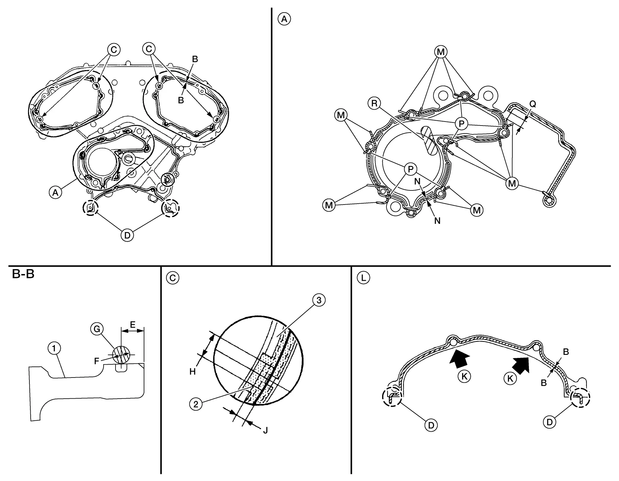
| A. | View A | D. | Protrusion of liquid gasket | E. | 4 mm (0.16 in) |
| F. | 2.6 - 3.6 mm (0.102 - 0.142 in) | H. | 5 mm (0.20 in) | J. | 2 mm (0.08 in) |
| L. | View L | M. | Protrusion of liquid gasket | N. | 2.6 - 2.8 mm (0.102 - 0.110 in) liquid gasket bead diameter |
| P. | Gap of 1 mm (0.04 in) between beads of liquid gasket | Q. | Gap of 8 mm (0.31 in) |
CAUTION:
-
Installation should be done within 5 minutes after applying liquid gasket.
-
Do not fill the engine with engine oil for at least 30 minutes after the components are installed to allow the sealant to cure.
-
Wipe off liquid gasket where it touches the engine coolant passage at point “R”.
-
Apply liquid gasket to rear timing chain case at camshaft bracket No. 1 (3) and cylinder head (2) mating surface as shown(C).
-
Apply liquid gasket to outside of bolt holes at location (K).
-
Follow the installation instructions for applying the liquid gasket. Pay particular attention to the water pump and cylinder area.
Apply Genuine Silicone RTV Sealant or equivalent. Refer to Recommended Chemical Products and Sealants.
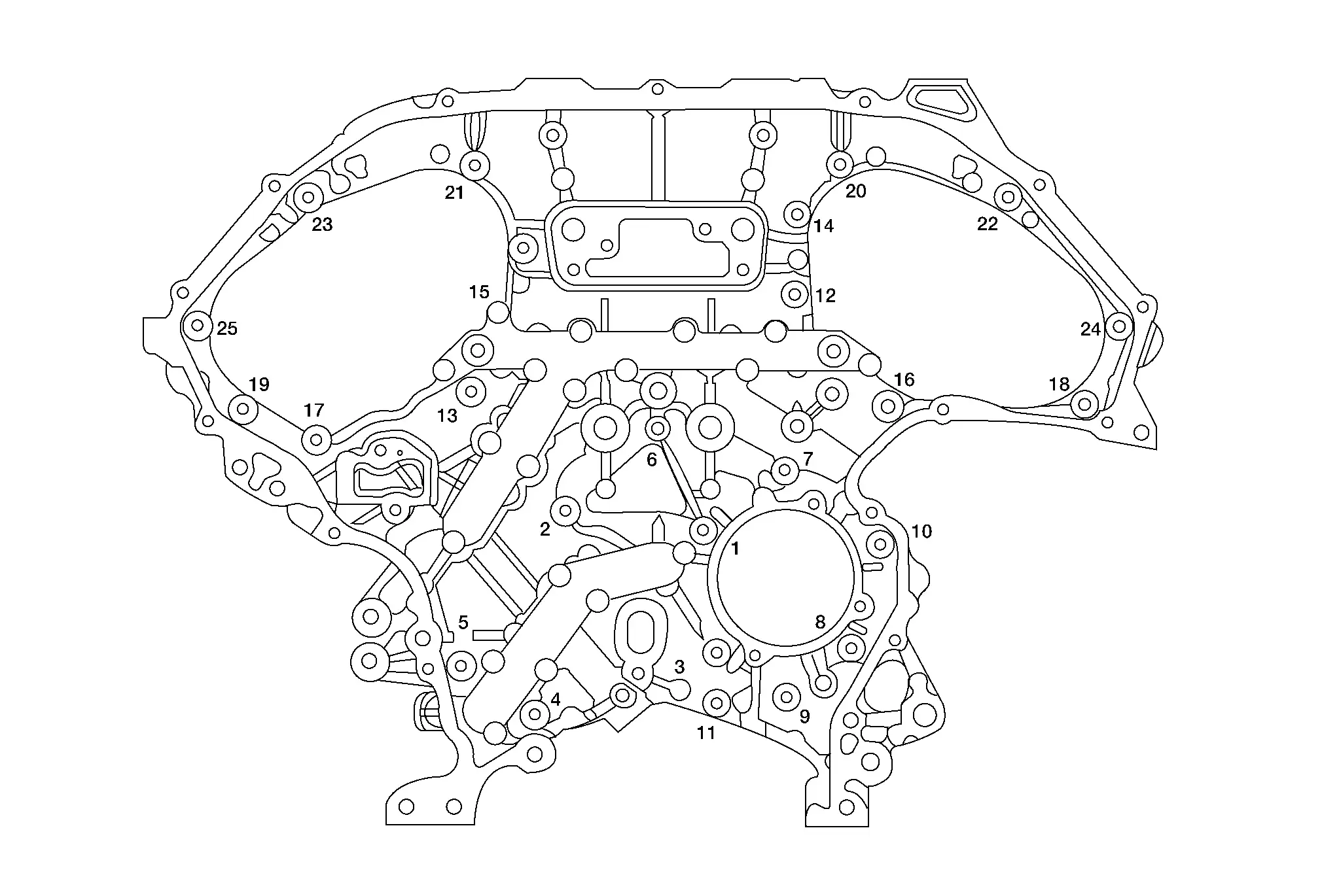
Align the rear timing chain case and water pump assembly with the dowel pins (RH and LH) on the cylinder block and install the case. Make sure the O-rings stay in place during installation.Install and tighten the bolts to the specified torque on the sequence shown.

 NOTE:
NOTE:
There are two bolt lengths used. Follow the chart below for proper bolt length specifications.
| Bolt length | Bolt position | Torque specification |
| 20 mm (0.79 in) | 1, 2, 3, 6, 7, 8, 9, 10 | 12.7 N·m (1.3 kg-m, 9 ft-lb) |
| 16 mm (0.63 in) | All except the above | 12.7 N·m (1.3 kg-m, 9 ft-lb) |
 NOTE:
NOTE:
If liquid gasket protrudes, wipe it off immediately.
Apply liquid gasket and install the engine oil pressure sensor (if removed).
-
Apply Genuine Silicone RTV Sealant or equivalent. Refer to Recommended Chemical Products and Sealants.
Install the engine oil temperature sensor (if removed).
CAUTION:
Do not reuse engine oil temperature sensor (if removed).
Install new O-rings to water pump (1).
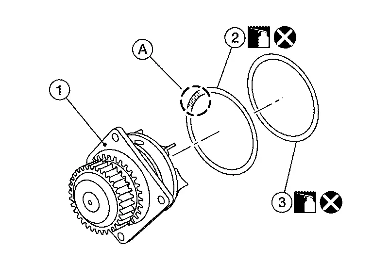
-
Apply engine coolant to O-rings (2,3).
-
Locate O-ring (2) with white paint mark (A) to engine front side.
CAUTION:
Do not reuse O-rings.
Install the water pump. Refer to Exploded View.
Installation of the remaining components is in the reverse order of removal.
INSPECTION AFTER INSTALLATION
-
Before starting engine, check oil/fluid levels including engine coolant and engine oil. If there is less than required quantity, fill to the specified level. Refer to Fluids and Lubricants (FOR USA AND CANADA) or Fluids and Lubricants (FOR MEXICO).
-
Use procedure below to check for fuel leaks.
-
Place ignition switch in the "ON" position (with engine stopped). With fuel pressure applied to fuel piping, check for fuel leaks at connection points.
-
Start engine. With engine speed increased, check again for fuel leaks at connection points.
-
Run engine to check for unusual noise and vibration.
 NOTE:
NOTE:
If hydraulic pressure inside timing chain tensioner drops after removal and installation, slack in the guide may generate a pounding noise during and just after engine start. However, this is normal. Noise will stop after hydraulic pressure rises.
-
Warm up engine thoroughly to make sure there are no leaks of fuel, exhaust gas, or any oils/fluids including engine oil and engine coolant.
-
Bleed air from passages in lines and hoses, such as in cooling system.
-
After cooling down engine, again check oil/fluid levels including engine oil and engine coolant. Refill to specified level, if necessary.
-
Summary of the inspection items:
Item Before starting engine Engine running After engine stopped Engine coolant Level Leakage Level Engine oil Level Leakage Level Transmission/transaxle fluid A/T and CVT Models Leakage Level/Leakage Leakage M/T Models Level/Leakage Leakage Level/Leakage Other oils and fluids* Level Leakage Level Fuel Leakage Leakage Leakage Exhaust gas — Leakage — *Power steering fluid, brake fluid, etc.

Nissan Pathfinder (R53) 2022-2026 Service Manual
Contact Us
Nissan Pathfinder Info Center
Email: info@nipathfinder.com
Phone: +1 (800) 123-4567
Address: 123 Pathfinder Blvd, Nashville, TN 37214, USA
Working Hours: Mon–Fri, 9:00 AM – 5:00 PM (EST)
