Nissan Pathfinder: Removal and Installation - Rocker Cover ++
Exploded View
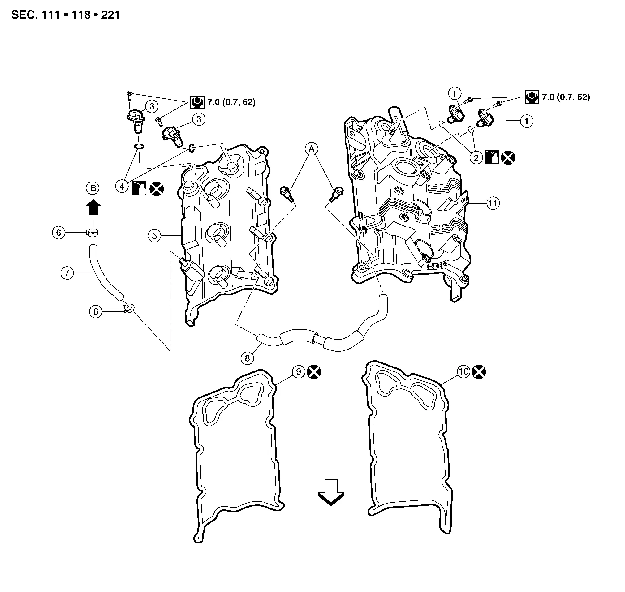
| 1. | Camshaft position sensor (Bank 2) | 2. | O-ring | 3. | Camshaft position sensor (Bank 1) |
| 4. | O-ring | 5. | Rocker cover (Bank 1) | 6. | Clamp |
| 7. | Blow-by hose | 8. | Breather hose | 9. | Rocker cover gasket (Bank 1) |
| 10. | Rocker cover gasket (Bank 2) | 11. | Rocker cover (Bank 2) | A. | Refer to Removal and Installation (Bank 2) (Bank 2) or Removal and Installation (Bank 1) (Bank 1). |
| B. | To air duct hose and resonator assembly. Refer to Exploded View. |
 |
Engine front |
Removal and Installation (Bank 2)
REMOVAL
WARNING:
-
Be sure to read Precaution for Handling High Pressure Fuel System when working on the high pressure fuel system.
-
Put a “CAUTION: FLAMMABLE” sign in the workshop.
-
Be sure to work in a well ventilated area and furnish workshop with a CO2 fire extinguisher.
-
Do not smoke while servicing fuel system. Keep open flames and sparks away from the work area.
Release fuel pressure. Refer to Work Procedure.
Remove high pressure fuel pump. Refer to Removal and Installation.
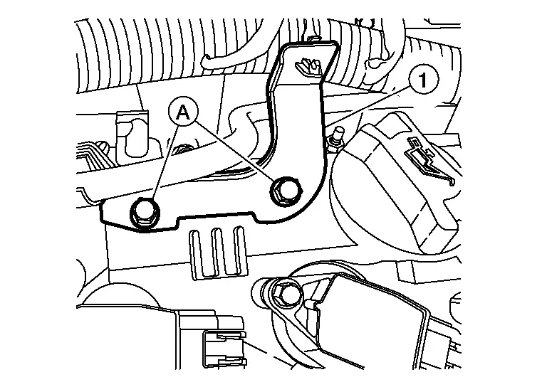
Remove bolts (A) and reposition bracket (1) away from rocker cover (bank 2).
Disconnect the harness connectors from exhaust camshaft position sensor (bank 2) and intake camshaft position sensor (bank 2).
Remove exhaust camshaft position sensor (bank 2) and intake camshaft position sensor (bank 2).

CAUTION:
-
Handle carefully to avoid dropping and shocks.
-
Do not disassemble camshaft position sensor.
-
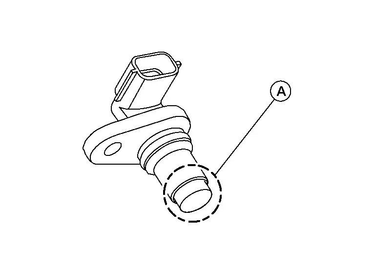
Do not allow metal powder to adhere to magnetic part at sensor tip (A).
-
Do not place sensors in a location where they are exposed to magnetism.
-
Do not reuse O-ring.
Remove ignition coils. Refer to Exploded View.
CAUTION:
Do not shock ignition coils.
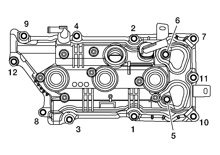
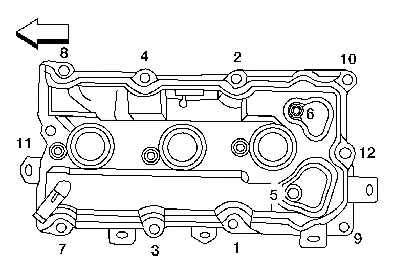
Remove rocker cover bolts in reverse of the sequence shown and remove rocker cover (bank 2).
CAUTION:
Do not reuse rocker cover (bank 2) gasket.
Remove oil filler cap from rocker cover (bank 2) (if necessary).
Disengage clamp and remove blow-by hose from rocker cover (bank 2) (if necessary).
INSTALLATION
Installation is in the reverse order of removal.
CAUTION:
-
Do not reuse rocker cover (bank 2) gasket.
-
Do not reuse camshaft position sensor O-rings.
-
Blow-by hose clamps should be installed facing upwards.
-
Install press fit hoses so that the white mark faces the rib of the connector.
-
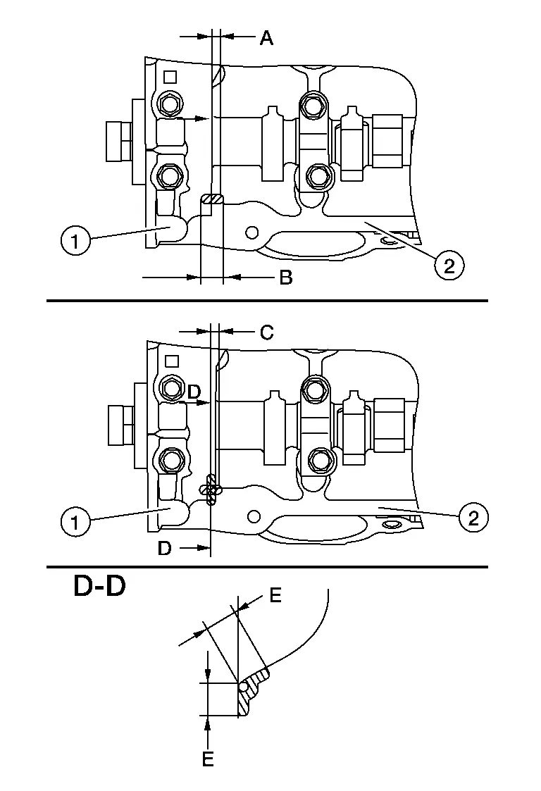
Apply a 3 mm (0.12 mm) bead of sealant to the areas on the front corners using a suitable tool.

-
Use Genuine Silicone RTV Sealant or equivalent. Refer to Recommended Chemical Products and Sealants.
CAUTION:
-
Installation should be done within 5 minutes after applying liquid gasket.
-
Do not fill the engine with engine oil for at least 30 minutes after the components are installed to allow the sealant to cure.
(1) : Camshaft bracket (2) : Cylinder head (A) : 4 mm (0.16 in) (B) : 5 mm (0.20 in) (C) : 4 mm (0.16 in) (E) : 10 mm (0.39 in) -
-
Tighten the rocker cover bolts to the specified torque in the sequence shown.

Rocker cover bolts Step 1 : 1.96 N·m (0.20 kg-m, 17 in-lb) Step 2 : 8.33 N·m (0.85 kg-m, 74 in-lb)
Removal and Installation (Bank 1)
REMOVAL
Remove the front air duct and air duct hose and resonator assembly. Refer to Removal and Installation.
Remove the intake manifold collector. Refer to Removal and Installation.
Disconnect the harness connectors from exhaust camshaft position sensor (bank 1) and intake camshaft position sensor (bank 1).
Remove exhaust camshaft position sensor (bank 1) and intake camshaft position sensor (bank 1).
CAUTION:
-
Handle carefully to avoid dropping and shocks.
-
Do not disassemble camshaft position sensor.
-
Do not allow metal powder to adhere to magnetic part at sensor tip (A).
-
Do not place sensors in a location where they are exposed to magnetism.
-
Do not reuse O-rings.
Remove the breather hose from the rocker cover (bank 1).
Remove ignition coils. Refer to Exploded View.
CAUTION:
Do not shock ignition coils.
Remove rocker cover bolts in reverse of the sequence shown.
 |
: Engine front |
Remove the rocker cover (bank 1) and rocker cover (bank 1) gasket.
CAUTION:
Do not reuse rocker cover (bank 1) gasket.
INSTALLATION
Installation is in the reverse order of removal.
CAUTION:
-
Do not reuse rocker cover (bank 1) gasket or camshaft position sensor O-rings.
-
Blow-by hose clamps should be installed facing upwards.
-
Install press fit hoses so that the white mark faces the rib of the connector.
-
Apply a 3 mm (0.12 mm) bead of sealant to the areas on the front corners using a suitable tool.
-
Use Genuine Silicone RTV Sealant or equivalent. Refer to Recommended Chemical Products and Sealants.
CAUTION:
-
Installation should be done within 5 minutes after applying liquid gasket.
-
Do not fill the engine with engine oil for at least 30 minutes after the components are installed to allow the sealant to cure.
(1) : Camshaft bracket (2) : Cylinder head (A) : 4 mm (0.16 in) (B) : 5 mm (0.20 in) (C) : 4 mm (0.16 in) (E) : 10 mm (0.39 in) -
-
Tighten the rocker cover bolts to the specified torque in the sequence shown.

Rocker cover bolts Step 1 : 1.96 N·m (0.20 kg-m, 17 in-lb) Step 2 : 8.33 N·m (0.85 kg-m, 74 in-lb) 
: Engine front

Nissan Pathfinder (R53) 2022-2026 Service Manual
Contact Us
Nissan Pathfinder Info Center
Email: info@nipathfinder.com
Phone: +1 (800) 123-4567
Address: 123 Pathfinder Blvd, Nashville, TN 37214, USA
Working Hours: Mon–Fri, 9:00 AM – 5:00 PM (EST)
