Nissan Pathfinder: Removal and Installation - Valve Timing Control ++
Exploded View
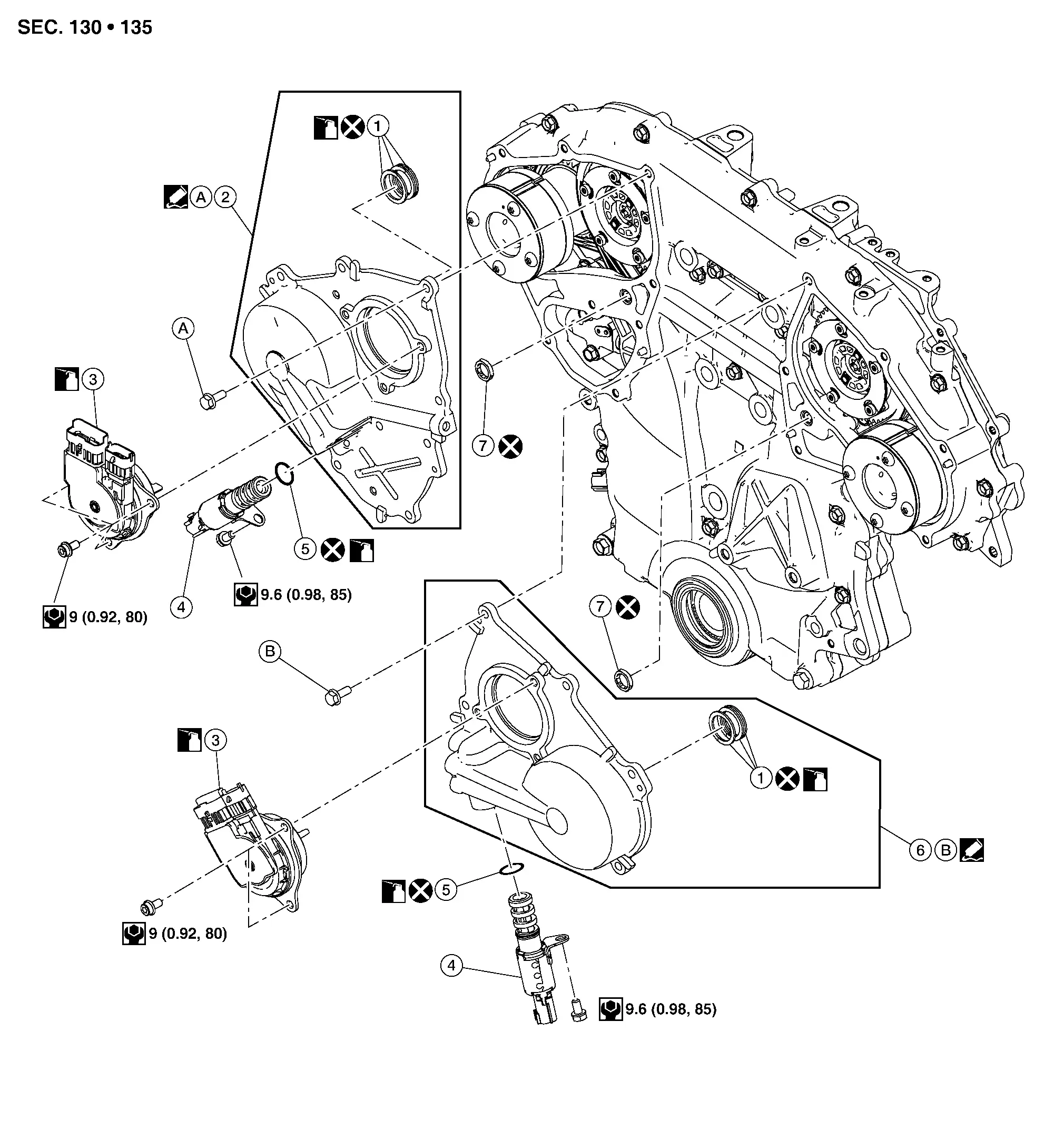
| 1. | O-ring | 2. | Valve timing control cover (bank 1) | 3. | Electric intake valve timing control actuator |
| 4. | Exhaust valve timing control solenoid valve | 5. | O-ring | 6. | Valve timing control cover (bank 2) |
| 7. | O-ring | A. | Refer to Valve Timing Control Cover (bank 1) . | B. | Refer to Valve Timing Control Cover (bank 2) . |
Valve Timing Control Cover (bank 1)
REMOVAL
Disconnect battery negative terminal. Refer to Battery Disconnect.
Remove reservoir tank. Refer to Exploded View.
Disconnect the harness connectors from electric intake valve timing control actuator.
Disconnect the harness connector from exhaust valve timing control solenoid valve.
Remove electric intake valve timing control actuator and exhaust valve timing control solenoid valve from valve timing control cover (bank 1).
CAUTION:
Do not reuse exhaust valve timing control solenoid valve O-ring.
Remove the intake valve timing control cover [bank 1 (A)].
-
Loosen the intake valve timing control cover [bank 1 (A)] bolts in reverse of the sequence shown.
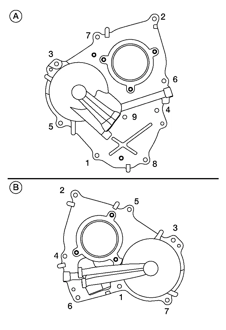
(B) : Bank 2
INSTALLATION
Using a suitable tool, remove old liquid gasket from mating surfaces.
Install the O-rings to the front timing chain case.
CAUTION:
Do not reuse O-ring.
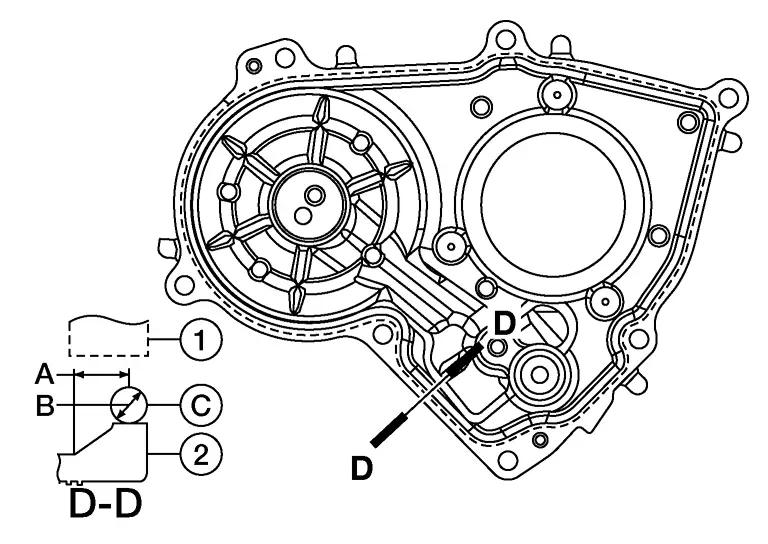
Install the valve timing control cover (bank 1) using the following procedure:Install the O-rings (1) to the valve timing control cover (bank 1).
CAUTION:
Do not reuse O-rings.
 NOTE:
NOTE:
-
Lubricate O-rings with clean engine oil before installing valve timing control cover (bank 1).
-
Verify O-rings are installed into grooves in valve timing control cover correctly.
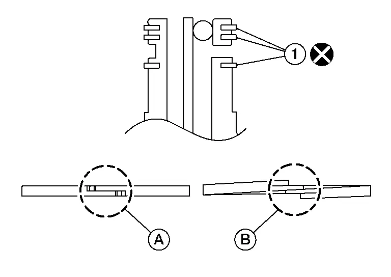
(A) : OK (B) : NG
CAUTION:
-
The components must be installed within 5 minutes of the liquid gasket application.
-
Do not re-tighten bolts after the 5 minutes have elapsed.
-
Then allow 30 minutes for the liquid gasket to set before adding oil to the engine.
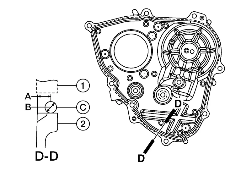
Use Genuine Silicone RTV Sealant or equivalent. Refer to Recommended Chemical Products and Sealants.
| (1) | : Front timing chain case |
| (A) | : 4.0 - 5.6 mm (0.157 - 0.220 in) |
| (B) | : 3.4 - 4.4 mm (0.134 - 0.173 in) |

| Bolts | : 11.3 N·m (1.2 kg-m, 8 ft-lb) |
| (B) | : Bank 2 |
Installation of the remaining components is in the reverse order of removal.
CAUTION:
Perform ELECTRIC IVT CONTROL ACTUATOR POSITION LEARNING. Refer to Description.
Valve Timing Control Cover (bank 2)
REMOVAL
Disconnect the harness connectors from electric intake valve timing control actuator.
Disconnect the harness connector from exhaust valve timing control solenoid valve.
Remove electric intake valve timing control actuator and exhaust valve timing control solenoid valve from valve timing control cover (bank 2).
CAUTION:
Do not reuse O-ring.
Remove the intake valve timing control cover [bank 2 (B)].
-
Loosen the intake valve timing control cover [bank 2 (B)] bolts in reverse of the sequence shown.

(A) : Bank 1
INSTALLATION
Using a suitable tool, remove old liquid gasket from mating surfaces.
Install the O-rings to the front timing chain case.
CAUTION:
Do not reuse O-ring.
Install the valve timing control cover (bank 2) using the following procedure:Install the O-rings (1) to the valve timing control cover (bank 2).
CAUTION:
Do not reuse O-rings.
 NOTE:
NOTE:
-
Lubricate O-rings with clean engine oil before installing valve timing control cover (bank 1).
-
Verify O-rings are installed into grooves in valve timing control cover correctly.

(A) : OK (B) : NG
CAUTION:
-
The components must be installed within 5 minutes of the liquid gasket application.
-
Do not re-tighten bolts after the 5 minutes have elapsed.
-
Then allow 30 minutes for the liquid gasket to set before adding oil to the engine.
Use Genuine Silicone RTV Sealant or equivalent. Refer to Recommended Chemical Products and Sealants.
| (1) | : Front timing chain case |
| (A) | : 4.0 - 5.6 mm (0.157 - 0.220 in) |
| (B) | : 3.4 - 4.4 mm (0.134 - 0.173 in) |

| Bolts | : 11.3 N·m (1.2 kg-m, 8 ft-lb) |
| (A) | : Bank 1 |
Installation of the remaining components is in the reverse order of removal.
CAUTION:
Perform ELECTRIC IVT CONTROL ACTUATOR POSITION LEARNING. Refer to Description.

Nissan Pathfinder (R53) 2022-2026 Service Manual
Contact Us
Nissan Pathfinder Info Center
Email: info@nipathfinder.com
Phone: +1 (800) 123-4567
Address: 123 Pathfinder Blvd, Nashville, TN 37214, USA
Working Hours: Mon–Fri, 9:00 AM – 5:00 PM (EST)
