Nissan Pathfinder: Removal and Installation - Camshaft ++
Exploded View
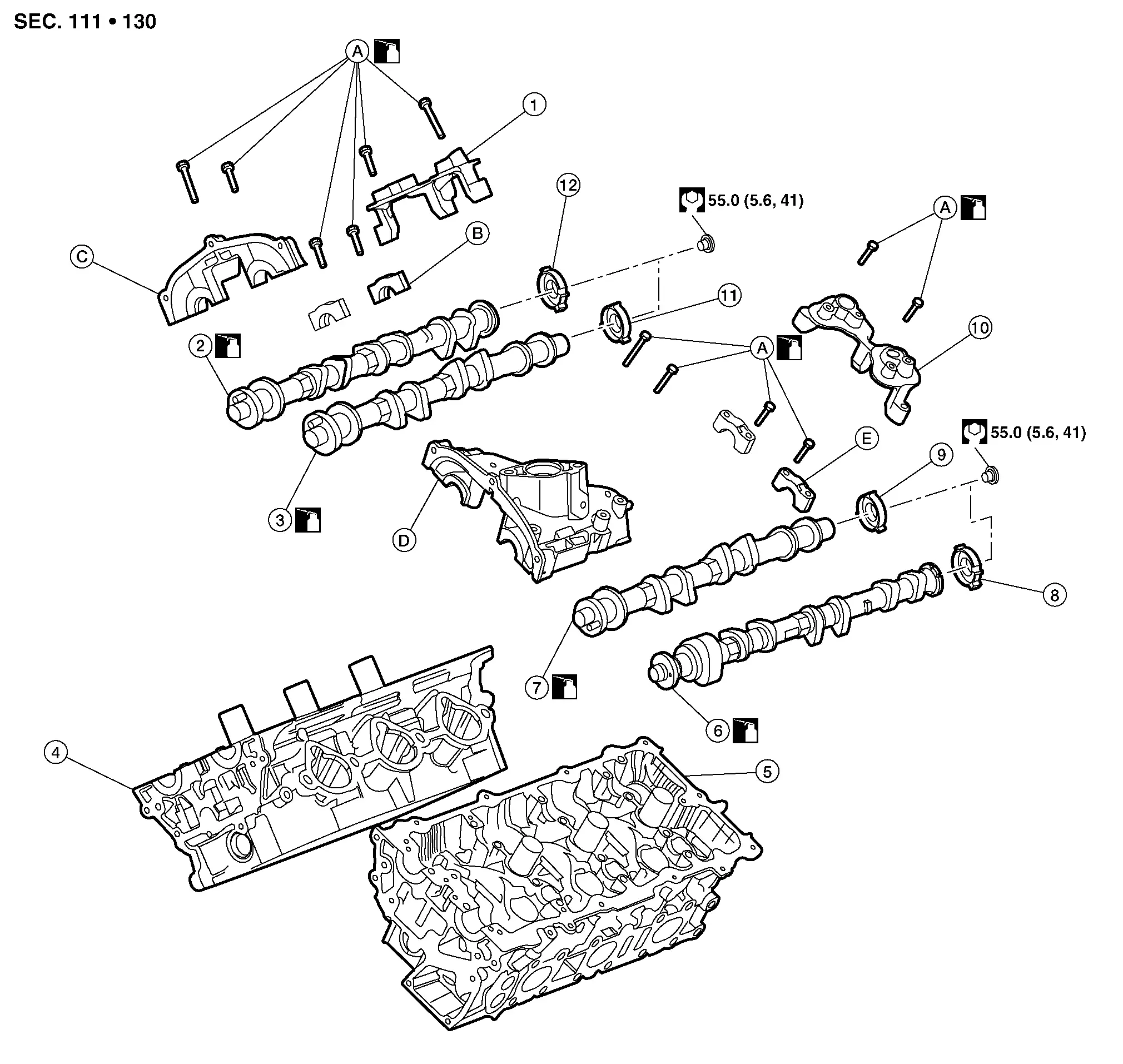
| 1. | Camshaft position sensor bracket (Bank 1) | 2. | Camshaft [bank 1 (EXH)] | 3. | Camshaft [bank 1 (INT)] |
| 4. | Cylinder head (bank 1) | 5. | Cylinder head (bank 2) | 6. | Camshaft [bank 2 (EXH)] |
| 7. | Camshaft [bank 2 (INT)] | 8. | Signal plate [bank 2 (EXH)] | 9. | Signal plate [bank 2 (INT)] |
| 10. | Camshaft position sensor bracket (Bank 2) | 11. | Signal plate [bank 1 (INT)] | 12. | Signal plate [bank 1 (EXH)] |
| A. | Refer to Removal and Installation. | B. | Camshaft bracket (Bank 1) | C. | No. 1 camshaft bracket (Bank 1) |
| D. | No. 1 camshaft bracket (Bank 2) | E. | Camshaft bracket (Bank 2) |
CAUTION:
Apply new engine oil to parts marked in illustration before installation.
Removal and Installation
REMOVAL
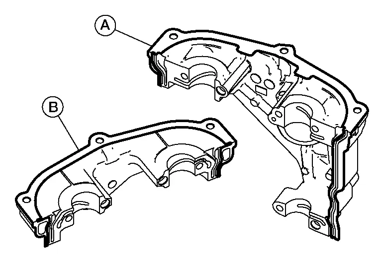
Remove the rear timing chain case. Refer to Removal and Installation.
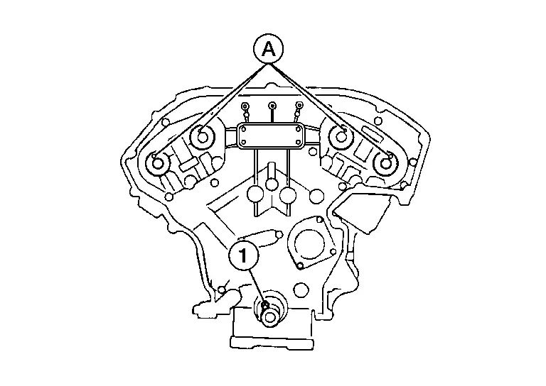
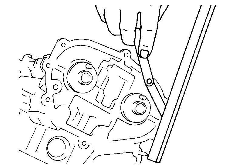
Remove camshaft position sensor bracket bolts in reverse of the sequence shown and remove the camshaft sensor brackets.

 NOTE:
NOTE:
Bank 2 shown, Bank 1 similar.
 |
: Engine front |
Remove the lifter. Refer to Exploded View.
Loosen bolts in reverse of the sequence shown and remove the intake, exhaust camshaft brackets and the camshafts.
-
Mark the camshafts, camshaft brackets, and bolts so they are placed in the same position and direction for installation.
-
Equally loosen the camshaft bracket bolts in several steps in the reverse order as shown.
-
Cylinder head (bank 1)
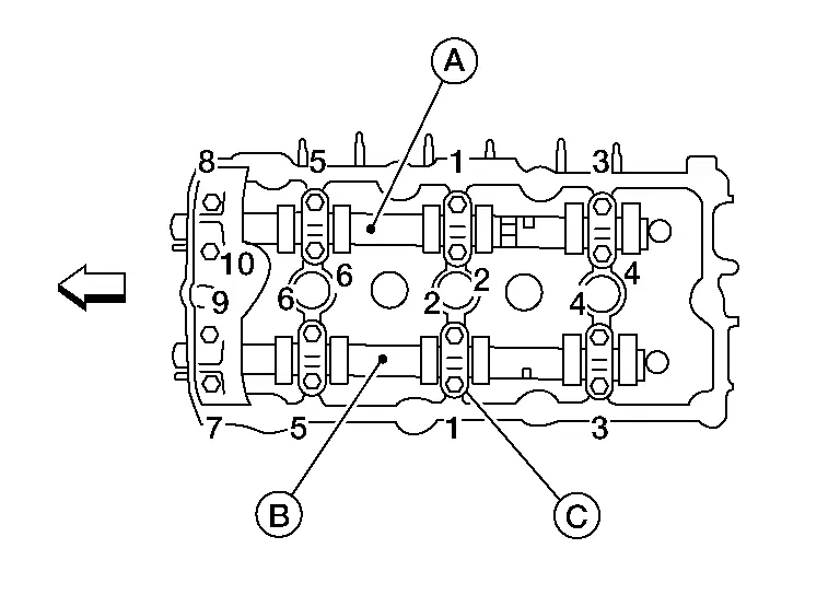
(A) : Camshaft [bank 1 (EXH)] (B) : Camshaft [bank 1 (INT)] (C) : Camshaft bracket 
: Engine front -
Cylinder head (bank 2)
Remove valve lifters (if necessary).
 NOTE:
NOTE:
Identify installation positions to ensure proper installation.
After removal of camshafts, inspect camshafts and corresponding parts for wear. Refer to Inspection After Removal.
INSTALLATION
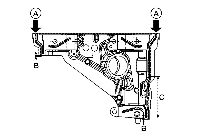
Before installation, remove any old liquid gasket from component mating surfaces using a suitable tool.
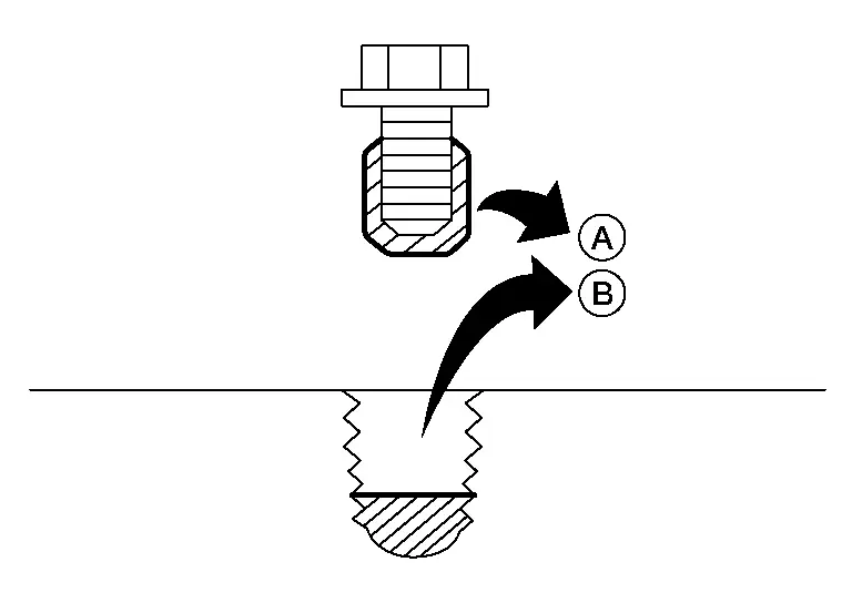
-
Remove the old liquid gasket from the bolt holes (B) and threads (A).
-
Do not scratch or damage the mating surfaces.
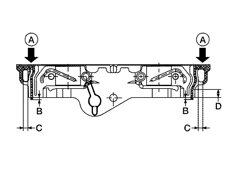
Before installing the No. 1 camshaft bracket, remove the old liquid gasket from the mating surface using a suitable tool.
| (A) | : Camshaft bracket No. 1 (bank 2) |
| (B) | : Camshaft bracket No. 1 (bank 1) |
-
Do not scratch or damage the mating surface.
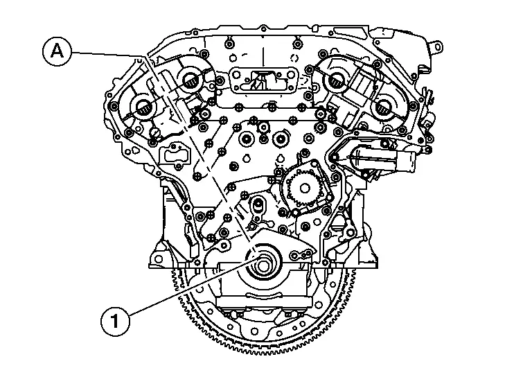
Turn the crankshaft until No. 1 piston is set at TDC on the compression stroke.
-
The crankshaft key (1) should line up with the right bank cylinder center line (A) as shown.
Install valve lifters (if removed).
 NOTE:
NOTE:
Install them in original positions.
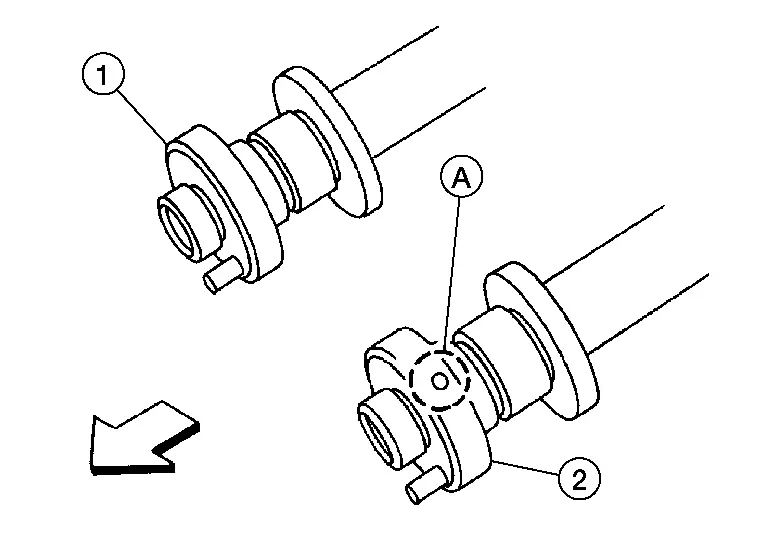
Install exhaust and intake camshafts and camshaft brackets.
-
Intake camshaft (2) has a drill mark (A) on camshaft sprocket mounting flange.
(1) : Exhaust camshaft 
: Engine front -
Follow your identification marks made during removal or follow the identification marks that are present on the new camshafts components for proper placement and direction of the components.
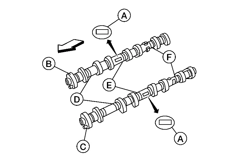
Bank INT/EXH ID mark (A) Drill mark Paint marks M1 (E) M2 (F) M3 (D) RH (B) INT 4F Yes Blue No Green EXH 4H No No Green Green LH (C) INT 4G Yes Blue No Green EXH 4K No No Green Green -
Position the camshaft dowel pins (A) as shown.
(1) : Crankshaft keyway
Install the camshaft brackets using the following procedure:Apply a 2.0 - 3.0 mm (0.079 - 0.118 in) bead of liquid gasket to the No. 1 camshaft bracket (bank 1) and No. 1 camshaft bracket (bank 2) as shown.
CAUTION:
-
Installation should be done within 5 minutes after applying liquid gasket.
-
Do not fill the engine with engine oil for at least 30 minutes after the components are installed to allow the liquid gasket to cure.
Use Genuine Silicone RTV Sealant or equivalent. Refer to Recommended Chemical Products and Sealants.
-
No. 1 camshaft bracket (bank 1)
 NOTE:
NOTE:
-
Remove liquid gasket that protrudes at location (A).
-
Remove liquid gasket that protrudes within range of 8.5 mm (0.335 in) (D) from rear face of No. 1 camshaft bracket (bank 1).
(B) : 2 mm (0.08 in) (C) : 5 mm (0.20 in) -
-
No. 1 camshaft bracket (bank 2)
 NOTE:
NOTE:
-
Remove liquid gasket that protrudes at location (A).
-
Remove liquid gasket that protrudes within range of 67 mm (2.64 in) (C) from rear face of No. 1 camshaft bracket (bank 2).
(B) : 2 mm (0.08 in) -
| (A) | : Camshaft bracket ID mark |
| (B) | : Bank 1 |
| (C) | : Bank 2 |
 |
: Engine front |
-
Cylinder head (bank 1)

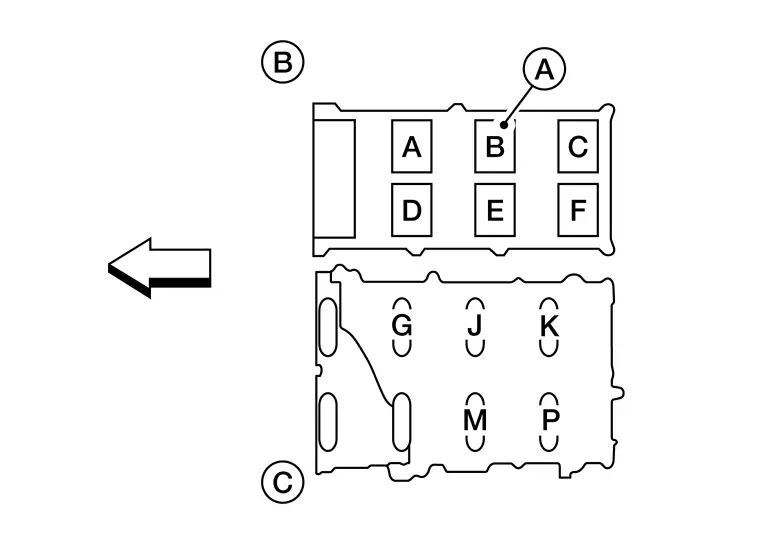
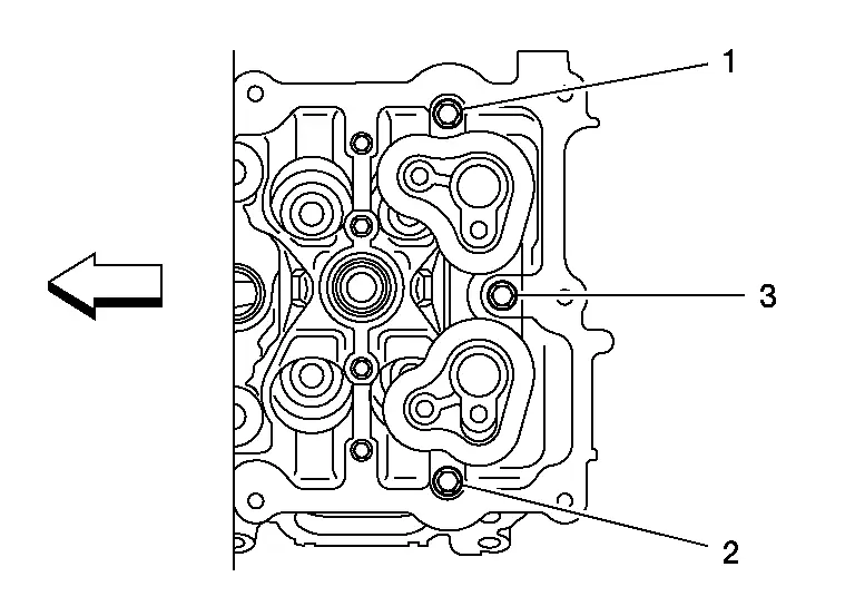
Step 1 1.96 N·m (0.20 kg-m, 17 in-lb) Tighten No. 7 - 10, then tighten No. 1 - 6 in the sequence shown. Step 2 5.88 N·m (0.60 kg-m, 52 in-lb) Tighten No. 1 - 10 in the sequence shown. Step 3 10.41 N·m (1.1 kg-m, 8 ft-lb) Tighten No. 1 - 10 in the sequence shown. (A) : Camshaft [bank 1 (EXH)] (B) : Camshaft [bank 1 (INT)] (C) : Camshaft bracket 
: Engine front -
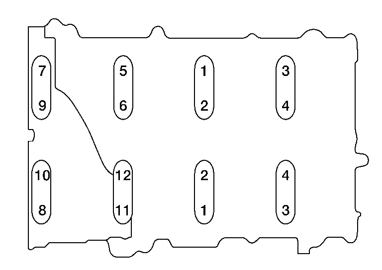
Cylinder head (bank 2)

Step 1 1.96 N·m (0.20 kg-m, 17 in-lb) Tighten No. 7 - 12, then tighten No. 1 - 6 in the sequence shown. Step 2 5.88 N·m (0.60 kg-m, 52 in-lb) Tighten No. 1 - 12 in the sequence shown. Step 3 10.41 N·m (1.1 kg-m, 8 ft-lb) Tighten No. 1 - 12 in the sequence shown.
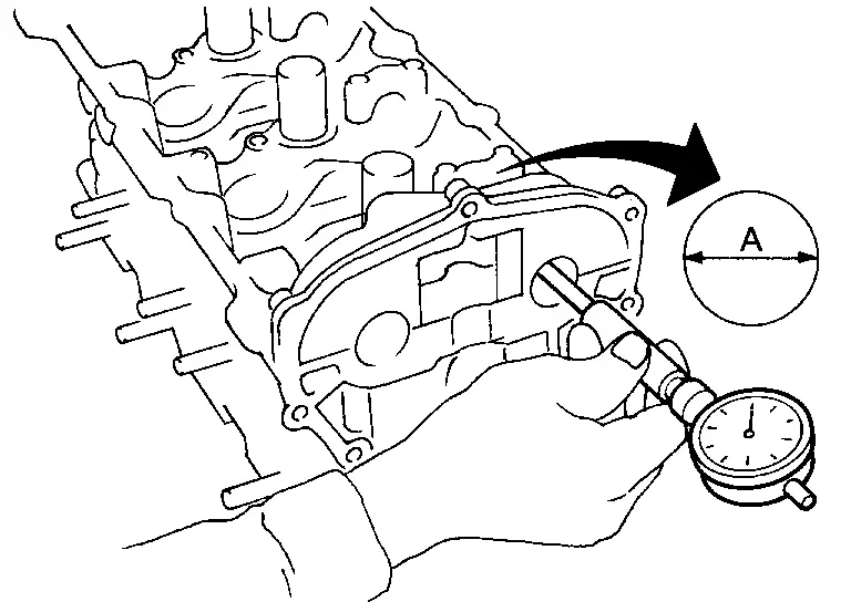
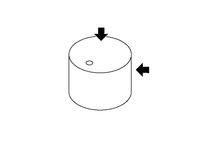
Measure difference in levels between front end faces of No. 1 camshaft bracket and cylinder head.
| Standard | : – 0.14 to 0.14 mm (– 0.0055 to 0.0055 in) |
-
If measurement is outside the specified range, re-install camshaft and camshaft bracket.
Install camshaft position sensor bracket (Bank 1 and Bank 2) and tighten to specified torque in sequence shown.
| Bolts 1 - 3 | : 10.4 N·m (1.1 kg-m, 8 ft-lb) |
 |
: Engine front |
Installation of the remaining components is in the reverse order of removal.
INSPECTION AFTER INSTALLATION
-
Before starting engine, check oil/fluid levels including engine coolant and engine oil. If there is less than required quantity, fill to the specified level. Refer to Fluids and Lubricants (FOR USA AND CANADA) or Fluids and Lubricants (FOR MEXICO).
-
Use procedure below to check for fuel leaks.
-
Place ignition switch in the "ON" position (with engine stopped). With fuel pressure applied to fuel piping, check for fuel leaks at connection points.
-
Start engine. With engine speed increased, check again for fuel leaks at connection points.
-
Run engine to check for unusual noise and vibration.
 NOTE:
NOTE:
If hydraulic pressure inside timing chain tensioner drops after removal and installation, slack in the guide may generate a pounding noise during and just after engine start. However, this is normal. Noise will stop after hydraulic pressure rises.
-
Warm up engine thoroughly to make sure there are no leaks of fuel, exhaust gas, or any oils/fluids including engine oil and engine coolant.
-
Bleed air from passages in lines and hoses, such as in cooling system.
-
After cooling down engine, again check oil/fluid levels including engine oil and engine coolant. Refill to specified level, if necessary.
-
Summary of the inspection items:
Item Before starting engine Engine running After engine stopped Engine coolant Level Leakage Level Engine oil Level Leakage Level Transmission/transaxle fluid A/T and CVT Models Leakage Level/Leakage Leakage M/T Models Level/Leakage Leakage Level/Leakage Other oils and fluids* Level Leakage Level Fuel Leakage Leakage Leakage Exhaust gas — Leakage — *Power steering fluid, brake fluid, etc.
Inspection After Removal
Camshaft Visual Check
Check camshaft for scratches and wear. Replace if necessary.
Camshaft Runout
-
Put V-block on precise flat bed and support No. 2 and No. 4 journal of camshaft as shown.
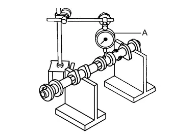
-
Set dial gauges vertically to No. 3 journal as shown.
-
Turn camshaft in one direction slowly by hand measure the camshaft runout on the dial gauges.
-
Runout is the largest indicator reading after one full revolution.
Camshaft Runout Standard and Limit : Refer to Camshaft.
-
-
If actual runout exceeds the limit, replace the camshaft.
Camshaft Lobe Height
-
Measure camshaft lobe height as shown. Refer to Camshaft.
-
If wear has reduced the camshaft lobe height below specifications, replace the camshaft.
Camshaft Journal Clearance
-
Outer Diameter of Camshaft Journal
-
Measure outer diameter of camshaft journal as shown.
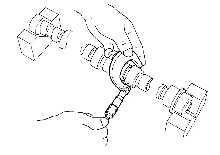
Standard : Refer to Camshaft.
-
-
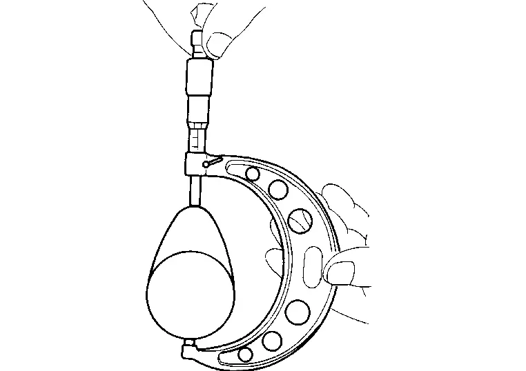
Inner Diameter of Camshaft Bracket
-
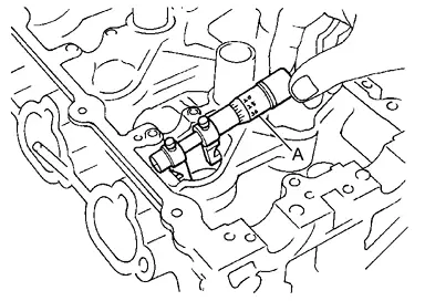
Tighten camshaft bracket bolt with specified torque.
-
Using inside micrometer, measure inner diameter (A) of camshaft bracket.
Standard : Refer to Camshaft.
-
-
Calculation of Camshaft Journal Clearance
-
(Journal clearance) = (inner diameter of camshaft bracket) – (outer diameter of camshaft journal)
Standard and Limit : Refer to Camshaft. -
When out of the specified range, replace either or both camshaft and cylinder head.
 NOTE:
NOTE:
Inner diameter of camshaft bracket is manufactured together with cylinder head. Replace the whole cylinder head assembly.
-
-
Camshaft End Play
-
Install the camshaft in the cylinder head.
-
Install dial gauge in thrust direction on front end of camshaft. Measure end play when camshaft is moved forward/backward (in direction to axis) as shown.
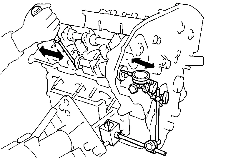
Standard and Limit : Refer to Camshaft.
-
If out of the specified range, replace with new camshaft and measure again.
-
If out of the specified range again, replace with new cylinder head.
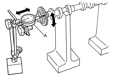
Camshaft Sprocket Runout
-
Put V-block on precise flat bed and support No. 2 and No. 4 journal of camshaft as shown.
-
Install camshaft sprocket on camshaft.
-
Measure camshaft sprocket runout.
Standard : Refer to Camshaft. -
If sprocket runout exceeds the limit, replace camshaft sprocket.
Valve Lifter
-
Check if the surface of the valve lifter has any excessive wear or cracks replace as necessary.
Valve Lifter Clearance
-
Outer Diameter of Valve Lifter
-
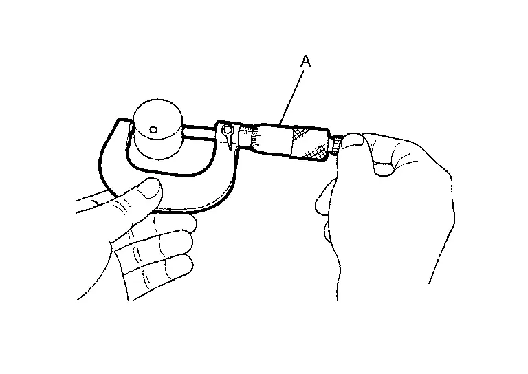
Using a suitable tool (A), measure the outer diameter of the valve lifter. Refer to Camshaft.
-
If out of the specified range, replace the valve lifter.
-
-
Valve Lifter Bore Diameter
-
Using inside micrometer, measure diameter of valve lifter bore of cylinder head. Refer to Camshaft.
-
If out of the specified range, replace the cylinder head assembly.
-
-
Calculation of Valve Lifter Clearance
-
(Valve lifter clearance) = (valve lifter bore diameter) – (valve lifter outer diameter) Refer to Camshaft.
-
If out of specified range, replace either or both valve lifter and cylinder head assembly.
-

Nissan Pathfinder (R53) 2022-2026 Service Manual
Contact Us
Nissan Pathfinder Info Center
Email: info@nipathfinder.com
Phone: +1 (800) 123-4567
Address: 123 Pathfinder Blvd, Nashville, TN 37214, USA
Working Hours: Mon–Fri, 9:00 AM – 5:00 PM (EST)
