Nissan Pathfinder: Removal and Installation - Front Timing Chain Case ++
Exploded View
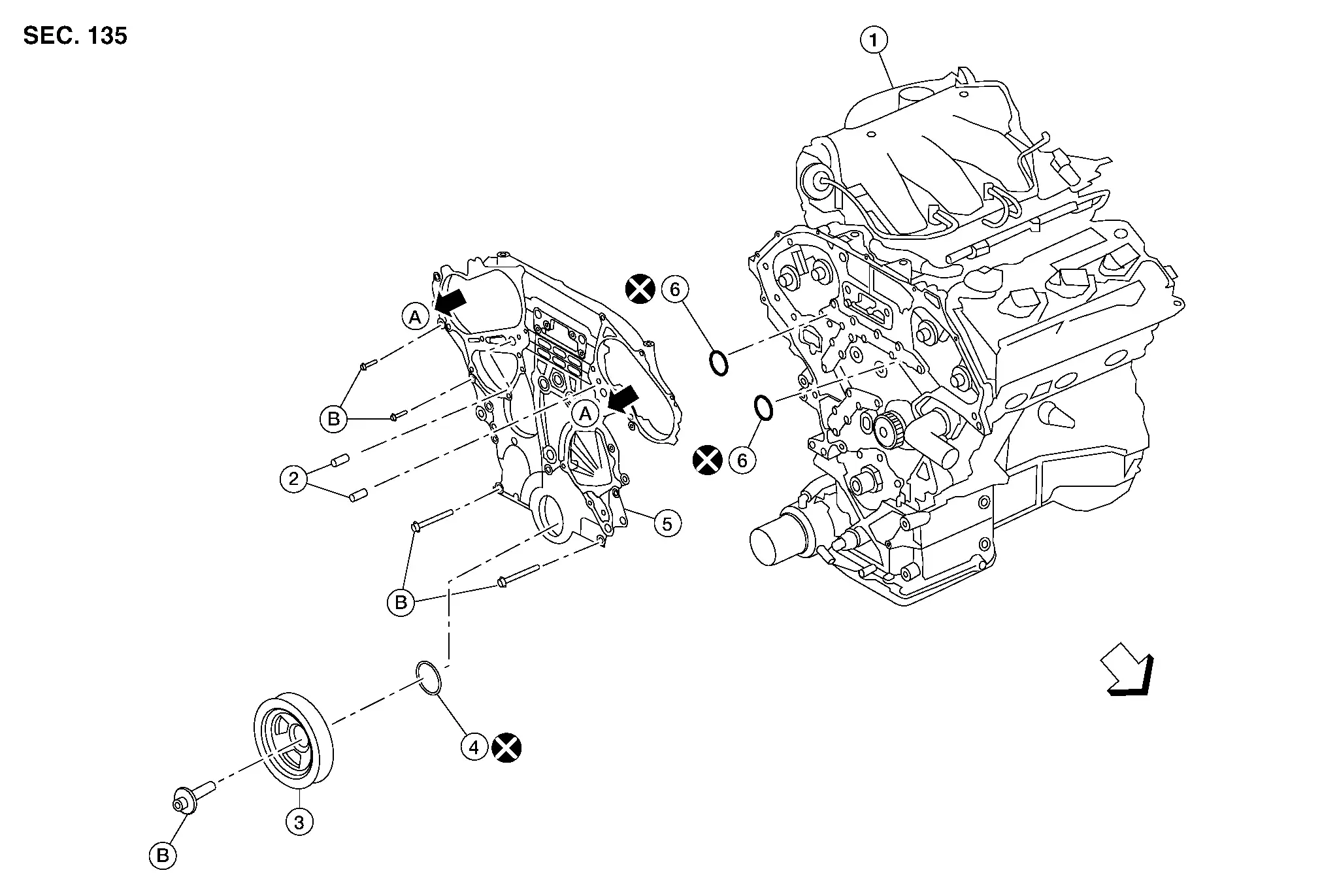
| 1. | Engine assembly | 2. | Front timing chain case oil filter | 3. | Crankshaft pulley |
| 4. | Front oil seal | 5. | Front timing chain case | 6. | O-ring |
| A. | To valve timing control cover (bank 1/bank 2). Refer to Exploded View. | B. | Refer to Removal and Installation. |
 |
Front |
Removal and Installation
 NOTE:
NOTE:
When removing components such as hoses, tubes/lines, etc., cap or plug openings to prevent fluid from spilling.
Remove and secure engine assembly to stand. Refer to Setting.
If removing the timing chains, obtain compression TDC of No. 1 cylinder as follows:Disconnect the vacuum hose from intake manifold collector. Refer to Exploded View. Disconnect the engine mount insulator (front) vacuum hose. Refer to Exploded View. Disconnect VIAS control solenoid valve harness connectors. Refer to Component Parts Location. Disconnect the harness connector from the electronic controlled engine mount control solenoid valve. Remove the electronic controlled engine mount control solenoid valve. Refer to Component Parts Location. Remove the EVAP canister purge volume control solenoid valve hose. Refer to Exploded View. Disconnect the EVAP canister purge volume control solenoid valve harness connector. Refer to Exploded View. Disconnect electronic throttle control actuator harness connector. Refer to Exploded View. Disconnect PCV hose from intake manifold collector. Loosen the intake manifold collector bolts and nuts in reverse of the sequence shown and then remove the intake manifold collector and intake manifold collector gasket.

CAUTION:
Do not reuse intake manifold collector gasket.
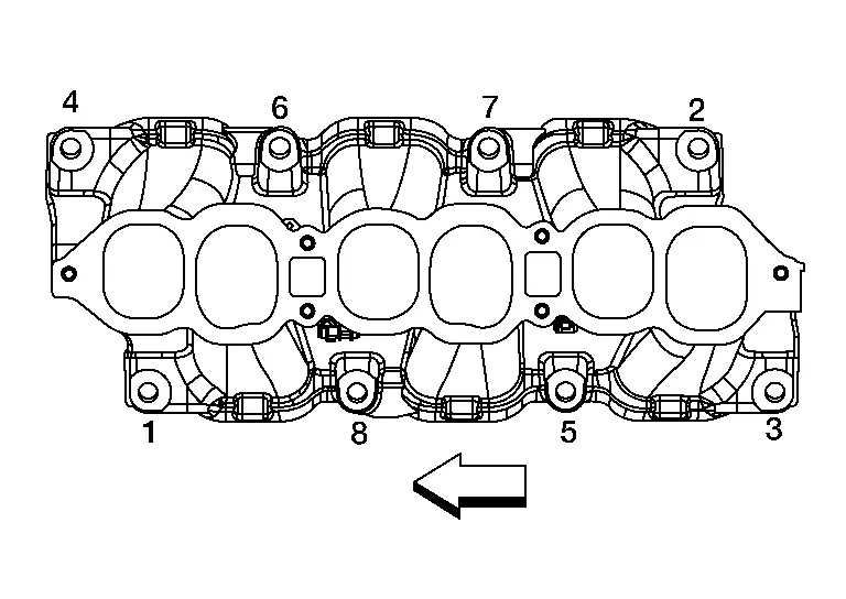
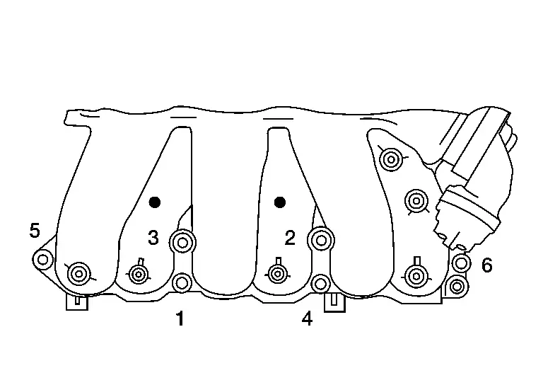
Loosen intake manifold nuts and bolts in reverse of the sequence shown.
 |
: Engine front |
CAUTION:
Do not reuse intake manifold gasket.
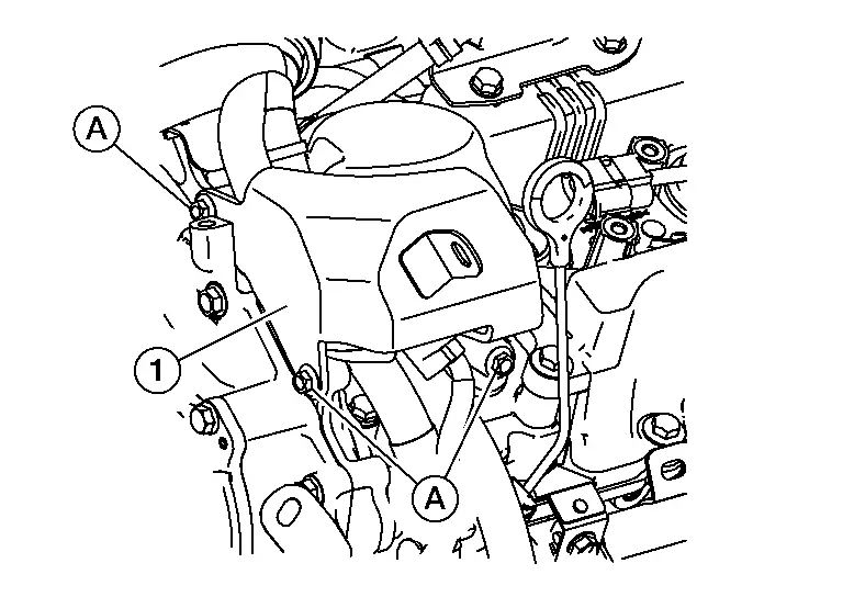
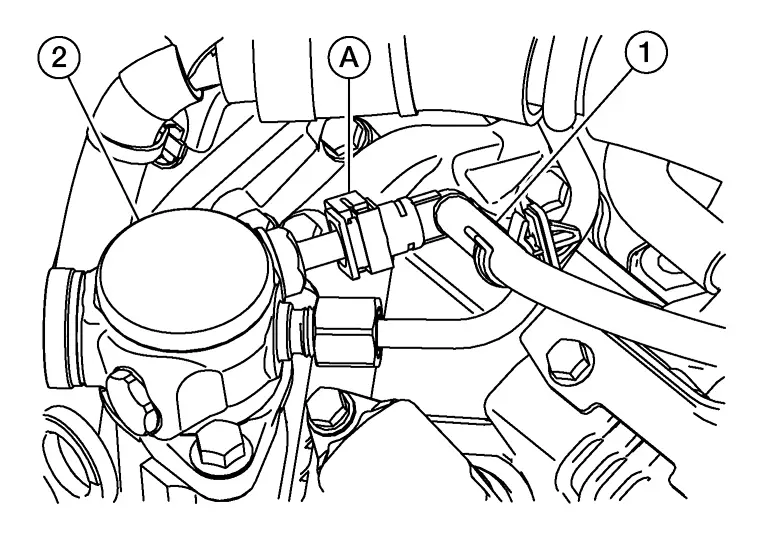
Remove intake manifold studs (if necessary). Remove bolts (A) and remove high pressure fuel pump cover (1).

CAUTION:
Do not reuse high pressure fuel tube (pump side).
Disconnect the harness connector from the high pressure fuel pump. Loosen high pressure fuel pump bolts while alternating sides frequently and remove high pressure fuel pump.CAUTION:
-
Do not reuse O-ring.
-
Do not disassemble plunger on bottom of high pressure fuel pump.
CAUTION:
Do not reuse O-rings.
Remove ignition coils. Refer to Exploded View.CAUTION:
Do not shock ignition coils.
Loosen rocker cover bolts in reverse of the sequence shown.-
Rocker cover (bank 2)

-
Rocker cover (bank 1)

: Engine front
CAUTION:
Do not reuse rocker cover gasket (bank 2/bank 1).
Rotate crankshaft pulley clockwise to align timing mark (grooved line without color) with timing indicator (A).
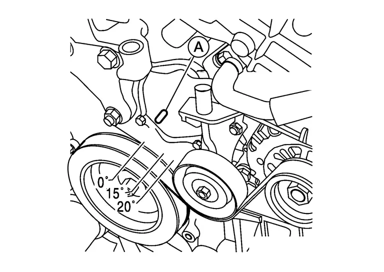
 |
: Engine front |
-
If not, turn the crankshaft one revolution (360°) and align as shown.
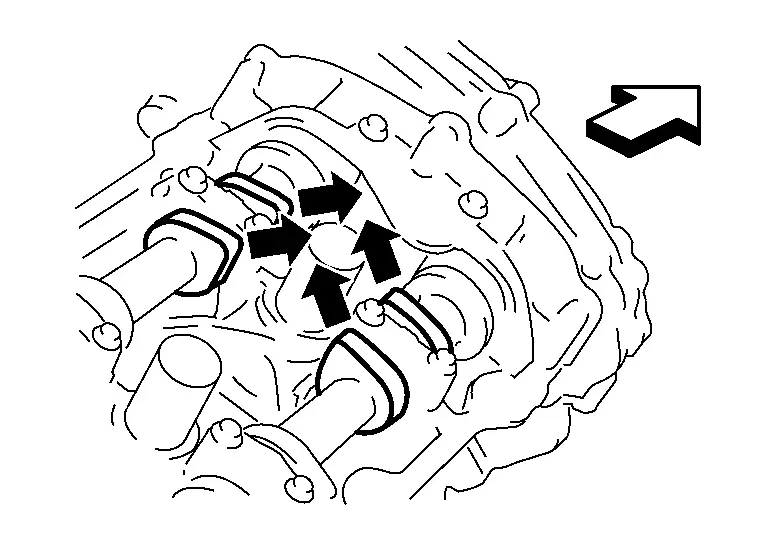
 NOTE:
NOTE:
The graphic shows the bank 1 of the engine. The camshaft lobes on the bank 2 are clocked differently.
While securely holding the hexagonal part in pulley center of drive belt auto-tensioner, move in the direction of arrow (loosening direction of drive belt auto-tensioner) using suitable tool.
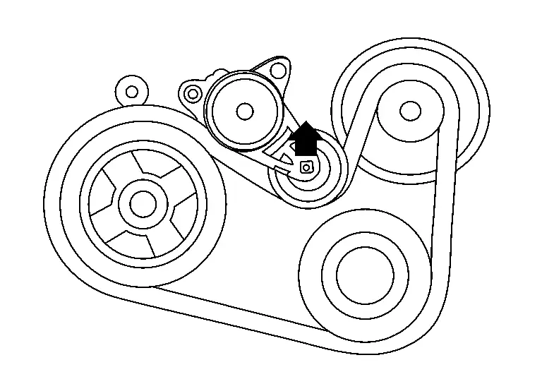
WARNING:
Avoid placing hand in a location where pinching may occur if the holding tool accidentally comes off.
CAUTION:
Do not loosen the drive belt auto-tensioner pulley bolt. (Do not turn it counterclockwise. If turned counterclockwise, the complete drive belt auto-tensioner must be replaced as a unit, including pulley.)
Insert a rod approximately 6 mm (0.24 in) in diameter through the rear of drive belt auto-tensioner into retaining boss to lock drive belt auto-tensioner pulley.
 NOTE:
NOTE:
Leave drive belt auto-tensioner pulley arm locked until drive belt is installed.
Remove drive belt from crankshaft pulley and then remove it from the other pulleys.
Disconnect the harness connectors from the compressor.
Remove the compressor. Refer to Exploded View.
Remove "B" terminal nut and disconnect "B" terminal harness.
Disconnect the harness connector from generator.
Remove the generator. Refer to Exploded View.
Remove the crankshaft pulley as follows:
-
Secure crankshaft pulley with a suitable tool.
-
Loosen crankshaft pulley bolt and locate bolt seating surface at 10 mm (0.39 in) from its original position.
-
Position a suitable tool at recess hole of crankshaft pulley to remove crankshaft pulley.
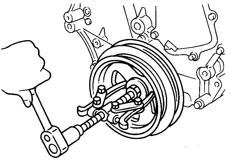
CAUTION:
Do not use a puller claw on the outer diameter of the crankshaft pulley.
Disconnect the harness connector from the engine oil pressure sensor and engine oil temperature sensor.
Remove water pipe. Refer to Exploded View.
Disconnect the water hoses from the oil cooler.
Loosen the oil pan (lower) bolts in reverse of the sequence shown.

Remove the oil pan (lower).
CAUTION:
Do not damage the mating surfaces.
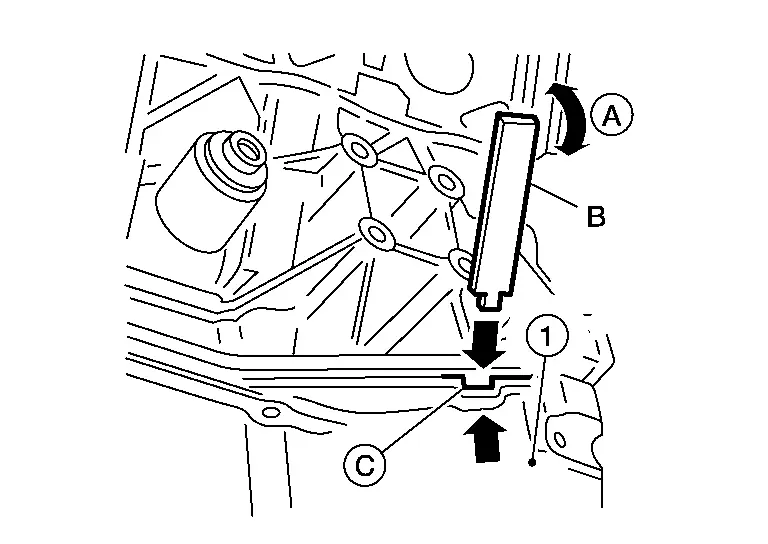
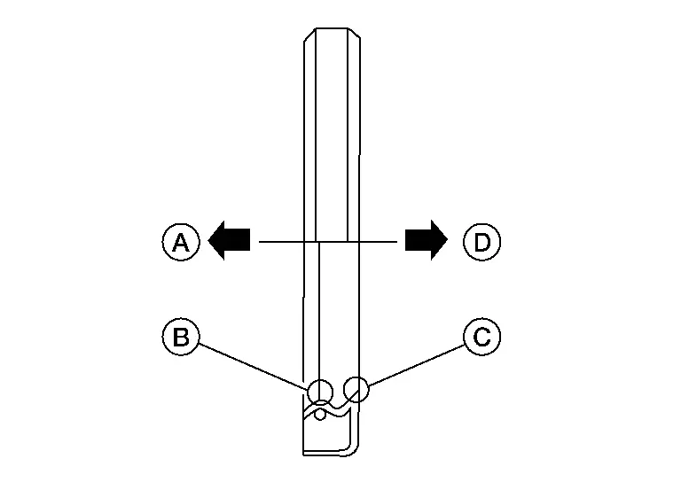
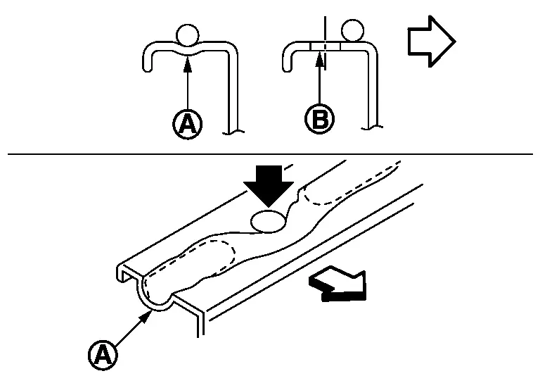
-
After removing the bolts, separate the mating surface and remove the old liquid gasket using Tool (A).
-
Tap (B) the Tool to insert it.
-
In areas where the Tool is difficult to use, lightly tap (C) to slide it.
Tool number (A) : KV10111100 (NI-37228)
Remove the old sealant from the bolt holes and threads.
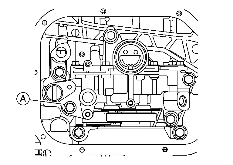
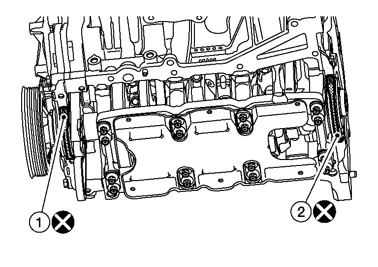
Disconnect the harness connector from the engine oil pressure control solenoid valve.
Remove bolts (B) and remove engine oil pressure control solenoid valve (2).
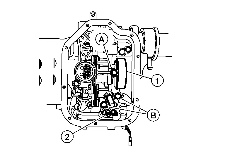
CAUTION:
Do not reuse engine oil pressure control solenoid valve.
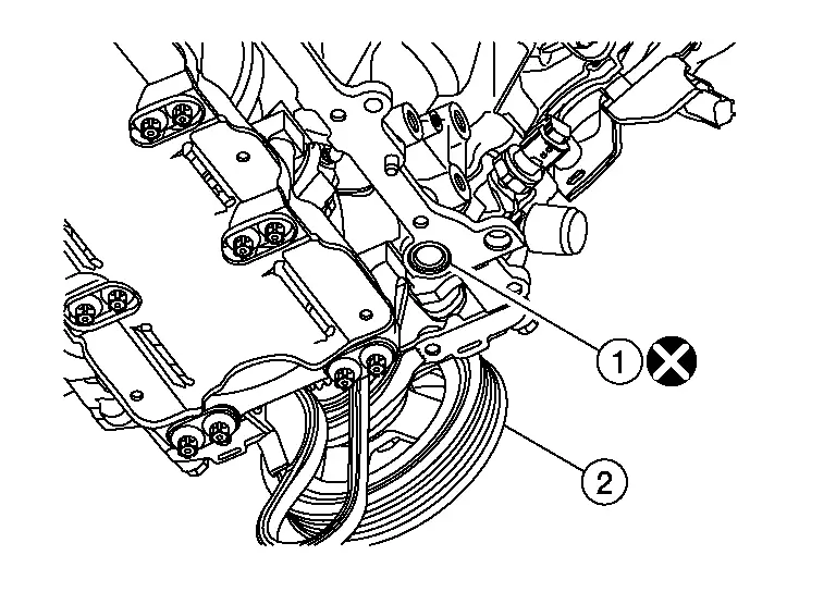
Remove bolt (A) and remove oil pump drive chain cover (1).
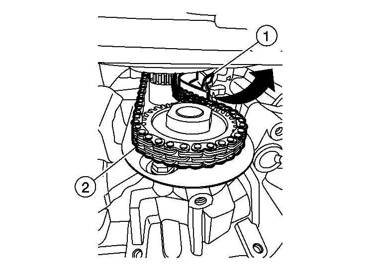
Rotate oil pump drive chain tensioner (1) counterclockwise with a suitable tool and remove oil pump drive chain (2) from oil pump gear.
Remove the oil pump bolts (A) in reverse of the sequence shown and remove (if necessary).
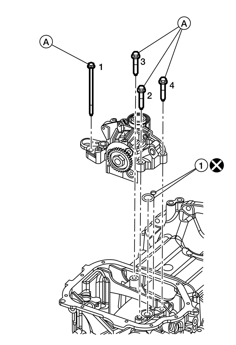
CAUTION:
Do not reuse O-rings (1).
 NOTE:
NOTE:
If removal of oil pump is not necessary, remove bolt (A) before removing oil pan (upper).
Remove the oil pan (upper) using the following procedure:Remove the oil pan (upper) bolts in reverse of the sequence shown.
Remove the O-ring from the bottom of the cylinder block and oil pump housing.
CAUTION:
Do not reuse O-ring.
Remove front cover gasket and rear oil seal retainer gasket.
CAUTION:
Do not reuse front cover gasket or rear oil seal retainer gasket.
Remove the old sealant from the mating surfaces using a suitable tool (A).
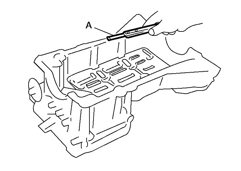
-
Also remove the old sealant from mating surface of the cylinder block.
-
Remove the old sealant from the bolt holes and threads.
CAUTION:
Do not scratch or damage the mating surfaces when cleaning off the old sealant.
Remove engine mounting bracket (RH). Refer to Exploded View.
Disconnect the harness connectors from electric intake valve timing control actuator and the exhaust valve timing control solenoid valve. Refer to Exploded View.
Remove the intake valve timing control cover [bank 1 (A)] and intake valve timing control cover [bank 2 (B)].
-
Loosen the intake valve timing control cover [bank 1 (A)] and intake valve timing control cover [bank 2 (B)] bolts in the reverse order as shown.
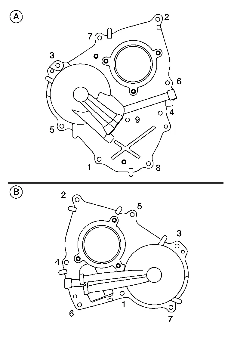
CAUTION:
The shaft in the intake valve timing control cover is inserted into the center hole of the intake camshaft sprocket. Remove the intake valve timing control cover by pulling straight out until the intake valve timing control cover disengages from the camshaft sprocket.
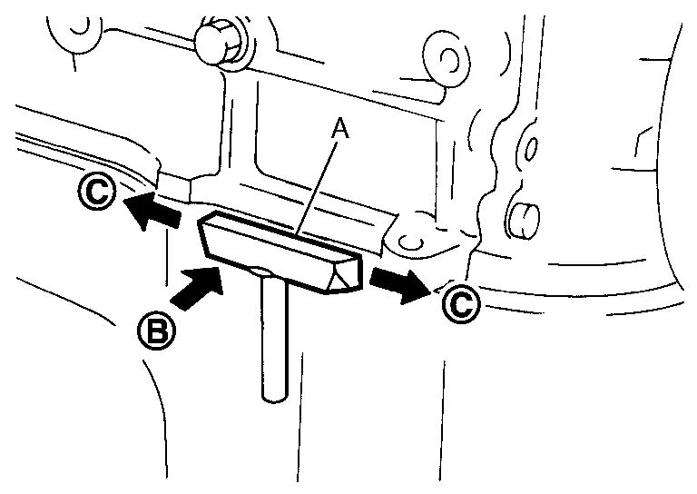
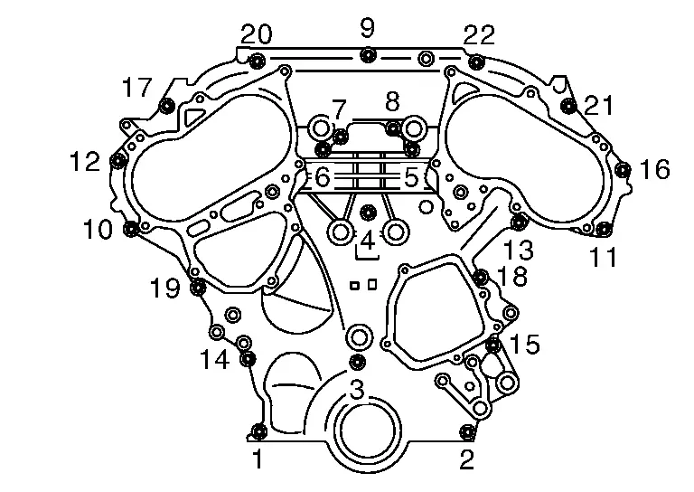
Loosen the front timing chain case bolts in reverse of the sequence shown and remove bolts.
Insert the appropriate size suitable tool into the notch (A) at the top of the front timing chain case as shown.
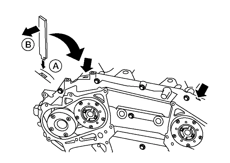
-
Cut liquid gasket for removal using Tool.
CAUTION:
-
Do not use a screwdriver or similar tool.
-
After removal, handle carefully so it does not bend or warp under a load.
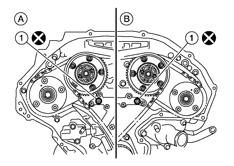
Remove O-rings (1) from rear timing chain case.

CAUTION:
Do not reuse O-rings.
| (A) | : Bank 1 |
| (B) | : Bank 2 |
Remove the front oil seal from the front timing chain case using a suitable tool.
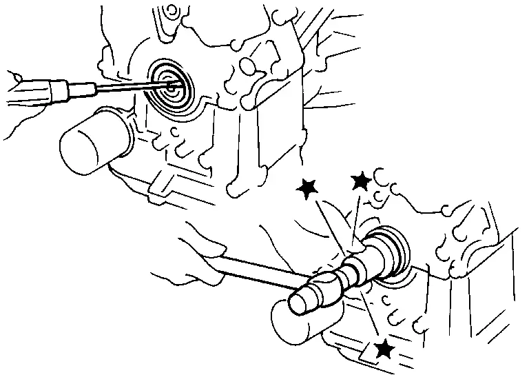
CAUTION:
Do not damage the front cover.
Remove all old liquid gasket (A) from all the bolt holes (B) and bolts.
CAUTION:
Do not damage the threads or mating surfaces.
Use a suitable tool to remove all of the old liquid gasket from the front timing chain case and opposite mating surfaces.
CAUTION:
Do not damage the mating surfaces.
Remove front timing chain case oil filters (if necessary).
Install front timing chain case oil filter (2) (if necessary).
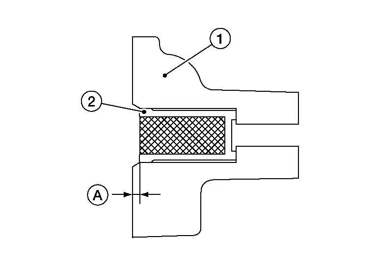
CAUTION:
-
Insert front timing chain case oil filter (2) into the front timing chain case (1) to specified distance (A).
-
Ensure oil filter mesh remains intact during insertion into the front timing chain case (1).
-
Ensure oil filter mesh does not protrude from front timing chain case (1).
| (A) | : 1.0 - 1.5 mm (0.039 - 0.059 in) |
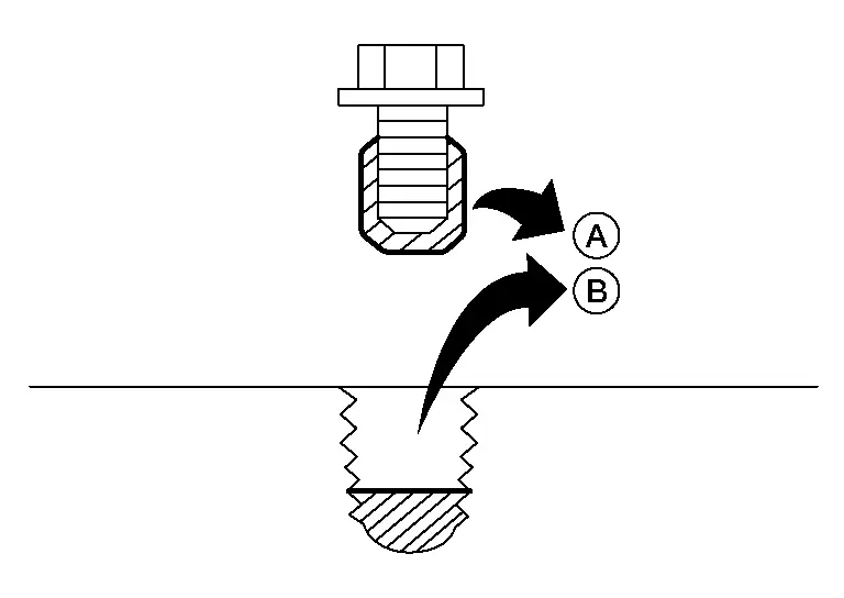
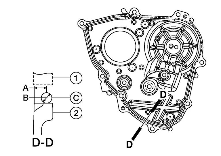
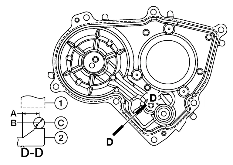
Install the new front oil seal on the front timing chain case. Apply new engine oil to the oil seal edges.
CAUTION:
Do not reuse the front oil seal.
 NOTE:
NOTE:
Install it so that each seal lip is oriented as shown.
| (A) | : Engine inside |
| (B) | : Oil seal lip |
| (C) | : Dust seal lip |
| (D) | : Engine outside |
CAUTION:
Press fit straight and avoid causing burrs or tilting the oil seal.
 NOTE:
NOTE:
-
Make sure the garter spring is in position and seal lip is not inverted.
-
Front oil seal should sit 0.0 - 0.5 mm (0.0 - 0.020 mm) from front face of front cover.
Install new O-rings (1) on rear timing chain case.
CAUTION:
Do not reuse O-rings.
| (A) | : Bank 1 |
| (B) | : Bank 2 |
Apply liquid gasket to front timing chain case as shown.
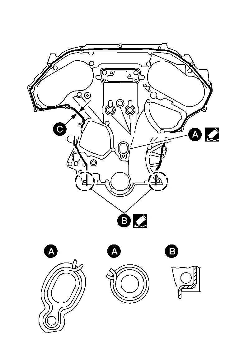
-
Use Genuine Silicone RTV Sealant or equivalent. Refer to Recommended Chemical Products and Sealants.
-
Before installation, wipe off the protruding liquid gasket.
-
(C): 2.6 - 3.6 mm (0.102 - 0.142 in) diameter.
CAUTION:
-
Installation should be done within 5 minutes after applying liquid gasket.
-
Do not fill the engine with engine oil for at least 30 minutes after the components are installed to allow the liquid gasket to cure.
Install the front timing chain case by aligning the dowel pin on the rear timing chain case with the dowel pin hole in front timing chain case.
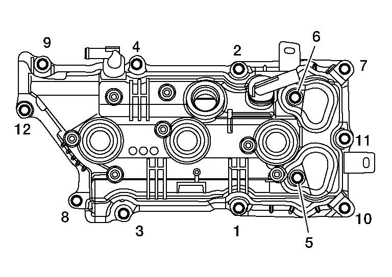
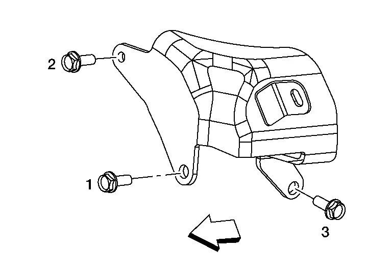
Loosely install the front timing chain case bolts.

| Bolt position | Bolt diameter |
| 1, 2 | : 8 mm (0.31 in) |
| 3 – 22 | : 6 mm (0.24 in) |
Tighten the front timing chain case bolts to the specified torque in the sequence shown.
-
Retighten the front timing chain case bolts to the specified torque in the sequence shown
| Bolt position | Tightening specification |
| 1, 2 | : 28.4 N·m (2.9 kg-m, 21 ft-lb) |
| 3 – 22 | : 12.7 N·m (1.3 kg-m, 9 ft-lb) |
Install intake valve timing control cover (bank 1) and intake valve timing control cover (bank 2) using the following procedure:Install the O-rings to the front timing chain case.
CAUTION:
Do not reuse O-ring.
Install the O-rings (1) to the valve timing control cover (bank 1).CAUTION:
Do not reuse O-rings.
 NOTE:
NOTE:
-
Lubricate O-rings with clean engine oil before installing valve timing control cover (bank 1).
-
Verify O-rings are installed into grooves in valve timing control cover correctly.
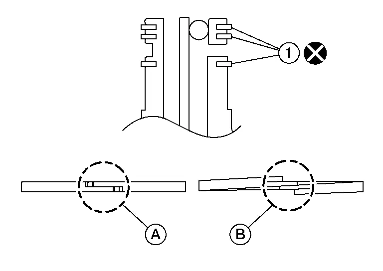
(A) : OK (B) : NG
CAUTION:
-
The components must be installed within 5 minutes of the liquid gasket application.
-
Do not re-tighten bolts after the 5 minutes have elapsed.
-
Then allow 30 minutes for the liquid gasket to set before adding oil to the engine.
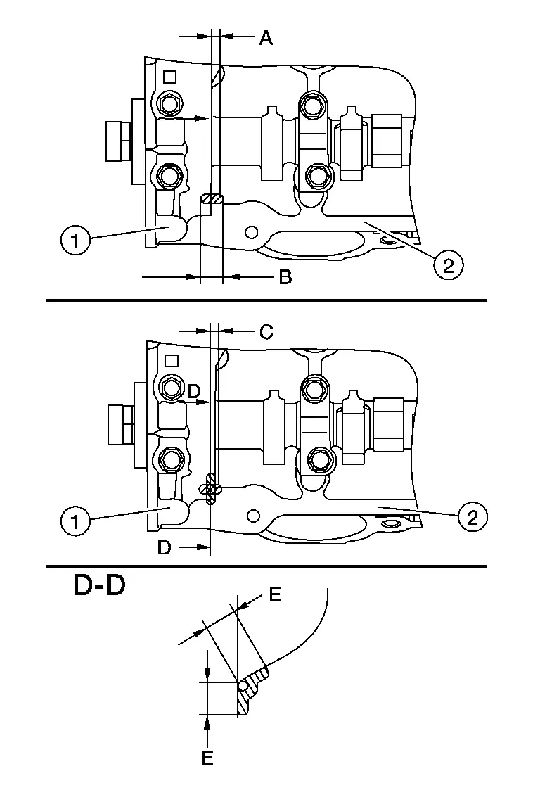
Use Genuine Silicone RTV Sealant or equivalent. Refer to Recommended Chemical Products and Sealants.
| (1) | : Front timing chain case |
| (A) | : 4.0 - 5.6 mm (0.157 - 0.220 in) |
| (B) | : 3.4 - 4.4 mm (0.134 - 0.173 in) |
CAUTION:
-
The components must be installed within 5 minutes of the liquid gasket application.
-
Do not re-tighten bolts after the 5 minutes have elapsed.
-
Then allow 30 minutes for the liquid gasket to set before adding oil to the engine.
Use Genuine Silicone RTV Sealant or equivalent. Refer to Recommended Chemical Products and Sealants.
| (1) | : Front timing chain case |
| (A) | : 4.0 - 5.6 mm (0.157 - 0.220 in) |
| (B) | : 3.4 - 4.4 mm (0.134 - 0.173 in) |

| Bolts | : 11.3 N·m (1.2 kg-m, 8 ft-lb) |
| (B) | : Bank 2 |
Install and tighten the electric intake valve timing control actuator to the specified torque.
| Electric intake valve timing control actuator bolts | : 9 N·m (0.9 kg-m, 80 in-lb) |
Apply sealant (A) to the front cover gasket and the rear oil seal retainer gasket as shown.
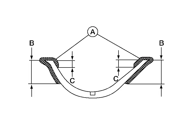
Use Genuine RTV Silicone Sealant or equivalent. Refer to Recommended Chemical Products and Sealants.
CAUTION:
-
Do not reuse front cover gasket or rear oil seal retainer gasket.
-
Installation should be done within 5 minutes after applying liquid gasket.
-
Do not fill the engine with engine oil for at least 30 minutes after the components are installed to allow the sealant to cure.
| Dimension (B) | : 15 mm (0.59 in) |
| Dimension (C) | : 5 mm (0.20 in) |
Install the front cover gasket (1) and rear oil seal retainer gasket (2) as shown.
CAUTION:
Do not reuse front cover gasket or rear oil seal retainer gasket.
 |
: Engine front |
Apply a bead of sealant to the cylinder block mating surface of the oil pan (upper) as shown.
Use Genuine RTV Silicone Sealant, or equivalent. Refer to Recommended Chemical Products and Sealants.
CAUTION:
-
Installation should be done within 5 minutes after applying liquid gasket.
-
Do not fill the engine with engine oil for at least 30 minutes after the components are installed to allow the sealant to cure.
 |
: Engine front |
Install new O-ring (1) into the cylinder block before installing oil pan (upper).
CAUTION:
Do not reuse O-ring.
| (2) | : Crankshaft pulley |
Install the oil pan (upper).

-
Tighten bolts (1) and (2) to specification within five minutes of applying the liquid gasket.
-
Tighten the remaining oil pan (upper) bolts to specification in the sequence shown.
CAUTION:
-
Installation should be done within 5 minutes after applying liquid gasket.
-
Do not fill the engine with engine oil for at least 30 minutes after the components are installed to allow the sealant to cure.
| Oil pan (upper) bolts | : 22.0 N·m (2.2 kg-m, 16 ft-lb) |
Install the oil pump and new O-rings (1) and tighten oil pump bolts (A) to the specified torque in the sequence shown (if removed).

CAUTION:
Do not reuse O-rings.
| Oil pump bolts | : 22.0 N·m (2.2 kg-m, 16 ft-lb) |
Apply a continuous bead of sealant to the oil pan (lower).
-
Be sure the sealant is 4.5 - 5.5 mm (0.177 - 0.217 in) wide.
-
Use Genuine Silicone RTV Sealant, or equivalent. Refer to Recommended Chemical Products and Sealants.
CAUTION:
-
Installation should be done within 5 minutes after applying liquid gasket.
-
Do not fill the engine with engine oil for at least 30 minutes after the components are installed to allow the sealant to cure.
| (A) | : Groove |
| (B) | : Bolt hole |
 |
: Inside |
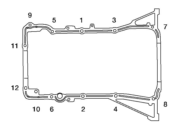
Install the oil pan (lower) and tighten the oil pan (lower) bolts to the specified torque in the sequence shown.

CAUTION:
-
Installation should be done within 5 minutes after applying liquid gasket.
-
Do not fill the engine with engine oil for at least 30 minutes after the components are installed to allow the sealant to cure.
| Oil pan (lower) bolts | : 8.8 N·m (0.90 kg-m, 78 in-lb) |
Install crankshaft pulley and tighten the bolt using the following procedure:
-
Lubricate thread and seat surface of the bolt with new engine oil.
-
Secure the crankshaft pulley using a suitable tool.
-
For the second step, angle tighten using Tool.
CAUTION:
-
Do not damage the front oil seal when inserting crankshaft pulley.
-
Use only brass or plastic hammer if tapping on the crankshaft pulley.
-
Do not hammer on pulley grooves.
| Step 1 | : 90 N·m (9.2 kg-m, 66 ft-lb) |
| Step 2 | : 90° - 96° clockwise |
| Tool number | : KV10112100 (BT-8653-A) |
Install components removed to obtain compression TDC of No.1 cylinder using the following procedure:Install rocker cover (bank 1) using the following procedure:
CAUTION:
Do not reuse rocker cover (bank 1) gasket.
-
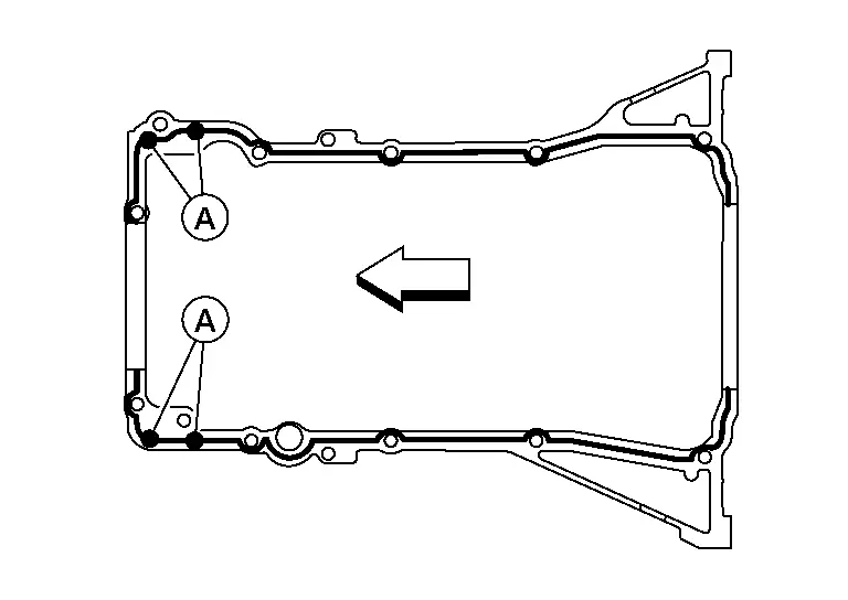
Apply a 3 mm (0.12 mm) bead of sealant to the areas on the front corners using a suitable tool.

Use Genuine Silicone RTV Sealant or equivalent. Refer to Recommended Chemical Products and Sealants.
CAUTION:
-
Installation should be done within 5 minutes after applying liquid gasket.
-
Do not fill the engine with engine oil for at least 30 minutes after the components are installed to allow the sealant to cure.
(1) : Camshaft bracket (2) : Cylinder head (A) : 4 mm (0.16 in) (B) : 5 mm (0.20 in) (C) : 4 mm (0.16 in) (E) : 10 mm (0.39 in) -
-
Tighten the rocker cover bolts to the specified torque in the sequence shown.

Rocker cover bolts Step 1 : 1.96 N·m (0.20 kg-m, 17 in-lb) Step 2 : 8.33 N·m (0.85 kg-m, 74 in-lb) 
: Engine front
CAUTION:
Do not reuse rocker cover (bank 2) gasket.
-
Apply a 3 mm (0.12 mm) bead of sealant to the areas on the front corners using a suitable tool.
Use Genuine Silicone RTV Sealant or equivalent. Refer to Recommended Chemical Products and Sealants.
CAUTION:
-
Installation should be done within 5 minutes after applying liquid gasket.
-
Do not fill the engine with engine oil for at least 30 minutes after the components are installed to allow the sealant to cure.
(1) : Camshaft bracket (2) : Cylinder head (A) : 4 mm (0.16 in) (B) : 5 mm (0.20 in) (C) : 4 mm (0.16 in) (E) : 10 mm (0.39 in) -
-
Tighten the rocker cover bolts to the specified torque in the sequence shown.
Rocker cover bolts Step 1 : 1.96 N·m (0.20 kg-m, 17 in-lb) Step 2 : 8.33 N·m (0.85 kg-m, 74 in-lb)
CAUTION:
-
Do not reuse O-ring.
-
Handle O-ring with bare hands. Do not wear gloves.
-
Lubricate O-ring with new engine oil.
-
Check that O-ring and its mating part are free of foreign material.
-
When installing O-ring, be careful not to scratch it with suitable tool or fingernails. Also be careful not to twist or stretch O-ring. If O-ring was stretched while it was being attached, do not insert it immediately into front cover.
-
Insert new O-ring straight into high pressure fuel pump. Do not decenter or twist it.
CAUTION:
-
Do not reuse O-ring.
-
Do not disassemble plunger on bottom of high pressure fuel pump.
 NOTE:
NOTE:
Apply clean engine oil to lifter contact surface and O-ring.
-
Tighten bolts one revolution while alternating sides until high pressure fuel pump is mated to No. 1 camshaft bracket.
-
Tighten bolts to the specified torque.
High pressure fuel pump bolts : 26.5 N·m (2.7 kg-m, 20 ft-lb)
CAUTION:
-
Do not reuse high pressure fuel tube (pump side).
-
Do not apply engine oil to threads of high pressure fuel pump, fuel rail (bank 1) or high pressure fuel tube (pump side).
-
Do not use high pressure fuel tube (pump side) if its terminal tip is damaged.
-
Check that there is no foreign material on the high pressure fuel tube (pump side) flare nipple or flare nuts.
-
If scratches or damage are visible on flare nipple of high pressure fuel tube, do not use it.
-
If flare nut is difficult to tighten, inspect threads for damage and replace if damage is present.
-
Install high pressure fuel tube [pump side (2)] and hand tighten flare nut (A) and flare nut (C) until contact seat.
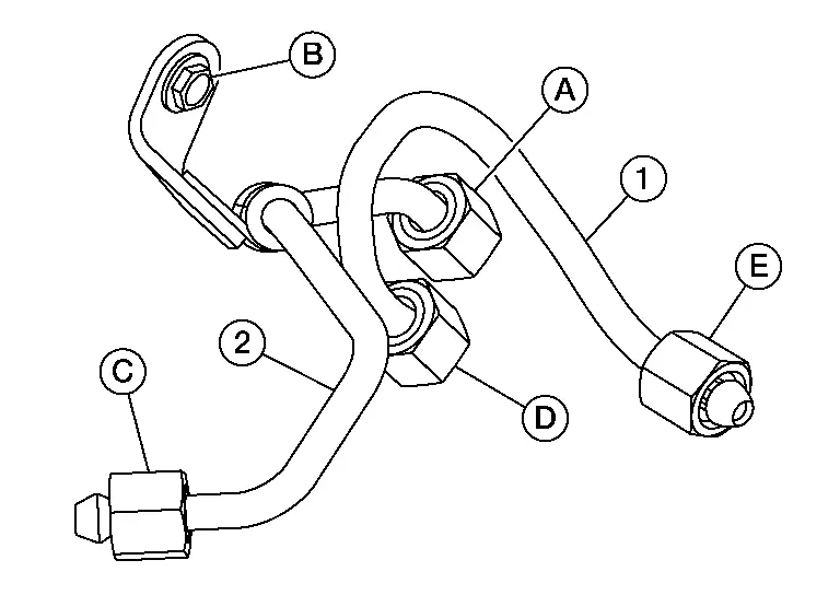
CAUTION:
When hand tightening the flare nuts, insert them so that they are aligned with the center of the pipe.
 NOTE:
NOTE:
Should be no gap between high pressure fuel tube, high pressure fuel tube bracket and rear timing chain case.
(1) : High pressure fuel tube (bank side) (D) : High pressure fuel tube (bank side) flare nut (E) : High pressure fuel tube (bank side) flare nut -
Hand tighten bolt (B).
-
Tighten flare nut (C) and then flare nut (A) to the specified torque.
Flare nut : 15 N·m (1.5 kg-m, 11 ft-lb) -
Tighten flare nut (C) and then flare nut (A) to the specified torque.
Flare nut : 23.0 N·m (2.3 kg-m, 17 ft-lb) -
Tighten bolt (B) to the specified torque.
Bolt : 13.5 N·m (1.4 kg-m, 10 ft-lb)
| (A) | : Clip |
 NOTE:
NOTE:
High pressure fuel pump insulator should be free from distortion when installed.
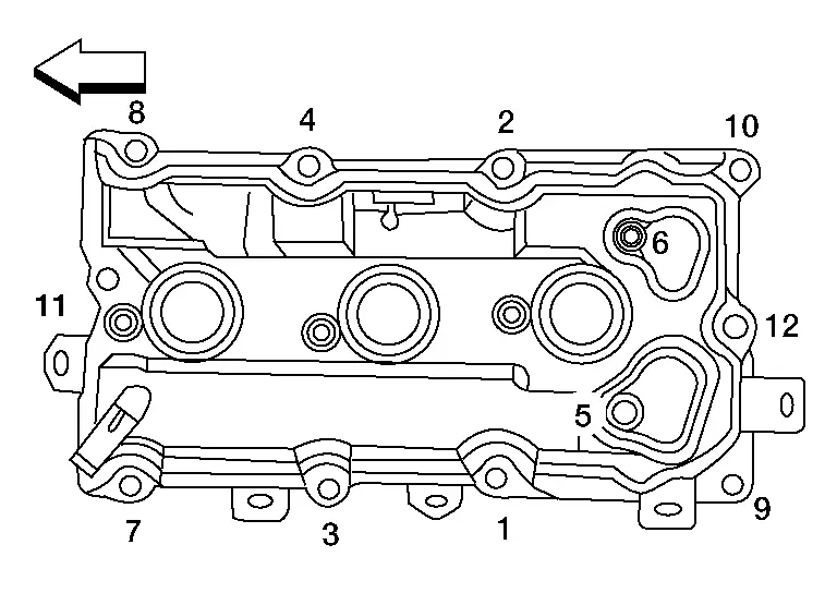
Tighten high pressure fuel pump cover bolts to the specified torque in the sequence shown.
| High pressure fuel pump cover bolts | : 11.0 N·m (1.1 kg-m, 8 ft-lb) |
 |
: Engine front |

CAUTION:
Do not reuse intake manifold gaskets.
| Step 1 | : 7.4 N·m (0.75 kg-m, 65 in-lb) |
| Step 2 | : 25.5 N·m (2.6 kg-m, 19 ft-lb) |
 |
: Engine front |
CAUTION:
Do not reuse intake manifold collector gasket.
| Intake manifold collector nuts and bolts | : 11.0 N·m (1.1 kg-m, 8 ft-lb) |
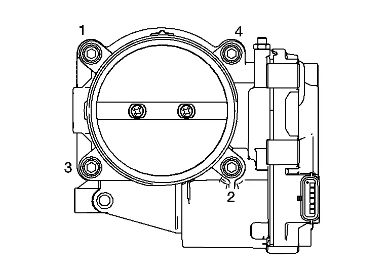
CAUTION:
Do not reuse electric throttle control actuator gasket.
Rotate crankshaft pulley in normal direction (clockwise when viewed from front) to confirm it turns smoothly.
Installation of the remaining components is in the reverse order of removal.
CAUTION:
Perform ELECTRIC IVT CONTROL ACTUATOR POSITION LEARNING. Refer to Description.
 NOTE:
NOTE:
After installation, perform the following:
-
Perform the ″Throttle Valve Closed Position Learning″ when harness connector of the electric throttle control actuator is disconnected. Refer to Description.
-
Perform the ″Idle Air Volume Learning″ when the electric throttle control actuator is replaced. Refer to Description.
INSPECTION AFTER INSTALLATION
-
Before starting engine, check oil/fluid levels including engine coolant and engine oil. If less than required quantity, fill to the specified level. Refer to Fluids and Lubricants (FOR USA AND CANADA) or Fluids and Lubricants (FOR MEXICO).
-
Use procedure below to check for fuel leakage.
-
Place ignition switch in the "ON" position (with engine stopped). With fuel pressure applied to fuel piping, check for fuel leakage at connection points.
-
Start engine. With engine speed increased, check again for fuel leakage at connection points.
-
Run engine to check for unusual noise and vibration.
 NOTE:
NOTE:
If hydraulic pressure inside timing chain tensioner drops after removal and installation, slack in the guide may generate a pounding noise during and just after engine start. However, this is normal. Noise will stop after hydraulic pressure rises.
-
Warm up engine thoroughly to make sure there is no leakage of fuel, exhaust gas, or any oils/fluids including engine oil and engine coolant.
-
Bleed air from passages in lines and hoses, such as in cooling system.
-
After cooling down engine, again check oil/fluid levels including engine oil and engine coolant. Refill to specified level, if necessary.
-
Summary of the inspection items:
Item Before starting engine Engine running After engine stopped Engine coolant Level Leakage Level Engine oil Level Leakage Level Transmission/transaxle fluid A/T and CVT Models Leakage Level/Leakage Leakage M/T Models Level/Leakage Leakage Level/Leakage Other oils and fluids* Level Leakage Level Fuel Leakage Leakage Leakage Exhaust gas — Leakage — *Power steering fluid, brake fluid, etc.

Nissan Pathfinder (R53) 2022-2026 Service Manual
Contact Us
Nissan Pathfinder Info Center
Email: info@nipathfinder.com
Phone: +1 (800) 123-4567
Address: 123 Pathfinder Blvd, Nashville, TN 37214, USA
Working Hours: Mon–Fri, 9:00 AM – 5:00 PM (EST)
