Nissan Pathfinder: Removal and Installation - Timing Chain ++
Exploded View
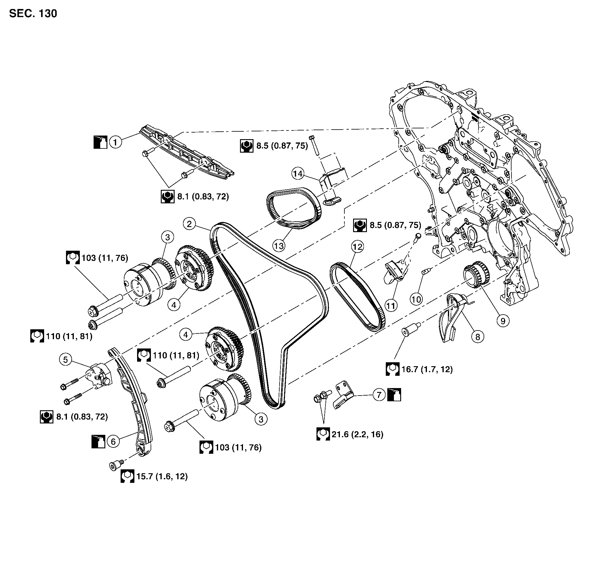
| 1. | Internal chain guide | 2. | Timing chain (primary) | 3. | Camshaft sprocket (EXH) |
| 4. | Camshaft sprocket (INT) | 5. | Timing chain tensioner (primary) | 6. | Slack guide |
| 7. | Tension guide | 8. | Oil pump drive chain tensioner | 9. | Crankshaft sprocket |
| 10. | Timing chain oil jet | 11. | Timing chain tensioner [secondary (bank 2)] | 12. | Timing chain [secondary (bank 2)] |
| 13. | Timing chain [secondary (bank 1)] | 14. | Timing chain tensioner [secondary (bank 1)] |
Removal and Installation
CAUTION:
-
After removing timing chains, do not turn the crankshaft and camshaft separately or the valves will strike the pistons.
-
When installing camshafts, chain tensioners, oil seals, or other sliding parts, lubricate contacting surfaces with new engine oil.
-
Apply new engine oil to bolt threads and seat surfaces when installing camshaft sprockets, camshaft brackets, and crankshaft pulley.
REMOVAL
Remove front timing chain case. Refer to Removal and Installation.
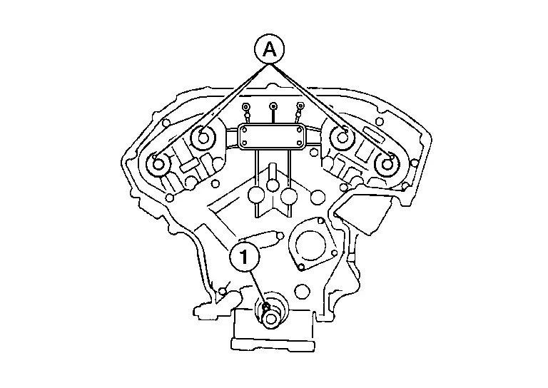
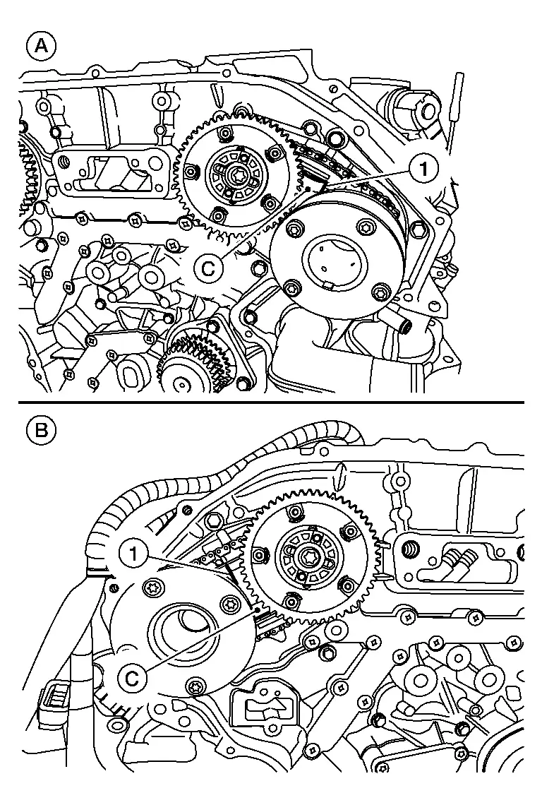
Remove the timing chain tensioner [primary (1)].Pull lever (C) down and release plunger (D) stopper tab (A). Plunger stopper tab can be pushed up to release (coaxial structure with lever).
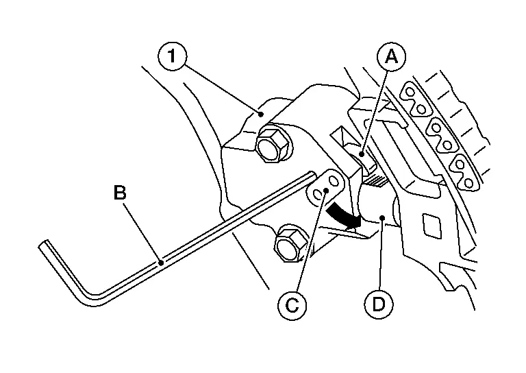
| (B) | : Suitable tool |
Remove internal chain guide (1), tension guide (3) and slack guide(2).
 NOTE:
NOTE:
Tension guide can be removed after removing timing chain (primary).
Remove timing chain (primary) and crankshaft sprocket.
CAUTION:
After removing timing chains, do not turn the crankshaft and camshaft separately or the valves will strike the pistons.
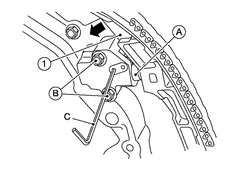
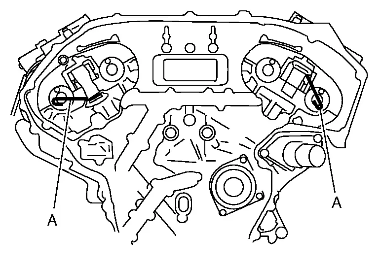
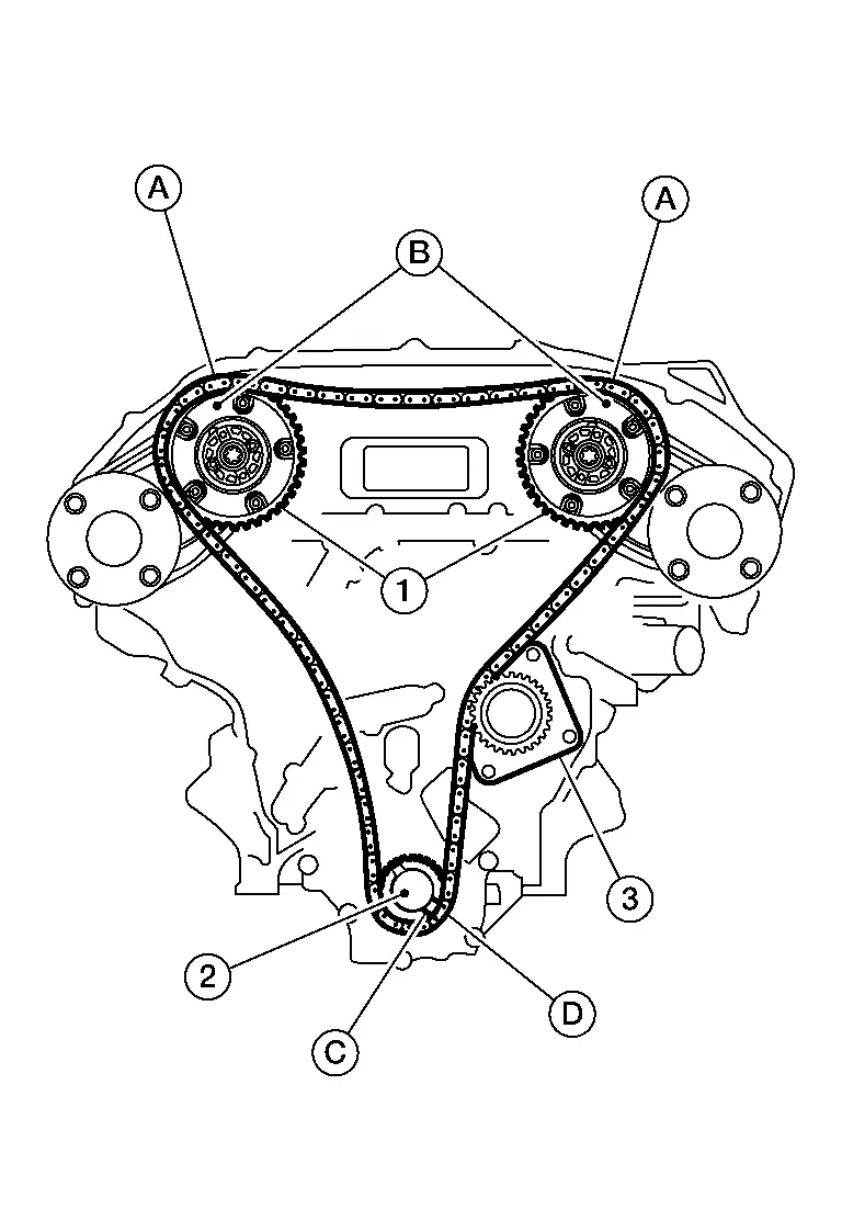
Remove timing chain (secondary) and camshaft sprockets as follows:Insert a suitable stopper pin into the hole (C) on the bank 2 (A) and bank 1 (B) timing chain tensioners [secondary (1)].

 NOTE:
NOTE:
-
Use approximately 0.5 mm (0.02 in) diameter hard metal pin as a stopper pin.
-
Removal of camshaft bracket (No. 1) is required prior to removing the timing chain tensioner (secondary).
-
Secure the hexagonal portion of camshaft using a suitable tool to loosen bolts.
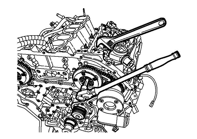
CAUTION:
Do not loosen bolts using anything other than the camshaft hexagonal portion. Do not apply tension to the timing chain.
-
Turn camshaft slightly to keep the chain tight when removing the timing chain (secondary).
-
Insert 0.5 mm (0.020 in) thick metal or resin plate (C) between timing chain and timing chain tensioner plunger [guide (B)]. Remove timing chain (secondary) (2) together with camshaft sprockets with timing chain loose from guide groove.
CAUTION:
Be careful of plunger coming off when removing timing chain (secondary). The plunger of timing chain tensioner (secondary) moves during operation, which could cause the stopper pin to fall out.
(1) : Timing chain tensioner (secondary) (A) : Stopper pin
CAUTION:
-
Handle camshaft sprocket (INT) carefully to avoid any shock to camshaft sprocket.
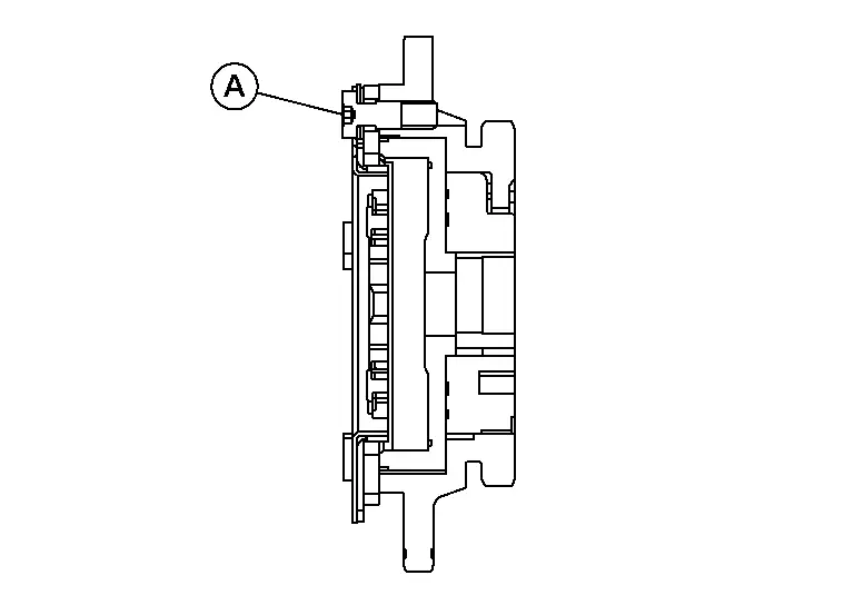
-
Do not disassemble. [Do not loosen bolts (A) as shown].
Remove oil pump drive chain and crankshaft sprocket.
Remove bolt and remove oil pump drive chain tensioner.
INSPECTION
Check for cracks and any excessive wear of the timing chain. Replace the timing chain as necessary.
INSTALLATION
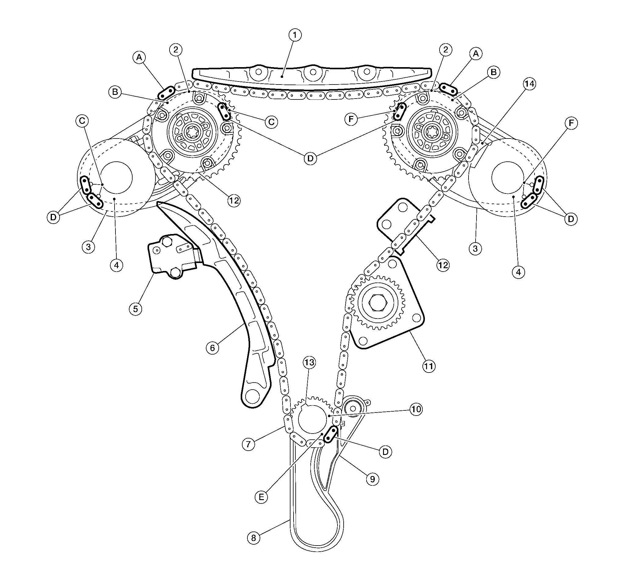
| 1. | Internal chain guide | 2. | Camshaft sprocket (INT) | 3. | Timing chain (secondary) |
| 4. | Camshaft sprocket (EXH) | 5. | Timing chain tensioner (primary) | 6. | Slack guide |
| 7. | Timing chain (primary) | 8. | Oil pump drive chain | 9. | Oil pump drive chain tensioner |
| 10. | Crankshaft sprocket | 11. | Water pump | 12. | Tension guide |
| 13. | Crankshaft key | 14. | Timing chain tensioner (secondary) | A. | Mating mark (blue link) |
| B. | Mating mark | C. | Mating mark (circle) | D. | Mating mark (pink link) |
| E. | Mating mark | F. | Mating mark (oblong) |
 NOTE:
NOTE:
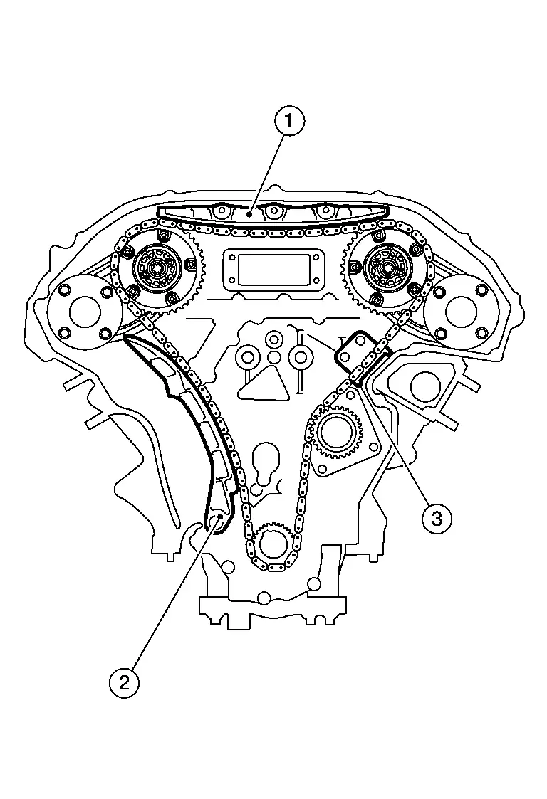
-
This illustration shows the relationship between the mating mark on each timing chain and on the corresponding sprocket with the components installed.
-
The mating mark (circle) and mating mark (oblong) for the timing chain (secondary) are located on the rear of the camshaft sprocket (INT) and camshaft sprocket (EXH).
Check that dowel pin (A) and crankshaft key (1) are located as shown. (No. 1 cylinder at compression TDC)
 NOTE:
NOTE:
Camshaft may not remain in exact position because pressure on camshaft lobes from valve springs may cause camshaft to rotate slightly. It is acceptable as long as camshaft dowel pins are placed in the same direction.
| Camshaft dowel pin | |
| : At cylinder head upper face side in each bank | |
| Crankshaft key | |
| : At cylinder head side of bank 1 | |
Install timing chain (secondary) and camshaft sprockets (INT and EXH) as follows:
CAUTION:
Mating marks between timing chain and sprockets slip easily. Confirm all mating mark positions repeatedly during the installation process.
Push plunger of timing chain tensioner (secondary) and keep it pressed in with suitable tool(A).
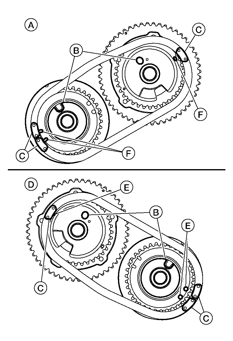
| (A) | : Bank 2 |
| (B) | : Dowel pin groove |
| (C) | : Pink link |
| (D) | : Bank 1 |
| (E) | : Mating mark (circle on rear face) |
| (F) | : Mating mark (oblong on rear face) |
 NOTE:
NOTE:
Bank 1 and Bank 2 shown (rear view).
-
Align the mating marks on timing chain [secondary (pink link)] with the mating marks on camshaft sprockets (INT and EXH), and install them.
-
Align dowel pin on camshafts with the groove on sprockets, and install them.
-
Tighten the bolts for the camshaft sprockets by hand enough to prevent the dowel pins from falling out of the grooves.
-
It may be difficult to visually check the dislocation of mating marks during and after installation. To make the matching easier, make a mating mark (A) on the top of sprocket teeth and its extended line with paint.
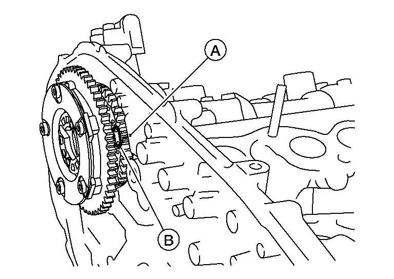
(B) : Mating mark (pink link)
After confirming the mating marks are aligned, tighten the camshaft sprocket bolts.

-
Secure the camshaft using a suitable tool at the hexagonal portion to tighten the bolts.
Remove stopper pins from timing chain tensioners [secondary (1)].
| (A) | : Bank 1 |
| (B) | : Bank 2 |
| (C) | : Stopper pin |
Install oil pump drive chain tensioner.
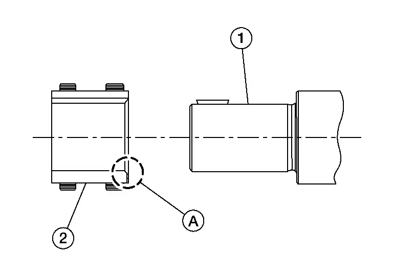
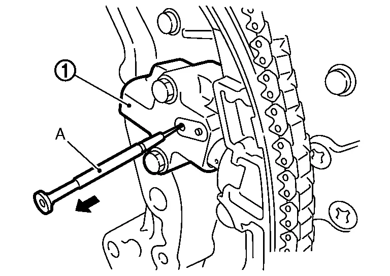
Install oil pump drive chain and oil pump drive chain sprocket onto the crankshaft (1).
 NOTE:
NOTE:
Install the chamfered side (A) of the crankshaft sprocket (2) first.
Install the timing chain (primary).
-
Install timing chain (primary) so the mating mark (B) on camshaft sprocket (1) is aligned with the blue link (A) on the timing chain, while the mating mark (C) on the crankshaft sprocket (2) is aligned with the pink link (D) on the timing chain, as shown.
-
When it is difficult to align mating marks of the timing chain (primary) with each sprocket, gradually turn the camshaft using a suitable tool on the hexagonal portion to align it with the mating marks.
-
During alignment, be careful to prevent dislocation of mating mark alignments of the secondary timing chains.
| (3) | : Water pump |
Install the internal chain guide (1), slack guide (2) and tension guide (3).

CAUTION:
Do not over tighten slack guide bolt (2). It is normal for a gap (A) to exist under the bolt seat when bolt is tightened to specification.
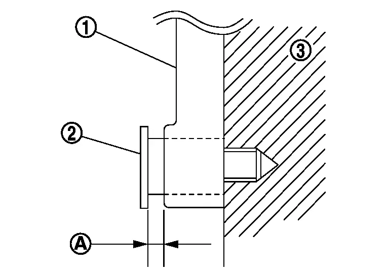
| (1) | : Slack guide |
| (3) | : Cylinder block |
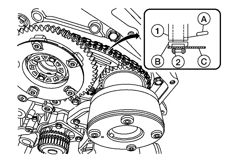
Install the timing chain tensioner (primary) with the following procedure:Pull plunger stopper tab (A) up (or turn lever downward) so as to remove plunger stopper tab from the ratchet of plunger (D).
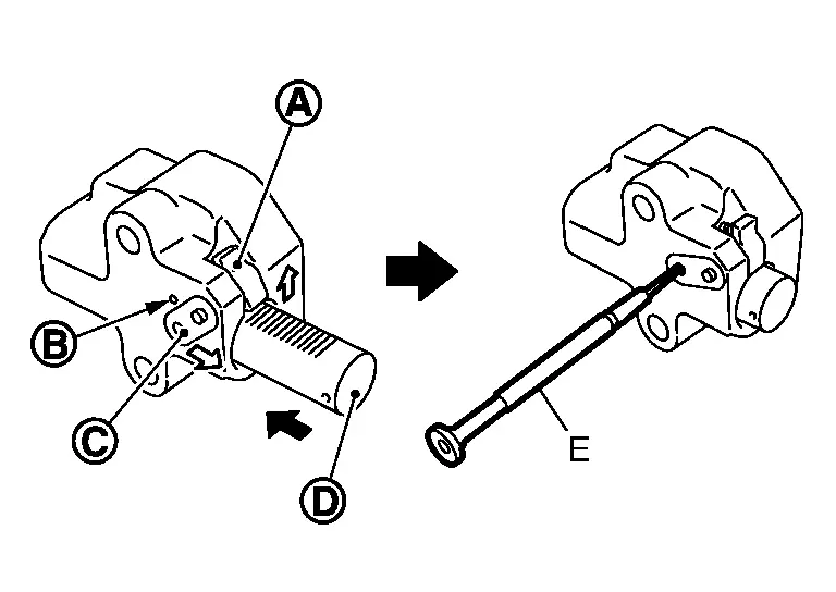
 NOTE:
NOTE:
Plunger stopper tab and lever (C) are synchronized.
Push plunger into the inside of tensioner body. Hold plunger in the fully compressed position by engaging plunger stopper tab with the tip of ratchet. To secure lever, insert stopper pin (E) through hole of lever into tensioner body hole (B).-
The lever parts and the tab are synchronized. Therefore, the plunger will be secured under this condition.
 NOTE:
NOTE:
Illustration shows the example of 1.2 mm (0.047 in) diameter thin screwdriver being used as the stopper pin.
Install timing chain tensioner (primary) (1).
-
Remove any dirt and foreign materials completely from the back and the mount surfaces of timing chain tensioner (primary).
Reconfirm that the matching marks on the sprockets and the timing chain have not slipped out of alignment.
Install the front timing chain case. Refer to Removal and Installation.
Installation of the remaining components is in the reverse order of removal.

Nissan Pathfinder (R53) 2022-2026 Service Manual
Contact Us
Nissan Pathfinder Info Center
Email: info@nipathfinder.com
Phone: +1 (800) 123-4567
Address: 123 Pathfinder Blvd, Nashville, TN 37214, USA
Working Hours: Mon–Fri, 9:00 AM – 5:00 PM (EST)
