Nissan Pathfinder: Brake System - Removal and Installation
- Brake Pedal
- Brake Piping
- Front Brake Piping
- Brake Master Cylinder
- Brake Booster
- Vacuum Lines
- Front Brake Pad
- Front Brake Caliper Assembly ➤
- Front Disc Brake Rotor
- Rear Brake Pad
- Rear Brake Caliper Assembly ➤
- Rear Disc Brake Rotor
Brake Pedal Nissan Pathfinder R53
Exploded View
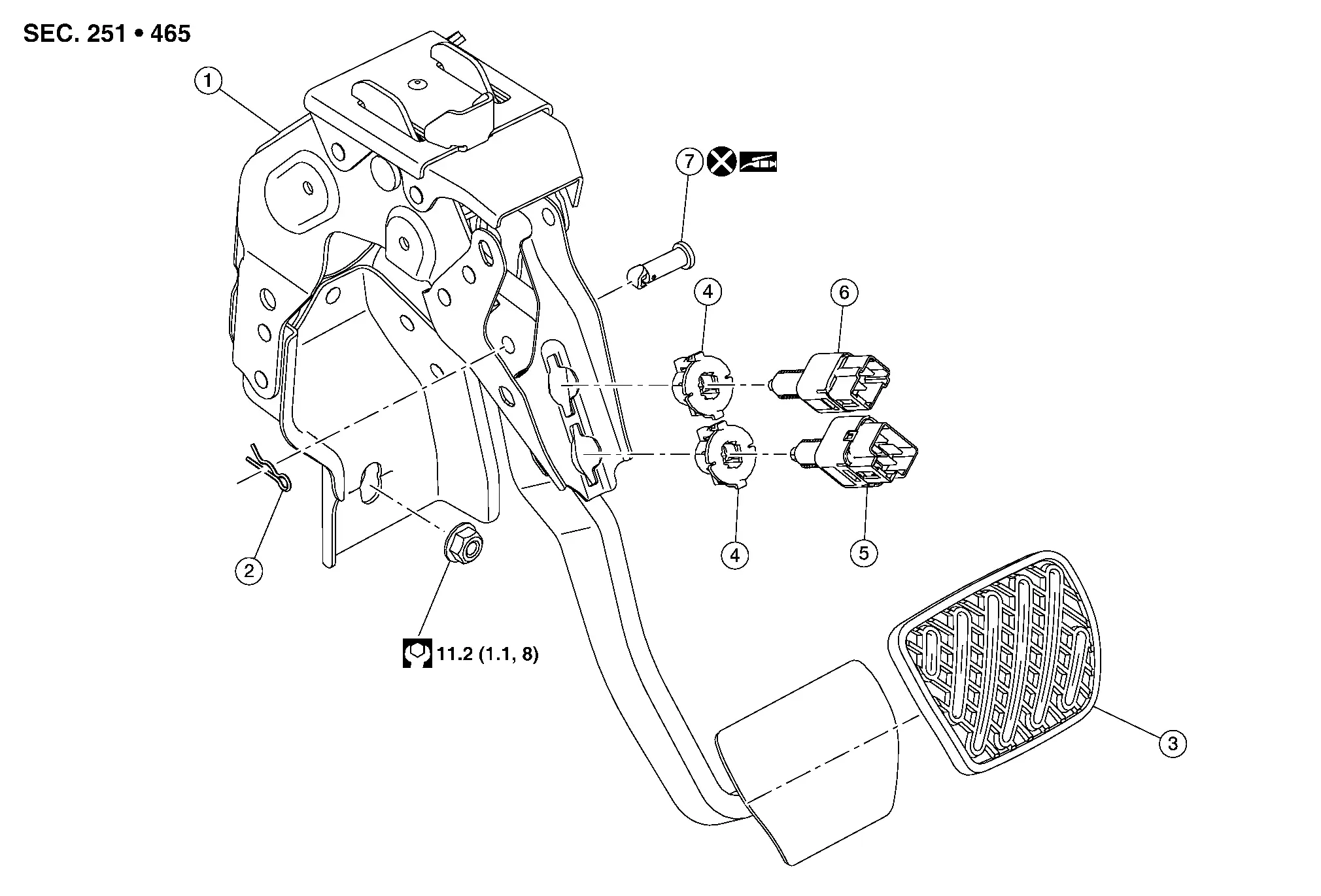
| 1. | Brake pedal assembly | 2. | Snap pin | 3. | Brake pedal pad |
| 4. | Clip | 5. | Stop lamp switch | 6. | Brake pedal position switch |
| 7. | Clevis pin |
Removal and Installation
REMOVAL
Disconnect the negative terminal from the battery. Refer to Battery Disconnect.
Remove the instrument lower panel LH. Refer to Removal and Installation.
Disconnect the harness connector from the stop lamp switch.
Disconnect the harness connector from the brake pedal position switch.
Using a suitable tool, separate the harness clips from the brake pedal assembly.
Remove the snap pin and the clevis pin from the brake pedal assembly and the brake booster input rod. Refer to Exploded View.
CAUTION:
Do not reuse the clevis pin.
Remove the nut from the bottom of the brake pedal assembly.
Remove the nuts and the brake pedal assembly from the brake booster. Refer to Exploded View.
CAUTION:
Support the brake booster and master cylinder assembly to avoid dropping or contacting other parts.
Remove the stop lamp switch, if necessary.
Remove the brake pedal position switch, if necessary.
INSPECTION AFTER REMOVAL
-
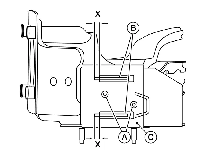
Check the following items and replace the brake pedal assembly if necessary.
-
Check the brake pedal upper rivet (made of aluminum) (A) for deformation.
-
Check the brake pedal for damage and cracks on the welded parts.
-
Check the overlap distance (X) of sub-bracket (B) and slide plate (C).
Overlap distance (X) between sub-bracket (B) and slide plate (C) : Refer to Brake Pedal.
-
INSTALLATION
Installation is in the reverse order of removal.
-
Apply multi-purpose grease to the clevis pin.
-
Inspect the brake pedal height after installing the brake pedal to the Nissan Pathfinder vehicle. Refer to Inspection.
CAUTION:
-
Replace the brake pedal if it has been dropped or sustained an impact.
-
Do not reuse the clevis pin.
Brake Piping Nissan Pathfinder Fifth generation
Hydraulic Layout
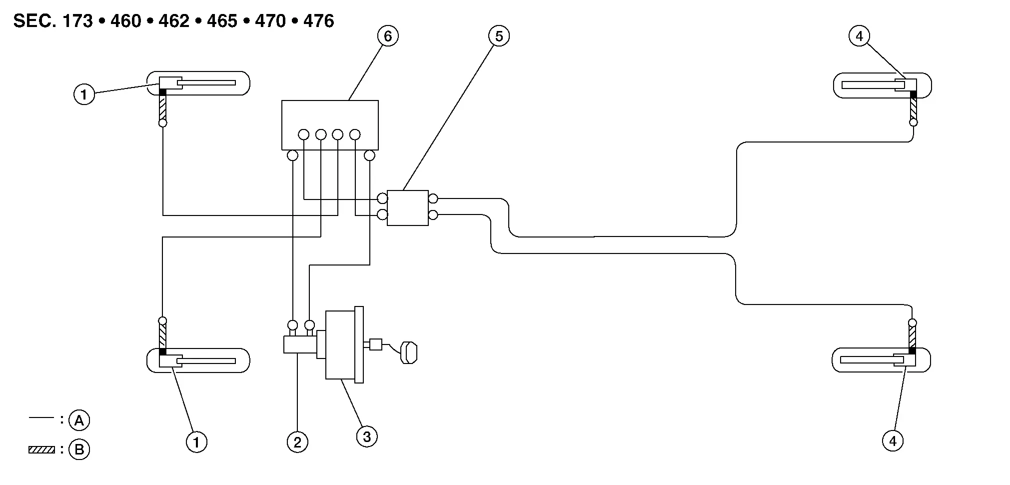
| 1. | Front disc brake | 2. | Master cylinder assembly | 3. | Brake booster |
| 4. | Rear disc brake | 5. | Connector | 6. | ABS actuator and electric unit (control unit) |
| A. | Brake tube | B. | Brake hose | ||
 : Flare nut : Flare nut |
|||||
 : Union bolt : Union bolt |
|||||
Front Brake Piping Nissan Pathfinder 2022
Exploded View
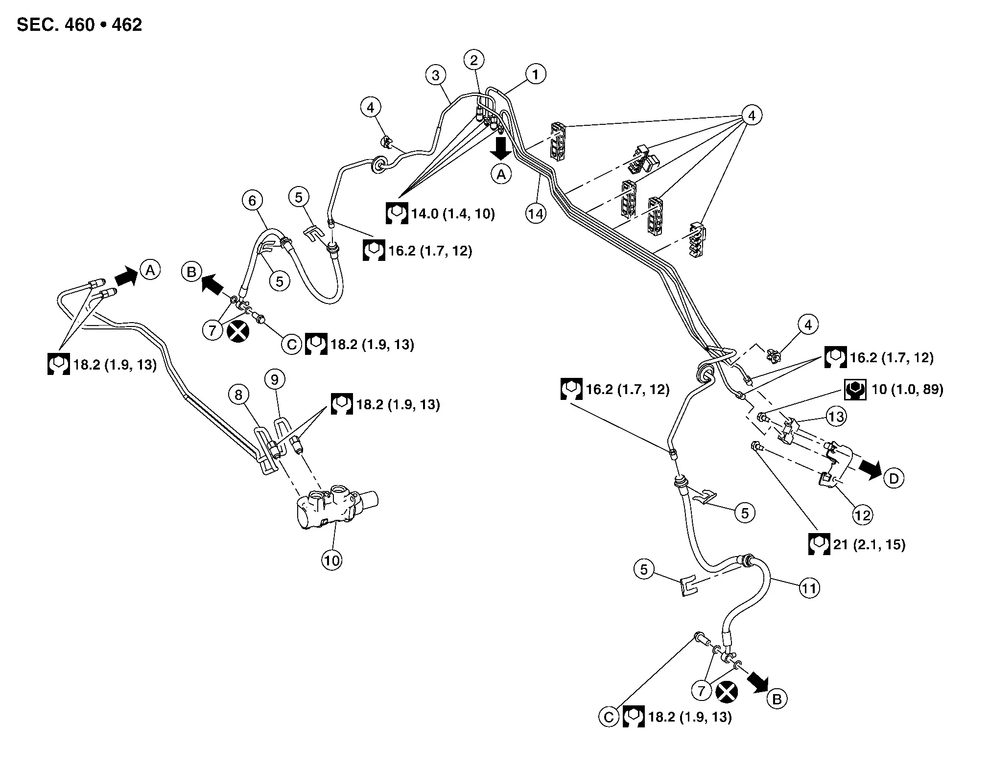
| 1. | Brake tube to front (LH) | 2. | Brake tube to connector to rear (RH) | 3. | Brake tube to front (RH) |
| 4. | Clamp | 5. | Lock plate | 6. | Brake hose (RH) |
| 7. | Copper sealing washer | 8. | Master cylinder secondary to ABS actuator brake tube | 9. | Master cylinder primary to ABS actuator brake tube |
| 10. | Master cylinder | 11. | Brake hose (LH) | 12. | Connector bracket |
| 13. | Connector | 14. | Brake tube to connector to rear (LH) | A. | To ABS actuator and electric unit (control unit). Refer to Exploded View. |
| B. | To front brake caliper assembly. Refer to Exploded View. | C. | Union bolt | D. | To rear brake tube. Refer to Exploded View. |
Removal and Installation
CAUTION:
-
All hoses and piping (tubes) must be free from excessive bending, twisting, and pulling.
-
Make sure there is no interference with other parts when turning steering both clockwise and counterclockwise.
-
Do not spill or splash brake fluid on painted surfaces. Brake fluid may seriously damage paint. Wipe it off immediately and wash with water if it gets on a painted surface.
-
Do not allow foreign matter (e.g. dust) and oils other than brake fluid to enter the reservoir tank.
 NOTE:
NOTE:
When removing components such as hoses, tubes/lines, etc., cap or plug openings to prevent fluid from spilling.
REMOVAL
Remove the reservoir tank cap. Refer to Exploded View.
Remove the front wheel and tire using power tool. Refer to Removal and Installation.
Loosen the flare nut using a flare nut wrench. Separate the brake tube from the brake hose. Refer to Exploded View.
CAUTION:
-
Do not scratch the flare nut and the brake tube.
-
All brake hoses and tubes must be free from excessive bending, twisting and pulling.
Remove the union bolt (B) and the brake hose (1) from the brake caliper (3). Remove and discard the copper sealing washers (2).

CAUTION:
Do not reuse copper sealing washers.
Remove the lock plates and remove the brake hose.
INSTALLATION
Assemble the union bolt (B) and the copper sealing washers (2) to the brake hose (1) and install it as an assembly to the brake caliper (3). Align the brake hose part (A) with the brake caliper assembly projections, and tighten the union bolt to the specified torque. Refer to Exploded View.

CAUTION:
Do not reuse copper sealing washers.
Install the brake tube to the brake hose, temporarily tighten the flare nut by hand until it does not rotate further, and attach the brake hose to the brackets with the lock plates.
CAUTION:
Check that the brake hoses and tubes are not bent or twisted.
Tighten the flare nut to the specified torque using a flare nut crowfoot and a torque wrench.
CAUTION:
Do not scratch the flare nut and the brake tube.
Refill with new brake fluid and bleed air from the brake system. Refer to Bleeding Brake System.
CAUTION:
Do not reuse drained brake fluid.
Install the front wheel and tire. Refer to Removal and Installation.
Perform the inspection after installation. Refer to Inspection.
Brake Master Cylinder Nissan Pathfinder 2022
Exploded View
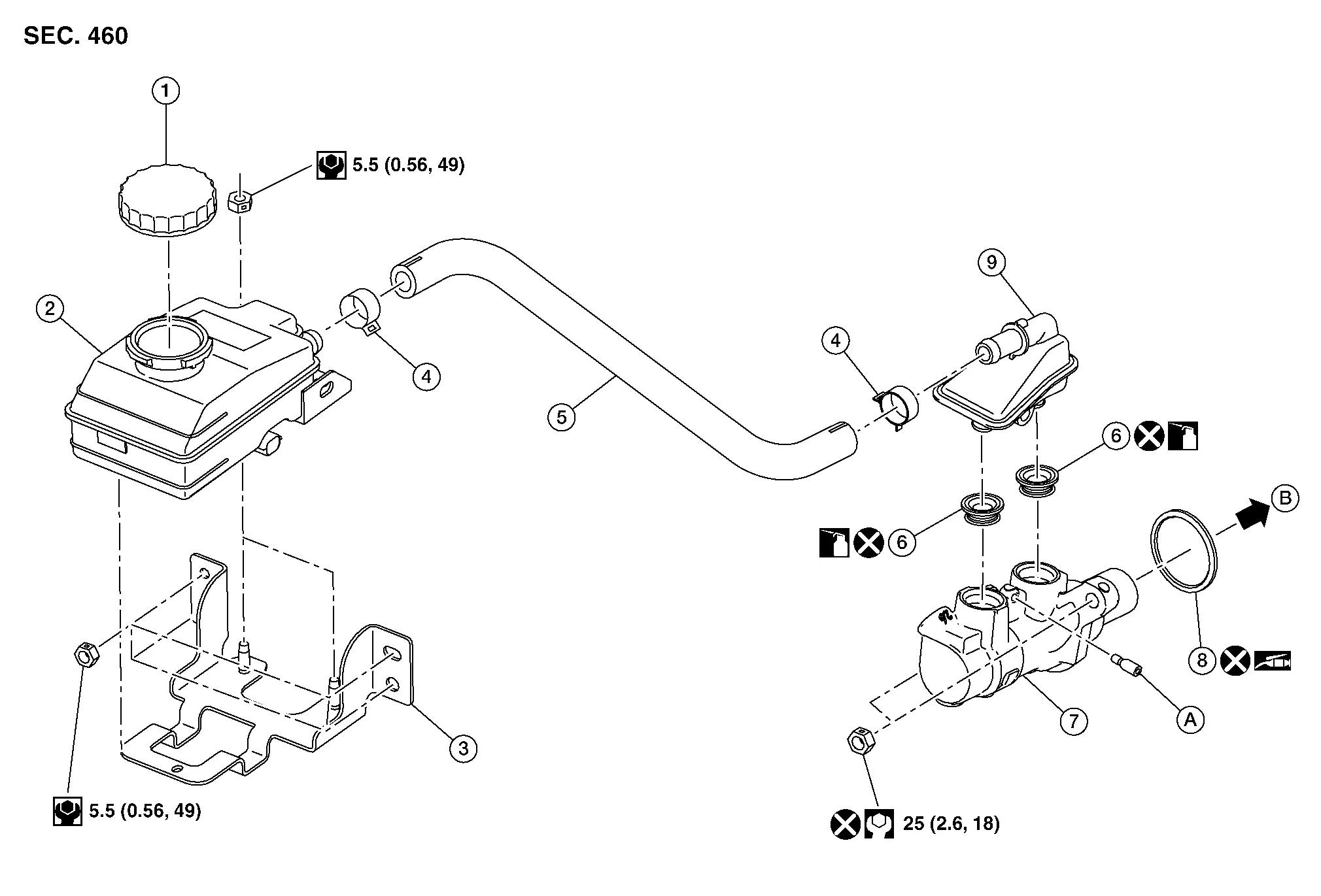
| 1. | Reservoir tank cap | 2. | Reservoir tank | 3. | Reservoir tank bracket |
| 4. | Hose clamp | 5. | Hose | 6. | Grommet |
| 7. | Master cylinder body | 8. | O-ring | 9. | Sub tank |
| A. | Screw | B. | To brake booster. Refer to Exploded View. |
 |
PBC (Poly Butyl Cuprysil) grease or silicone-based grease |
 |
Brake fluid |
Removal and Installation
CAUTION:
-
Do not spill or splash brake fluid on painted surfaces. Brake fluid may seriously damage paint. Wipe it off immediately and wash with water if it gets on a painted surface.
-
Do not reuse drained brake fluid.
 NOTE:
NOTE:
When removing components such as hoses, tubes/lines, etc., cap or plug openings to prevent fluid from spilling.
REMOVAL
Slide the connector position assurance to unlock the harness connector. Disconnect the harness connector from the brake fluid level switch.
Using a suitable tool, separate the harness clip from the reservoir tank.
Remove the nuts and separate the reservoir tank bracket from the cowl top extension. Refer to Exploded View.
Remove the air cleaner housing. Refer to Removal and Installation.
Loosen the brake tube flare nuts using a flare nut wrench. Separate the brake tubes from the master cylinder body. Refer to Exploded View.
CAUTION:
-
Do not scratch the flare nuts or the brake tubes.
-
Do not deform or bend the brake tubes.
Remove the nuts and the master cylinder assembly.
CAUTION:
-
Do not reuse the master cylinder nuts.
-
Do not depress the brake pedal after the master cylinder is removed.
-
The piston is exposed. Do not damage the piston when removing the master cylinder.
-
The piston may be damaged if separated from the master cylinder. Do not hold the piston. Hold the master cylinder body.
 NOTE:
NOTE:
The reservoir tank, the reservoir tank bracket, the brake hose, the sub tank, and the master cylinder body can be removed as the master cylinder assembly.
Remove the O-ring.
CAUTION:
Do not reuse the O-ring.
If necessary, disassemble the master cylinder assembly. Refer to Disassembly and Assembly.
INSTALLATION
Installation is in the reverse order of removal.
-
Apply PBC (Poly Butyl Cuprysil) grease or silicone grease to the O-ring.
-
Temporarily tighten the brake tube flare nut to the master cylinder by hand. Then tighten it to the specified torque using a flare nut crowfoot and a torque wrench. Refer to Exploded View.
-
After installation, bleed air from the brake system. Refer to Bleeding Brake System.
-
Perform the inspection after installation. Refer to Inspection.
CAUTION:
-
Do not reuse the master cylinder nuts.
-
Do not reuse the O-ring.
-
Make sure the brake hoses and tubes are not twisted or bent.
-
Make sure the flare nuts and the brake tubes are not scratched.
-
Make sure no dirt and dust are present on the piston before installation. Clean the piston with new brake fluid if necessary.
Disassembly and Assembly
CAUTION:
-
Do not spill or splash brake fluid on painted surfaces. Brake fluid may seriously damage paint. Wipe it off immediately and wash with water if it gets on a painted surface.
-
Do not reuse drained brake fluid.
-
Do not disassemble the master cylinder body.
-
Remove the sub tank only when necessary.
-
Do not drop removed parts. The parts must not be reused if they are dropped.
 NOTE:
NOTE:
When removing components such as hoses, tubes/lines, etc., cap or plug openings to prevent fluid from spilling.
DISASSEMBLY
Remove the master cylinder assembly. Refer to Removal and Installation.
Remove the nuts and the reservoir tank bracket from the reservoir tank. Refer to Exploded View.
Remove the reservoir tank cap.
Loosen the hose clamp and remove the reservoir tank from the hose.
Loosen the hose clamp and remove the hose from the sub tank.
Secure the master cylinder body in a vise.
CAUTION:
Always use copper plates or cloth between the vise and the master cylinder body. Do not overtighten the vise.
Remove the screw, the sub tank, and the grommets from the master cylinder body. Discard the grommets.
CAUTION:
Do not reuse the grommets.
ASSEMBLY
Assembly is in the reverse order of disassembly.
Apply new brake fluid to the grommets.
CAUTION:
-
Do not reuse the grommets.
-
Do not use mineral oil such as gasoline or light oil.
Brake Booster Nissan Pathfinder Fifth generation
Exploded View
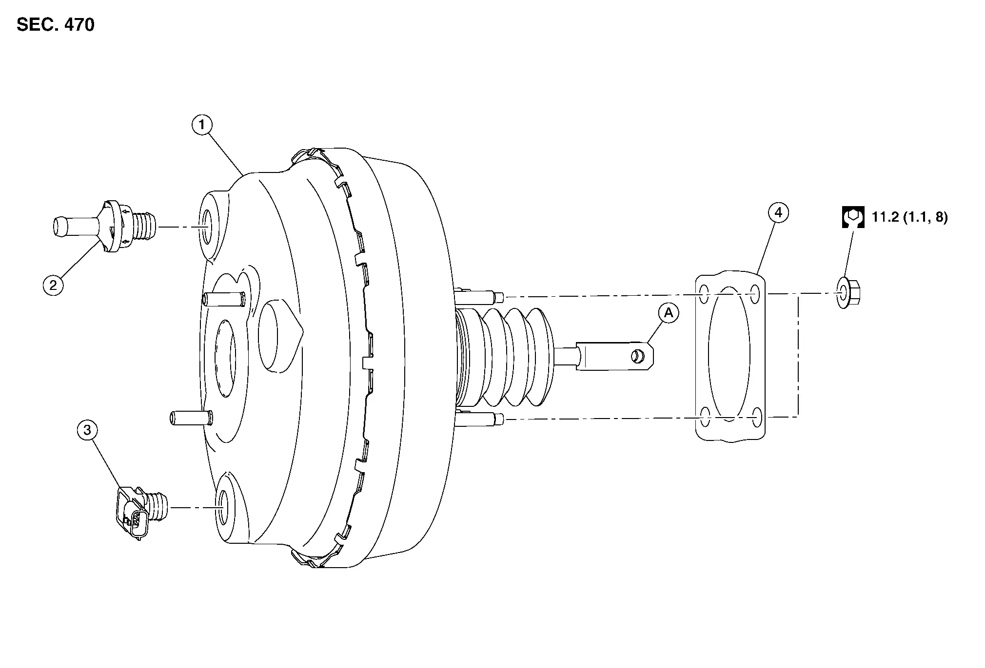
| 1. | Brake booster | 2. | Check valve | 3. | Vacuum sensor |
| 4. | Gasket | A. | Brake booster clevis |
Removal and installation
CAUTION:
-
Do not spill or splash brake fluid on painted surfaces. Brake fluid may seriously damage paint. Wipe it off immediately and wash with water if it gets on a painted surface.
-
Do not reuse drained brake fluid.
 NOTE:
NOTE:
When removing components such as hoses, tubes/lines, etc., cap or plug openings to prevent fluid from spilling.
REMOVAL
Remove the air cleaner housing. Refer to Removal and Installation.
Disconnect the harness connector from the vacuum sensor.
If necessary, remove the vacuum sensor. Refer to Exploded View.
Remove the master cylinder assembly. Refer to Removal and Installation.
CAUTION:
Do not deform or bend the brake tubes.
Loosen the hose clamp and separate the vacuum hose B from the check valve on the brake booster. Refer to Exploded View.
CAUTION:
Support the brake booster to avoid dropping or contacting other parts.
Remove the snap pin and the clevis pin from the brake booster clevis and the brake pedal assembly. Refer to Exploded View.
CAUTION:
Do not reuse the clevis pin.
Remove the nuts from the brake booster on the brake pedal side.
Remove the brake booster and the gasket.
If necessary, remove the gasket.
If necessary, remove the check valve.
INSPECTION AFTER REMOVAL
-
Measure the input rod (A) length (B).
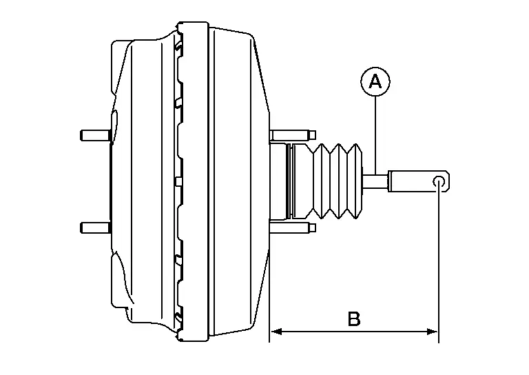
Input rod (A) length (B) : Refer to Brake Booster. -
If the input rod length is not the standard, replace the brake booster.
 NOTE:
NOTE:
The input rod length is not adjustable.
-
Make sure the vacuum sensor (2) angle (A) matches the specification for brake booster (1).
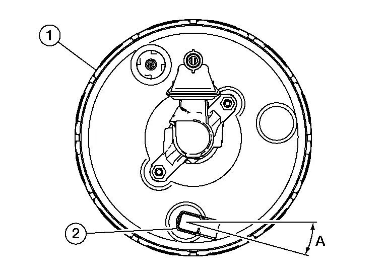
Vacuum sensor (2) angle (A) : Refer to Brake Booster.
INSTALLATION
Installation is in the reverse order of removal.
-
Apply multi-purpose grease to the clevis pin. Refer to Exploded View.
-
Bleed air from the hydraulic brake system. Refer to Bleeding Brake System.
-
Inspect the brake pedal. Refer to Inspection.
-
Inspect the brake booster. Refer to Inspection.
CAUTION:
-
Do not reuse the clevis pin.
-
Be careful not to damage brake booster stud bolt threads. If the brake booster is tilted during installation, the dash panel may damage the threads.
-
Make sure the brake hoses and tubes are not twisted or bent.
-
Replace the brake pedal if it has been dropped or sustained an impact.
Vacuum Lines Nissan Pathfinder Fifth generation
Exploded View
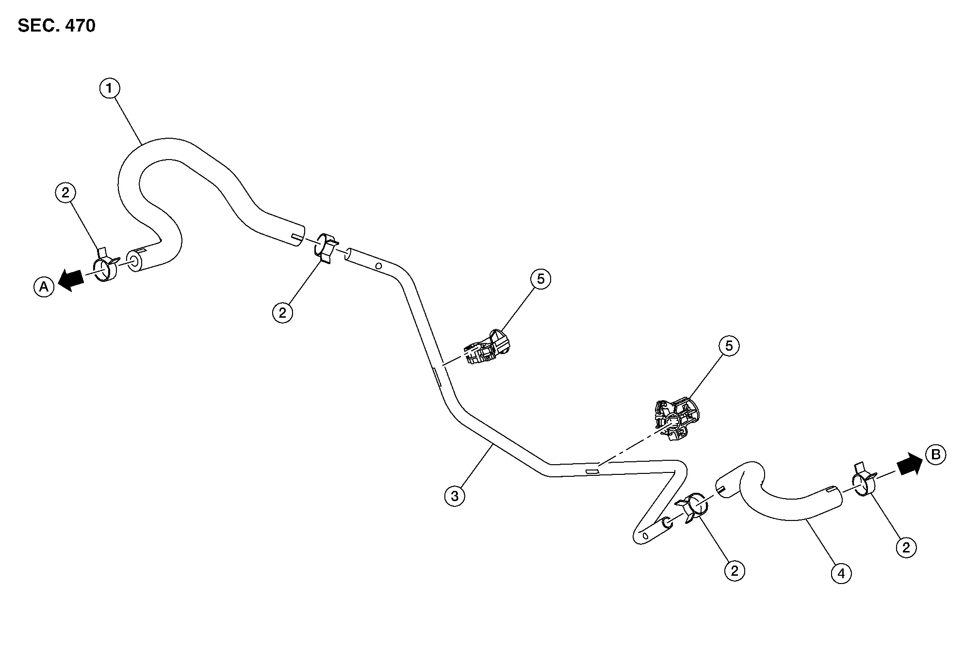
| 1. | Vacuum hose A | 2. | Hose clamp | 3. | Vacuum tube |
| 4. | Vacuum hose B | 5. | Tube clamp | A. | To intake manifold. Refer to Exploded View. |
| B. | To check valve. Refer to Exploded View. |
Removal and Installation
REMOVAL
Remove the cowl top extension. Refer to Removal and Installation.
Loosen the hose clamp and separate the vacuum hose B from the check valve on the brake booster. Refer to Exploded View.
Loosen the hose clamp and remove the vacuum hose B from the vacuum tube.
Loosen the hose clamp and separate the vacuum hose A from the vacuum tube.
Remove the vacuum tube from the tube clamps.
Loosen the hose clamp and remove the vacuum hose A from the intake manifold.
INSPECTION AFTER REMOVAL
Check for damage, deterioration, and foreign matter.
INSTALLATION
Installation is in the reverse order of removal.
-
Install the vacuum hoses and the vacuum tube in the correct position. Refer to Exploded View.
-
Install the vacuum hoses onto the vacuum tube to the specified length (A) or further as shown.
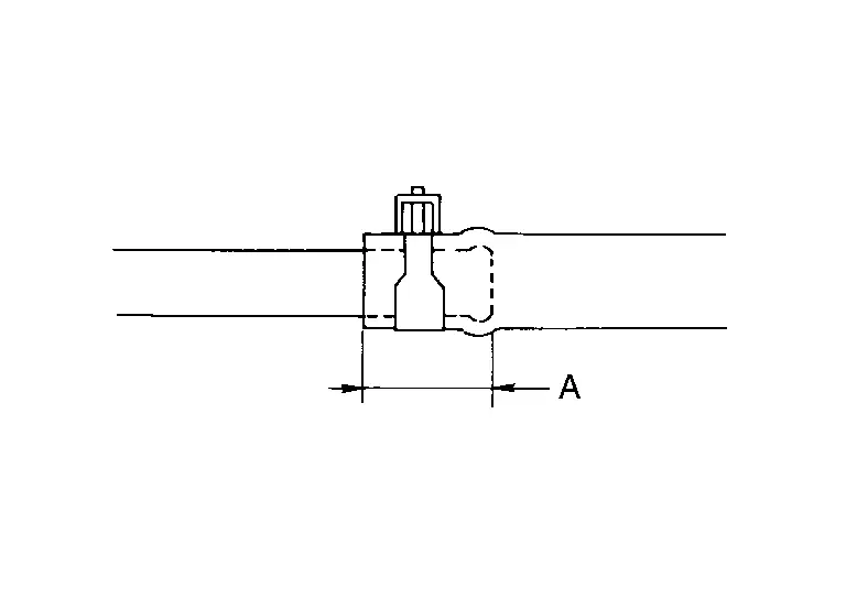
(A) : 24 mm (0.94 in) or more -
Install the hose clamp (1) onto the vacuum hose (2) to the specified length (A) from the hose end as shown.
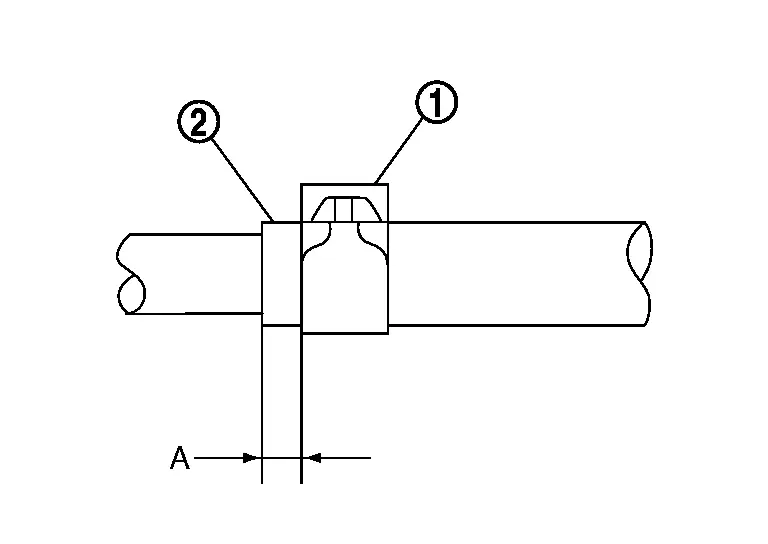
(A) : 4 – 8 mm (0.16 – 0.31 in)
CAUTION:
Do not use lubricating oil during installation.
Front Brake Pad Nissan Pathfinder Fifth generation
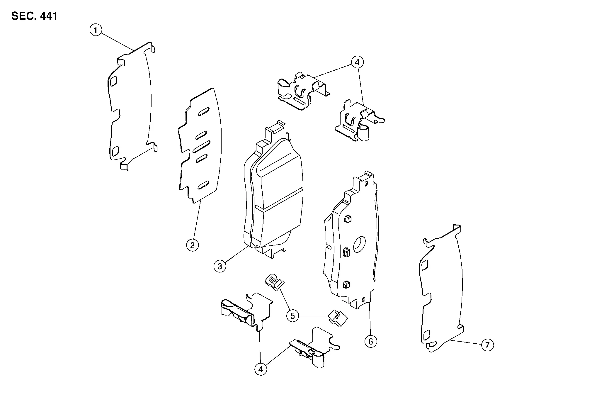
Exploded View
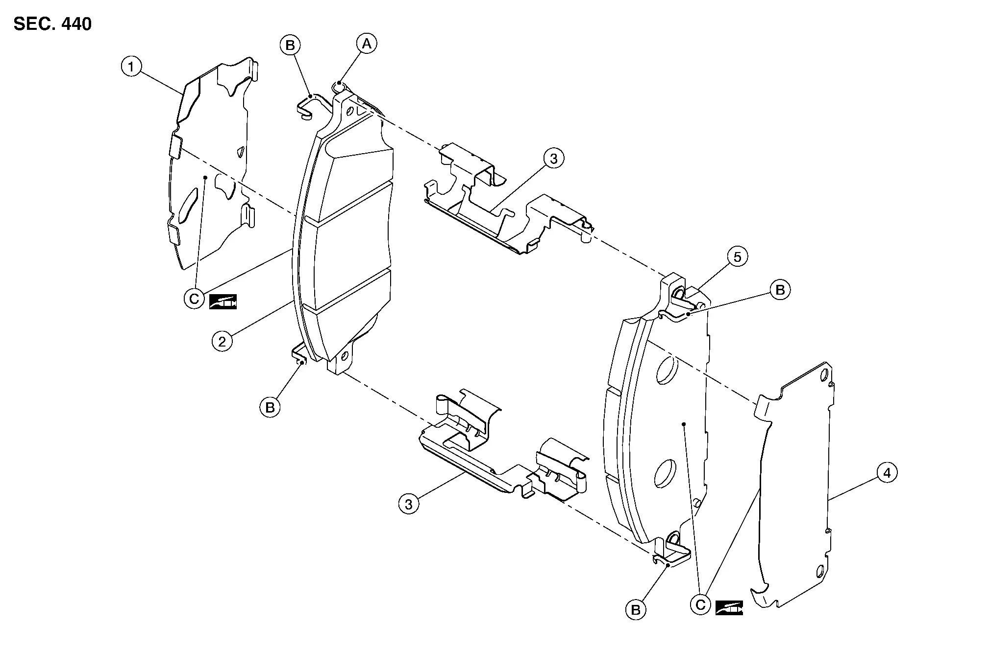
| 1. | Inner shim | 2. | Inner pad | 3. | Pad retainer |
| 4. | Outer shim | 5. | Outer pad | A. | Wear indicator |
| B. | Pad spring | C. | Molykote® AS-880N grease |
Removal and Installation
WARNING:
Clean dust on the brake caliper and the brake pads using a vacuum dust collector to minimize the hazards of airborne particles or other material.
CAUTION:
-
Do not depress the brake pedal while removing the brake pads because the piston may pop out.
-
It is not necessary to remove bolts on the torque member and the brake hose except for disassembly or replacement of the brake caliper. For brake pad removal, hang the brake caliper using a wire so as not to stretch the brake hose.
-
If brake fluid or grease adheres to the brake caliper or the disc brake rotor, quickly wipe it off.
-
Do not reuse drained brake fluid.
REMOVAL
Observe the brake fluid level in the reservoir tank. Partially drain brake fluid if necessary. Refer to Draining.
Remove the front wheel and tire using power tool. Refer to Removal and Installation.
Secure the disc brake rotor using wheel nuts.
Remove the slide pin bolts. Refer to Exploded View.
Remove the brake caliper from the torque member. Leaving the brake hose attached, reposition the brake caliper aside using wire.
Remove the slide pins from the torque member.
Remove the brake pads, shims, and pad retainers from the torque member. Refer to Exploded View.
CAUTION:
-
Do not damage the pad retainers or the piston boots.
-
Do not drop the brake pads, shims, or pad retainers.
-
Note the position of components during removal to aid with installation.
Remove the shims from the brake pads.
INSTALLATION
Install the pad retainers to the torque member. Refer to Exploded View.
CAUTION:
-
Do not deform the pad retainers.
-
Verify that the pad retainers are secured properly to the torque member.
Apply Niglube RX-2 grease to the slide pins. Refer to Exploded View.
Install the slide pins to the torque member.
Apply Molykote® AS-880N grease to the matching surfaces between the shims and the brake pads.
Install the shims to the brake pads.
Install the brake pads and the shims to the torque member.
Using a suitable tool, press the pistons into the brake caliper body.
CAUTION:
Do not damage the piston boots.
Install the brake caliper to the torque member.
Install the slide pin bolts. Tighten the slide pin bolts to the specified torque. Refer to Exploded View.
Depress the brake pedal several times and perform the inspection after installation.
Install the front wheel and tire. Refer to Removal and Installation.
Check brake fluid level and refill as necessary. Refer to Inspection.
INSPECTION AFTER INSTALLATION
Check the drag of the front disc brake. If any drag is found, perform the following procedure:Remove the brake pads. Using a suitable tool, press the pistons into the brake caliper body.
CAUTION:
Do not damage the piston boots.
Install the brake pads. Depress the brake pedal several times. Check the drag of the front disc brake again. If any drag is found, disassemble the brake caliper body. Refer to Disassembly and Assembly.Burnish contact surfaces after replacing brake pads or if a soft pedal occurs at very low mileage. Refer to Periodic Maintenance Operation.
Front Brake Caliper Assembly ➤ Nissan Pathfinder
Front Disc Brake Rotor Nissan Pathfinder
Exploded View
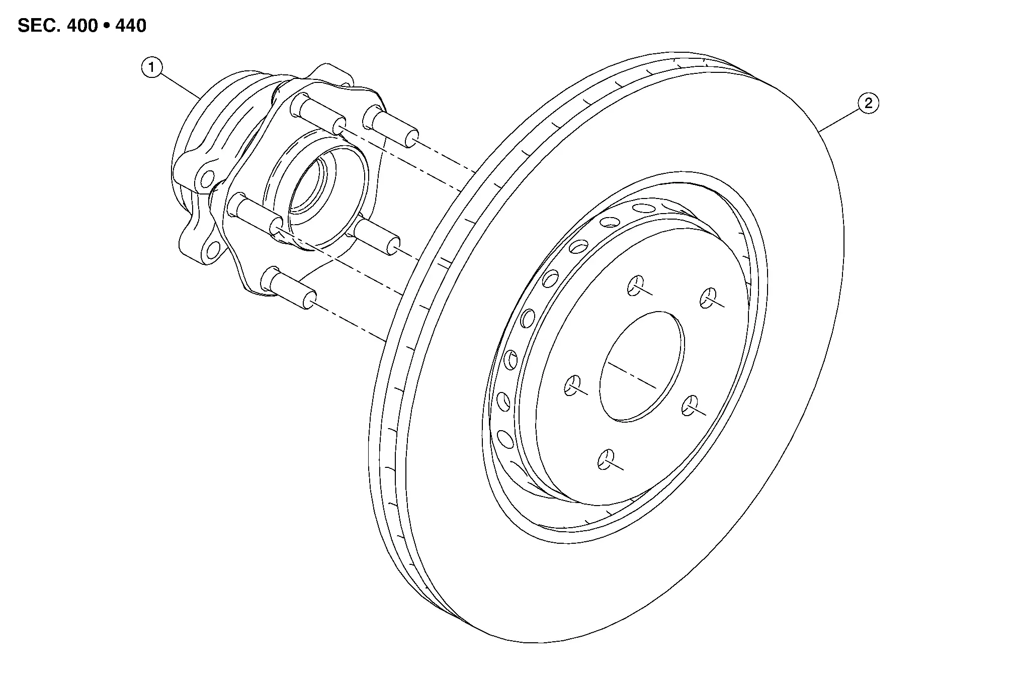
| 1. | Wheel hub and bearing | 2. | Disc brake rotor |
Removal and Installation
REMOVAL
Observe the brake fluid level in the reservoir tank. Partially drain brake fluid if necessary. Refer to Draining.
Remove the front wheel and tire using a power tool. Refer to Removal and Installation.
Remove the brake pads, shims, and pad retainers from the torque member. Refer to Removal and Installation.
CAUTION:
-
Do not damage the pad retainers or the piston boots.
-
Do not drop the brake pads, shims, or pad retainers.
-
Note the position of components during removal to aid with installation.
Remove the slide pins from the torque member. Refer to Exploded View.
Remove the bolts and the torque member.
Place alignment marks (A) on the front disc brake rotor and the wheel hub, then remove the front disc brake rotor.
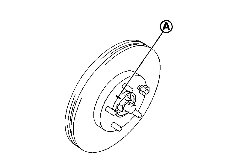
CAUTION:
Do not drop the disc brake rotor.
INSTALLATION
Installation is in the reverse order of removal.
-
Using a suitable tool, press the pistons into the brake caliper body.
CAUTION:
Do not damage the piston boots.
-
Apply Niglube RX-2 grease to the slide pins. Refer to Exploded View.
-
Check brake fluid level and refill as necessary. Refer to Inspection.
INSPECTION AFTER INSTALLATION
Burnish contact surfaces after refinishing or replacing disc brake rotors or if a soft pedal occurs at very low mileage. Refer to Periodic Maintenance Operation.
Rear Brake Pad Nissan Pathfinder SUV
Exploded View
| 1. | Inner shim cover | 2. | Inner shim | 3. | Inner pad |
| 4. | Pad retainer | 5. | Wear indicator | 6. | Outer pad |
| 7. | Outer shim |
Removal and Installation
WARNING:
Clean dust on the brake caliper and the brake pads using a vacuum dust collector to minimize the hazards of airborne particles or other material.
CAUTION:
-
Do not depress the brake pedal while removing the brake pads because the piston may pop out.
-
It is not necessary to remove bolts on the torque member and the brake hose except for disassembly or replacement of the brake caliper. For brake pad removal, hang the brake caliper using a wire so as not to stretch the brake hose.
-
If brake fluid or grease adheres to the brake caliper or the disc brake rotor, quickly wipe it off.
-
Do not reuse drained brake fluid.
REMOVAL
CAUTION:
-
Before removing the rear brake pads, perform the "REMOVAL/REPLACEMENT OF REAR BRAKE PAD OR REAR BRAKE CALIPER". Refer to Description.
-
If necessary, release the parking brake and move the piston into the brake caliper body. Perform the "INSTRUCTIONS FOR RELEASING PARKING BRAKE WHERE PARKING BRAKE SWITCH CANNOT BE USED". Refer to Description.
Observe the brake fluid level in the reservoir tank. Partially drain brake fluid if necessary. Refer to Draining.
Remove the rear wheel and tire using a power tool. Refer to Removal and Installation.
Secure the disc brake rotor using wheel nuts.
Remove the slide pin bolts. Refer to Exploded View.
Remove the brake caliper from the torque member. Leaving the brake hose attached, reposition the brake caliper aside using wire.
Remove the slide pins from the torque member..
Remove the brake pads, shims, shim cover, wear indicators, and pad retainers from the torque member. Refer to Exploded View.
CAUTION:
-
Do not damage the pad retainers or the piston boot.
-
Do not drop the brake pads, shims, shim cover, or wear indicators.
-
Note the position of components during removal to aid with installation.
INSTALLATION
Apply rubber grease to the slide pins. Refer to Exploded View.
Install the slide pins to the torque member.
Install the pad retainers to the torque member. Refer to Exploded View.
CAUTION:
-
Do not deform the pad retainers.
-
Verify that the pad retainers are secured properly to the torque member.
Install the wear indicators to the brake pads.
Install the shims to the brake pads.
Install the shim cover to the inner brake pad.
Install the brake pads, shims, shim cover, and wear indicators to the torque member.
Install the brake caliper to the torque member.
Install the slide pin bolts. Refer to Exploded View.
Depress the brake pedal several times and verify that drag does not exist.
Install the rear wheel and tire. Refer to Removal and Installation.
Check brake fluid level and refill as necessary. Refer to Inspection.
CAUTION:
-
When installing the rear brake pads, perform the "REMOVAL/REPLACEMENT OF REAR BRAKE PAD OR REAR BRAKE CALIPER". Refer to Description.
-
Perform the "ADJUSTMENT OF BRAKE CALIPER INITIAL POSITION". Refer to Description.
INSPECTION AFTER INSTALLATION
Check the drag of the rear disc brake. If any drag is found, perform the following procedure:Remove the rear brake pads.
CAUTION:
Before removing the rear brake pads, perform the "REMOVAL/REPLACEMENT OF REAR BRAKE PAD OR REAR BRAKE CALIPER". Refer to Description.
Install the brake pads.CAUTION:
-
When installing the rear brake pads, perform the "REMOVAL/REPLACEMENT OF REAR BRAKE PAD OR REAR BRAKE CALIPER". Refer to Description.
-
Perform the "ADJUSTMENT OF BRAKE CALIPER INITIAL POSITION". Refer to Description.
Burnish contact surfaces after replacing the brake pads or if a soft pedal occurs at very low mileage. Refer to Periodic Maintenance Operation.
Rear Brake Caliper Assembly ➤ Nissan Pathfinder 2022
Rear Disc Brake Rotor Nissan Pathfinder Fifth generation
Exploded View
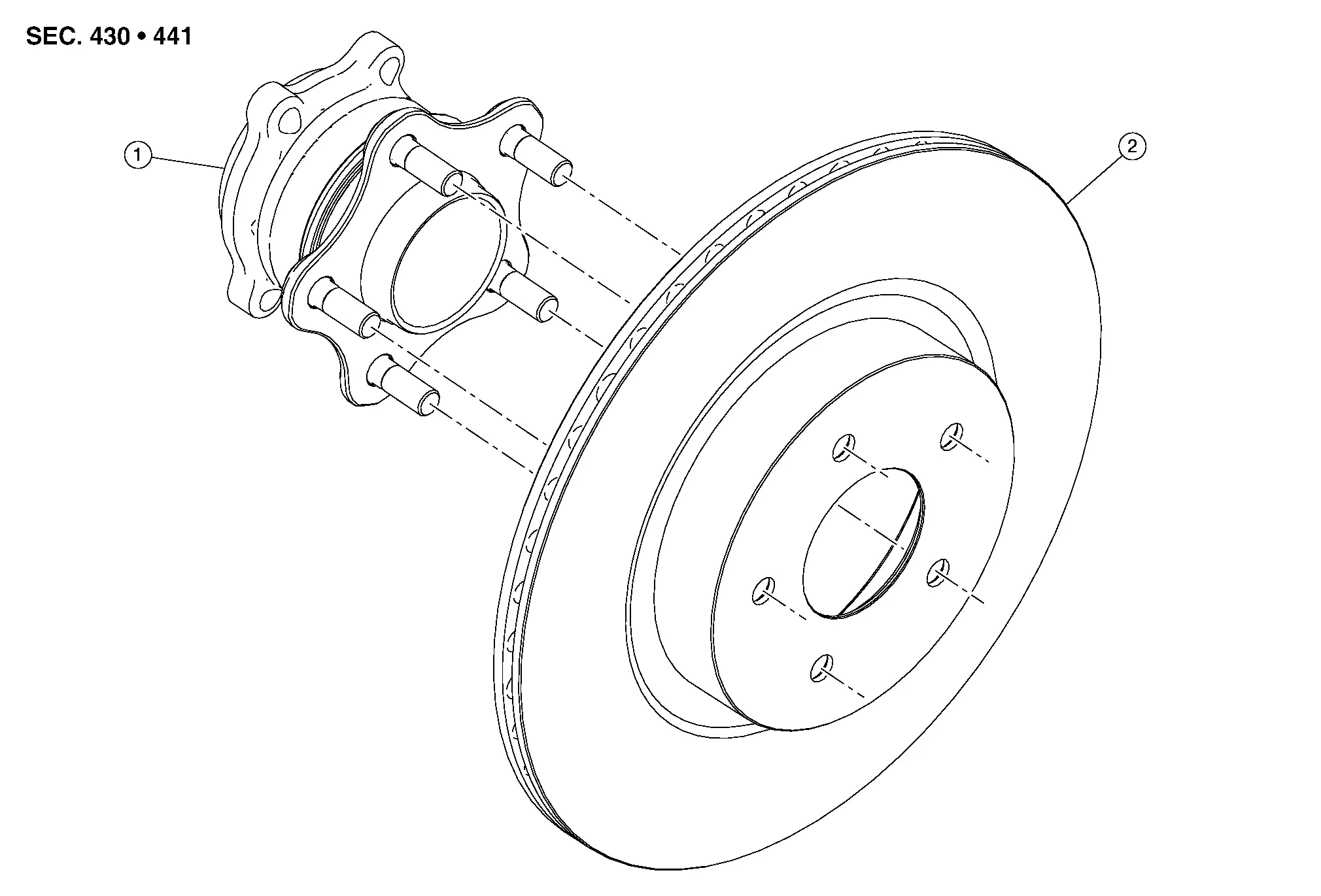
| 1. | Wheel hub and bearing | 2. | Disc brake rotor |
Removal and Installation
REMOVAL
CAUTION:
-
Before removing the rear disc brake rotor, perform the "REMOVAL/REPLACEMENT OF REAR BRAKE PAD OR REAR BRAKE CALIPER". Refer to Description.
-
If necessary, release the parking brake and move the piston into the brake caliper body. Perform the "INSTRUCTIONS FOR RELEASING PARKING BRAKE WHERE PARKING BRAKE SWITCH CANNOT BE USED". Refer to Description.
Observe the brake fluid level in the reservoir tank. Partially drain brake fluid if necessary. Refer to Draining.
Remove the rear wheel and tire using a power tool. Refer to Removal and Installation.
Remove the brake pads, shims, shim cover, and wear indicators from the torque member. Refer to Removal and Installation.
CAUTION:
-
Do not damage the pad retainers or the piston boot.
-
Do not drop the brake pads, shims, shim cover, or wear indicators.
-
Note the position of components during removal to aid with installation.
Remove the bolts and the torque member. Refer to Exploded View.
Place alignment marks (A) on the disc brake rotor and the wheel hub, then remove the disc brake rotor.

CAUTION:
Do not drop the disc brake rotor.
INSTALLATION
Installation is in the reverse order of removal.
-
Check the brake fluid level and refill as necessary. Refer to Inspection.
-
Perform the inspection after installation.
CAUTION:
-
When installing the rear disc brake rotor, perform the "REMOVAL/REPLACEMENT OF REAR BRAKE PAD OR REAR BRAKE CALIPER". Refer to Description.
-
Do not damage the piston boot.
-
INSPECTION AFTER INSTALLATION
Burnish contact surfaces after refinishing or replacing disc brake rotors or if a soft pedal occurs at very low mileage. Refer to Periodic Maintenance Operation.

Nissan Pathfinder (R53) 2022-2026 Service Manual
Removal and Installation
- Brake Pedal
- Brake Piping
- Front Brake Piping
- Brake Master Cylinder
- Brake Booster
- Vacuum Lines
- Front Brake Pad
- Front Brake Caliper Assembly ➤
- Front Disc Brake Rotor
- Rear Brake Pad
- Rear Brake Caliper Assembly ➤
- Rear Disc Brake Rotor
Contact Us
Nissan Pathfinder Info Center
Email: info@nipathfinder.com
Phone: +1 (800) 123-4567
Address: 123 Pathfinder Blvd, Nashville, TN 37214, USA
Working Hours: Mon–Fri, 9:00 AM – 5:00 PM (EST)
