Nissan Pathfinder: Dtc/circuit Diagnosis - B2720 Corner Sensor [rl] ++
DTC Description
DTC DETECTION LOGIC
| DTC No. |
CONSULT screen terms (Trouble diagnosis content) |
DTC detection condition | ||
|---|---|---|---|---|
| B2720–05 |
CORNER SENSOR [RL] (Rear sonar sensor LH outer) |
— | Diagnosis condition | Ignition switch ON |
| Signal (terminal) | — | |||
| Threshold | Rear sonar sensor LH outer configuration incomplete or wrong | |||
| Diagnosis delay time | 4 seconds or more | |||
| B2720–11 | Diagnosis condition | Ignition switch ON | ||
| Signal (terminal) | Rear sonar sensor LH outer signal (terminal 22) | |||
| Threshold | Rear sonar sensor LH outer signal circuit is short to ground | |||
| Diagnosis delay time | 4 seconds or more | |||
| B2720–12 | Diagnosis condition | Ignition switch ON | ||
| Signal (terminal) | Rear sonar sensor LH outer signal (terminal 22) | |||
| Threshold | Rear sonar sensor LH outer signal circuit is short to voltage | |||
| Diagnosis delay time | 4 seconds or more | |||
| B2720–13 | Diagnosis condition | Ignition switch ON | ||
| Signal (terminal) | Rear sonar sensor LH outer signal (terminal 22) | |||
| Threshold | Rear sonar sensor LH outer signal circuit is open | |||
| Diagnosis delay time | 4 seconds or more | |||
| B2720–16 | Diagnosis condition | Ignition switch ON | ||
| Signal (terminal) | Rear sonar sensor power supply (terminal 23) | |||
| Threshold | Rear sonar sensor power supply is greater than 27 V | |||
| Diagnosis delay time | 4 seconds or more | |||
| B2720–17 | Diagnosis condition | Ignition switch ON | ||
| Signal (terminal) | Rear sonar sensor power supply (terminal 23) | |||
| Threshold | Rear sonar sensor power supply is less than 5.2 V | |||
| Diagnosis delay time | 4 seconds or more | |||
| B2720–21 | Diagnosis condition | Ignition switch ON | ||
| Signal (terminal) | Rear sonar sensor LH outer signal (terminal 22) | |||
| Threshold | Rear sonar sensor LH outer signal amplitude is small | |||
| Diagnosis delay time | 4 seconds or more | |||
| B2720–29 | Diagnosis condition | Ignition switch ON | ||
| Signal (terminal) | Rear sonar sensor LH outer signal (terminal 22) | |||
| Threshold | Rear sonar sensor LH outer signal is abnormal | |||
| Diagnosis delay time | 4 seconds or more | |||
| B2720–34 | Diagnosis condition | Ignition switch ON | ||
| Signal (terminal) | Rear sonar sensor LH outer signal (terminal 22) | |||
| Threshold | Rear sonar sensor LH outer signal is abnormal (pulse signal high side is short) | |||
| Diagnosis delay time | 4 seconds or more | |||
| B2720–35 | Diagnosis condition | Ignition switch ON | ||
| Signal (terminal) | Rear sonar sensor LH outer signal (terminal 22) | |||
| Threshold | Rear sonar sensor LH outer signal is abnormal (pulse signal high side is long) | |||
| Diagnosis delay time | 4 seconds or more | |||
| B2720–43 | Diagnosis condition | Ignition switch ON | ||
| Signal (terminal) | — | |||
| Threshold | Sonar control unit internal malfunction | |||
| Diagnosis delay time | 4 seconds or more | |||
| B2720–47 | Diagnosis condition | Ignition switch ON | ||
| Signal (terminal) | — | |||
| Threshold | Sonar control unit sensor data lost | |||
| Diagnosis delay time | 4 seconds or more | |||
| B2720–49 | Diagnosis condition | Ignition switch ON | ||
| Signal (terminal) | — | |||
| Threshold | Sonar control unit internal malfunction | |||
| Diagnosis delay time | 4 seconds or more | |||
| B2720–61 | Diagnosis condition | Ignition switch ON | ||
| Signal (terminal) | — | |||
| Threshold | Sonar control unit internal malfunction | |||
| Diagnosis delay time | 4 seconds or more | |||
| B2720–65 | Diagnosis condition | Ignition switch ON | ||
| Signal (terminal) | — | |||
| Threshold | Rear sonar sensor LH outer temperature is high | |||
| Diagnosis delay time | 4 seconds or more | |||
| B2720–66 | Diagnosis condition | Ignition switch ON | ||
| Signal (terminal) | Rear sonar sensor LH outer signal (terminal 22) | |||
| Threshold | Rear sonar sensor LH outer signal circuit is open or short to ground | |||
| Diagnosis delay time | — | |||
| B2720–68 | Diagnosis condition | Ignition switch ON | ||
| Signal (terminal) | — | |||
| Threshold | Rear sonar sensor LH outer magnetic noise detected | |||
| Diagnosis delay time | 4 seconds or more | |||
| B2720–81 | Diagnosis condition | Ignition switch ON | ||
| Signal (terminal) | Rear sonar sensor LH outer signal (terminal 22) | |||
| Threshold | Rear sonar sensor LH outer signal abnormal | |||
| Diagnosis delay time | 4 seconds or more | |||
| B2720–83 | Diagnosis condition | Ignition switch ON | ||
| Signal (terminal) | Rear sonar sensor LH outer signal (terminal 22) | |||
| Threshold | Rear sonar sensor LH outer signal is abnormal | |||
| Diagnosis delay time | 4 seconds or more | |||
| B2720–88 | Diagnosis condition | Ignition switch ON | ||
| Signal (terminal) | — | |||
| Threshold | Communication error | |||
| Diagnosis delay time | 4 seconds or more | |||
| B2720–92 | Diagnosis condition | Ignition switch ON | ||
| Signal (terminal) | Rear sonar sensor LH outer signal (terminal 22) | |||
| Threshold | Rear sonar sensor LH outer signal is abnormal | |||
| Diagnosis delay time | 4 seconds or more | |||
| B2720–93 | Diagnosis condition | Ignition switch ON | ||
| Signal (terminal) | Rear sonar sensor LH outer signal (terminal 22) | |||
| Threshold | Rear sonar sensor LH outer signal is abnormal | |||
| Diagnosis delay time | 4 seconds or more | |||
| B2720–95 | Diagnosis condition | Ignition switch ON | ||
| Signal (terminal) | Rear sonar sensor LH outer signal (terminal 22) | |||
| Threshold | Rear sonar sensor LH outer signal is abnormal | |||
| Diagnosis delay time | 4 seconds or more | |||
| B2720–96 | Diagnosis condition | Ignition switch ON | ||
| Signal (terminal) | Rear sonar sensor LH outer signal (terminal 22) | |||
| Threshold | Rear sonar sensor LH outer signal is abnormal | |||
| Diagnosis delay time | 4 seconds or more | |||
| B2720–97 | Diagnosis condition | Ignition switch ON | ||
| Signal (terminal) | — | |||
| Threshold | Rear sonar sensor LH outer is covered with ice or mud | |||
| Diagnosis delay time | 4 seconds or more | |||
POSSIBLE CAUSE
-
Configuration
-
Harness or connectors
-
Rear sonar sensor LH outer temperature is high
-
Rear sonar sensor LH outer magnetic noise is detected
-
Rear sonar sensor LH outer is covered with ice or mud
-
Rear sonar sensor LH outer
-
Sonar control unit
FAIL-SAFE
Obstacle detection function is deactivated
DTC Confirmation Procedure
DTC CONFIRMATION PROCEDURE
 CONSULT
-
Ignition switch ON.
-
Ignition switch OFF and wait at least 30 seconds.
-
Ignition switch ON and wait at least 30 seconds or more.
-
Select “Self Diagnostic Result” mode of “SONAR”.
-
Check the DTC.
Is DTC B2720 detected?
YES>>
Refer to Diagnosis Procedure.
NO>>
To check malfunction symptom before repair: Refer to Intermittent Incident.
NO>>
Confirmation after repair: Inspection End.
Diagnosis Procedure
DETERMINE MALFUNCTION TYPE
 CONSULT
-
Ignition switch ON.
-
Ignition switch OFF and wait at least 30 seconds.
-
Ignition switch ON and wait at least 30 seconds or more.
-
Select “Self Diagnostic Result” mode of “SONAR”.
-
Check the DTC.
Is DTC B2720–05, 11, 12, 13, 16, 17, 21, 29, 34, 35, 43, 47, 49, 61, 65, 66, 68, 81, 83, 88, 92, 93, 95 or 97 detected?
YES>>
11, 66 or 88 – GO TO 2.
YES>>
12 – GO TO 3.
YES>>
13, 21, 29, 34 or 35 – GO TO 4.
YES>>
16 or 17 – GO TO 7.
YES>>
65 – GO TO 8.
YES>>
68 – GO TO 9.
YES>>
97 – GO TO 10.
YES>>
05 or 47 – GO TO 11.
YES>>
43, 49, 61, 81, 83, 92, 93, 95 or 96 – GO TO 12.
NO>>
Refer to Intermittent Incident.
CHECK REAR SONAR SENSOR LH OUTER SIGNAL CIRCUIT FOR SHORT TO GROUND
-
Ignition switch OFF.
-
Disconnect sonar control unit and rear sonar sensor LH outer connectors.
-
Check continuity between sonar control unit connector and ground.
Sonar control unit Ground Continuity Connector Terminal M70 22 — No
Is the inspection result normal?
YES>>
11 – GO TO 6.
YES>>
88 – GO TO 3.
YES>>
66 – GO TO 4.
NO>>
Repair or replace harness or connectors.
CHECK REAR SONAR SENSOR LH OUTER SIGNAL CIRCUIT FOR SHORT TO VOLTAGE
-
Ignition switch OFF.
-
Disconnect sonar control unit and rear sonar sensor LH outer connectors.
-
Ignition switch ON.
-
Check the voltage between sonar control unit connector and ground.
Sonar control unit — Voltage
(Approx.)Connector Terminal M70 22 Ground 0 V
Is the inspection result normal?
YES>>
GO TO 6.
NO>>
Repair or replace harness or connectors.
CHECK REAR SONAR SENSOR LH OUTER GROUND CIRCUIT FOR OPEN
-
Ignition switch OFF.
-
Disconnect sonar control unit and rear sonar sensor LH outer connectors.
-
Check continuity between sonar control unit connector and rear sonar sensor LH outer connector.
Sonar control unit Rear sonar sensor LH outer Continuity Connector Terminal Connector Terminal M70 22 B466 2 Yes
Is the inspection result normal?
YES>>
GO TO 5.
NO>>
Repair or replace harness or connectors.
CHECK REAR SONAR SENSOR LH OUTER GROUND CIRCUIT FOR OPEN
-
Check continuity between sonar control unit connector and rear sonar sensor LH outer connector.
Sonar control unit Rear sonar sensor LH outer Continuity Connector Terminal Connector Terminal M70 14 B466 3 Yes
Is the inspection result normal?
YES>>
GO TO 6.
NO>>
Repair or replace harness or connectors.
CHECK REAR SONAR SENSOR LH OUTER SIGNAL
-
Connect sonar control unit and rear sonar sensor LH outer connectors.
-
Ignition switch ON.
-
Check signal between the terminals of sonar control unit connector.
Sonar control unit Condition Reference value Connector (+) (−) Terminal Terminal M70 22 14 Sensor signal input 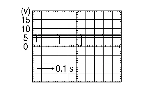
Is the inspection result normal?
YES>>
Replace sonar control unit. Refer to Removal and Installation.
NO>>
Replace rear sonar sensor LH outer. Refer to Removal and Installation.
CHECK REAR SONAR SENSOR POWER SUPPLY CIRCUIT
Check rear sonar sensor power supply circuit. Refer to DTC Description.
Is the inspection result normal?
YES>>
Inspection End.
NO>>
Repair or replace harness or connectors.
CHECK SONAR SENSOR TEMPERATURE
Check whether there is any factor which causes a temperature rise near sonar sensor.
Was there any factor?
YES>>
Remove factor.
NO>>
GO TO 12.
CHECK SONAR SENSOR NOISE
Check if there is any noise generating factor near sonar sensor.
Was there any factor?
YES>>
Remove factor.
NO>>
GO TO 12.
CHECK SONAR SENSOR BLOCKAGE
Make sure that the sonar sensor is not covered with snow or mud.
Is the sonar sensor covered with snow or mud?
YES>>
Clean the sonar sensor.
NO>>
GO TO 12.
PERFORM CONFIGURATION OF SONAR CONTROL UNIT
Perform configuration of sonar control unit. Refer to Description.
YES>>
GO TO 12.
PERFORM DTC CONFIRMATION PROCEDURE AGAIN
 CONSULT
-
Ignition switch ON.
-
Ignition switch OFF and wait at least 30 seconds.
-
Ignition switch ON and wait at least 30 seconds or more.
-
Select “Self Diagnostic Result” mode of “SONAR”.
-
Check the DTC.
Is DTC B2720–05, 43, 47, 49, 61, 65, 68, 81, 83, 92, 93, 95, 96 or 97 detected?
YES>>
05, 47, 65, 68, 81, 83, 92, 93, 95, 96 or 97, replace rear sonar sensor LH outer. Refer to Removal and Installation.
YES>>
43, 49 or 61, replace sonar control unit. Refer to Removal and Installation.
NO>>
Inspection End.

Nissan Pathfinder (R53) 2022-2026 Service Manual
Contact Us
Nissan Pathfinder Info Center
Email: info@nipathfinder.com
Phone: +1 (800) 123-4567
Address: 123 Pathfinder Blvd, Nashville, TN 37214, USA
Working Hours: Mon–Fri, 9:00 AM – 5:00 PM (EST)
