Nissan Pathfinder: Door & Lock - Dtc/circuit Diagnosis
- Ajar Switch
- Back Door Opener Actuator
- Back Door Opener Switch
- Back Door Request Switch
- Door Request Switch
- Door Switch
- Hazard Function
- Intelligent Key Battery
- Intelligent Key Warning Buzzer
- Touch Sensor
- Unlock Sensor
- 4022 B2001-45 Intelligent Key Unit
- 4022 B2010-1c Battery Voltage
- 4022 B203c-14 Inside Antenna
- 4022 B203e-14 Outside Antenna
- 4022 B2046-42 Eeprom
- 4022 B2087 One Touch Sensor (fl)
- 4022 B2086-23: Request Sw (bd/tr)
- 4022 B2409-12 Half Latch Switch
- 4022 B2409-14 Half Latch Switch
- 4022 B2417-15 Touch Sensor Circuit Lh Open
- 4023 B2419-12 Open Switch
- 4023 B2419-14 Open Switch
- 4023 B2422-78 Back Door Position Abnormal
- 4023 B2426-11 Spindle Sensor Lh
- 4023 B2426-12 Spindle Sensor Lh
- 4023 B2426-13 Spindle Sensor Lh
- 4023 B2426-25 Spindle Sensor Lh
- 4023 B2428-44 Automatic Back Door Control Unit
- 4023 B2428-52 Automatic Back Door Control Unit
- 4023 B2428-54 Automatic Back Door Control Unit
- 4024 B242a-98 Closure Motor
- 4024 B2436-11 Spindle Motor Lh
- 4024 B2436-12 Spindle Motor Lh
- 4024 B2436-98 Spindle Motor Lh
- 4024 B2f06-11 Trunk/back Door Opener Sw
- 4024 U0075-00 Communication Bus C Off
- 4024 U2140-87 Can Ecm
- 4024 U2141-87 Communication Lost with Atcu
- 4024 Automatic Back Door Close Switch
- 4024 Automatic Back Door Serial Communication
Ajar Switch Nissan Pathfinder
ComponentFunctionCheck
CHECK FUNCTION
 CONSULT
-
Ignition switch ON.
-
Select “TRUNK” of “BCM”.
-
Select “Back door/trunk lid switch” in “DATA MONITOR” mode.
-
Check that the function operates normally according to the following conditions.
| Monitor item | Condition | Status | |
|---|---|---|---|
| Back door/trunk lid switch | Back door | Open | On |
| Closed | Off | ||
Is the inspection result normal?
YES>>Back door switch is OK.
NO>>Refer to Diagnosis Procedure.
Diagnosis Procedure
CHECK AJAR SWITCH INPUT SIGNAL
-
Ignition switch OFF.
-
Disconnect back door lock assembly connector.
-
Check voltage between back door lock assembly harness connector and ground.
(+) (–) Voltage
(Approx.)Back door lock assembly Connector Terminal D557 7 Ground Battery voltage
Is the inspection result normal?
YES>>GO TO 3.
NO>>GO TO 2.
CHECK AJAR SWITCH CIRCUIT
-
Disconnect BCM connector.
-
Check continuity between back door lock assembly harness connector and BCM harness connector.
Back door lock assembly BCM Continuity Connector Terminal Connector Terminal D557 7 B59 96 Yes -
Check continuity between back door lock assembly harness connector and ground.
Back door lock assembly (-) Continuity Connector Terminal D557 7 Ground No
Is the inspection result normal?
YES>>Replace BCM. Refer to Removal and Installation.
NO>>Repair or replace harness.
CHECK AJAR SWITCH GROUND CIRCUIT
Check continuity between back door lock assembly harness connector and ground.
| Back door lock assembly | (-) | Continuity | |
|---|---|---|---|
| Connector | Terminal | ||
| D557 | 8 | Ground | Yes |
Is the inspection result normal?
YES>>GO TO 4.
NO>>Repair or replace harness.
CHECK AJAR SWITCH
Refer to Component Inspection.
Is the inspection result normal?
YES>>GO TO 5.
NO>>Replace back door lock assembly. Refer to Removal and Installation.
CHECK INTERMITTENT INCIDENT
Refer to Intermittent Incident.
>>
Inspection End.
Component Inspection
CHECK AJAR SWITCH
-
Ignition switch OFF.
-
Disconnect back door lock assembly connector.
-
Check continuity between back door lock assembly terminals.
Back door lock assembly Condition Continuity Terminal 7 8 Back door Open Yes Close No
Is the inspection result normal?
YES>>Inspection End.
NO>>Replace back door lock assembly. Refer to Removal and Installation.
Back Door Opener Actuator Nissan Pathfinder
ComponentFunctionCheck
CHECK FUNCTION
 CONSULT
-
Ignition switch ON.
-
Select “TRUNK” of “BCM”.
-
Select “Trunk/back door” in “ACTIVE TEST” mode.
-
Check that the function operates normally according to the following conditions.
Monitor item Status Trunk/back door On Back door OPEN
Is the inspection result normal?
YES>>Back door opener actuator is OK.
NO>>Refer to Diagnosis Procedure.
Diagnosis Procedure
CHECK BACK DOOR OPENER ACTUATOR INPUT SIGNAL
-
Ignition switch OFF.
-
Disconnect back door lock assembly connector.
-
Check voltage between back door lock assembly harness connector and ground.
| (+) | (–) | Condition |
Voltage (Approx.) | ||
|---|---|---|---|---|---|
| Back door lock assembly | |||||
| Connector | Terminal | ||||
| D557 | 4 | Ground | Back door opener switch | ON | Battery voltage |
Is the inspection result normal?
YES>>GO TO 3.
NO>>GO TO 2.
CHECK BACK DOOR OPENER ACTUATOR CIRCUIT
-
Disconnect back door control module connector.
-
Check continuity between back door control module harness connector and back door lock assembly harness connector.
Back door control module Back door lock assembly Continuity Connector Terminal Connector Terminal B55 11 D557 4 Yes -
Check continuity between back door control module harness connector and ground.
Back door control module — Continuity Connector Terminal B55 11 Ground No
Is the inspection result normal?
YES>>Replace automatic back door control unit. Refer to Removal and Installation.
NO>>Repair or replace harness.
CHECK BACK DOOR OPENER ACTUATOR GROUND CIRCUIT
Check continuity between back door lock assembly harness connector and ground.
| Back door lock assembly | — | Continuity | |
|---|---|---|---|
| Connector | Terminal | ||
| D557 | 8 | Ground | Yes |
Is the inspection normal?
YES>>Replace back door lock assembly. Refer to Removal and Installation.
NO>>Repair or replace harness.
Back Door Opener Switch Nissan Pathfinder Fifth generation
ComponentFunctionCheck
CHECK FUNCTION
 CONSULT
-
Ignition switch ON.
-
Select “TRUNK” of “BCM”.
-
Select “Request switch BD/TR” in “DATA MONITOR” mode.
-
Check that the function operates normally according to the following conditions.
| Monitor item | Condition | Status | |
|---|---|---|---|
| Request switch BD/TR | Back door opener switch | Pressed | On |
| Released | Off | ||
Is the inspection result normal?
YES>>Back door opener switch is OK.
NO>>Refer to Diagnosis Procedure.
Diagnosis Procedure
CHECK BACK DOOR OPEN INPUT SIGNAL
-
Ignition switch OFF.
-
Disconnect back door opener switch connector.
-
Check voltage between back door opener switch harness connector and ground.
(+) (–) Voltage
(Approx.)Back door opener switch Connector Terminal D559 1 Ground Battery voltage
Is the inspection result normal?
YES>>GO TO 3.
NO>>GO TO 2.
CHECK BACK DOOR OPENER SWITCH CIRCUIT
-
Disconnect BCM connector.
-
Check continuity between BCM harness connector and back door opener switch harness connector.
BCM Back door opener switch Continuity Connector Terminal Connector Terminal B59 98 D559 1 Yes -
Check continuity between BCM harness connector and ground.
BCM — Continuity Connector Terminal B59 98 Ground No
Is the inspection result normal?
YES>>Replace BCM. Refer to Removal and Installation.
NO>>Repair or replace harness.
CHECK BACK DOOR OPENER SWITCH GROUND CIRCUIT
Check continuity between back door opener switch harness connector and ground.
| Back door opener switch | — | Continuity | |
|---|---|---|---|
| Connector | Terminal | ||
| D559 | 2 | Ground | Yes |
Is the inspection result normal?
YES>>GO TO 4.
NO>>Repair or replace harness.
CHECK BACK DOOR OPENER SWITCH
Refer to Component Inspection.
Is the inspection result normal?
YES>>GO TO 5.
NO>>Replace back door opener switch. Refer to Removal and Installation.
CHECK INTERMITTENT INCIDENT
Refer to Intermittent Incident.
>>
Inspection End.
Component Inspection
CHECK BACK DOOR OPENER SWITCH
-
Ignition switch OFF.
-
Disconnect back door opener switch connector.
-
Check continuity between back door opener switch terminals.
Back door opener switch Condition Continuity Terminal 1 2 Back door opener switch Pressed Yes Released No
Is the inspection result normal?
YES>>Inspection End.
NO>>Replace back door opener switch. Refer to Removal and Installation.
Back Door Request Switch Nissan Pathfinder 2026
Component Inspection
CHECK BACK DOOR REQUEST SWITCH
-
Ignition switch OFF.
-
Disconnect back door opener switch connector.
-
Check back door opener switch terminals.
| Back door opener switch | Condition | Continuity | ||
|---|---|---|---|---|
| Terminal | ||||
| 3 | 4 | Back door request switch | Pressed | Yes |
| Released | No | |||
Is the inspection result normal?
YES>>Inspection End.
NO>>Replace back door opener switch. Refer to Removal and Installation.
Door Request Switch Nissan Pathfinder
Component Inspection
CHECK DOOR REQUEST SWITCH
-
Ignition switch OFF.
-
Disconnect malfunctioning door request switch connector.
-
Check continuity between malfunctioning door request switch terminals.
| Door request switch | Condition | Continuity | ||
|---|---|---|---|---|
| Terminal | ||||
| 1 | 2 | Door request switch | Pressed | Yes |
| Released | No | |||
Is the inspection result normal?
YES>>Inspection End.
NO>>Replace outside handle. Refer to Removal and Installation (front door) or Removal and Installation (rear door).
Door Switch Nissan Pathfinder SUV
ComponentFunctionCheck
CHECK FUNCTION
 CONSULT
-
Select “DOOR LOCK” of “BCM”.
-
Select “DOOR SW-DR”, “Door switch AS”, “DOOR SW-RL” and “DOOR SW-RR” in “DATA MONITOR” mode.
-
Check that the function operates normally according to the following conditions.
| Monitor item | Condition | Status | |
|---|---|---|---|
| DOOR SW-DR | Front door LH | Open | On |
| Closed | Off | ||
| Door switch AS | Front door RH | Open | On |
| Closed | Off | ||
| DOOR SW-RL | Rear door LH | Open | On |
| Closed | Off | ||
| DOOR SW-RR | Rear door RH | Open | On |
| Closed | Off | ||
Is the inspection result normal?
YES>>Door switch is OK.
NO>>Refer to Diagnosis Procedure.
Diagnosis Procedure
CHECK DOOR SWITCH INPUT SIGNAL
-
Ignition switch OFF.
-
Disconnect malfunctioning door lock assembly connector.
-
Check voltage between malfunctioning door lock assembly harness connector and ground.
(+) (–) Voltage
(Approx.)Door lock assembly Connector Terminal Front LH D14 5 Ground Battery voltage Front RH D114 8 Rear LH D205 5 Rear RH D305 8
Is the inspection result normal?
YES>>GO TO 3.
NO>>GO TO 2.
CHECK DOOR SWITCH CIRCUIT
-
Disconnect BCM connector.
-
Check continuity between door lock assembly harness connector and BCM harness connector.
Door lock assembly BCM Continuity Connector Terminal Connector Terminal Front LH D14 5 B59 81 Yes Front RH D114 8 93 Rear LH D205 5 94 Rear RH D305 8 95 -
Check continuity between door lock assembly harness connector and ground.
Door lock assembly — Continuity Connector Terminal Front LH D14 5 Ground No Front RH D114 8 Rear LH D205 5 Rear RH D305 8
Is the inspection result normal?
YES>>Replace BCM. Refer to Removal and Installation.
NO>>Repair or replace harness.
CHECK DOOR SWITCH GROUND CIRCUIT
Check continuity between door lock assembly harness connector and ground.
| Door lock assembly | — | Continuity | ||
|---|---|---|---|---|
| Connector | Terminal | |||
| Front LH | D14 | 6 | Ground | Yes |
| Front RH | D114 | 7 | ||
| Rear LH | D205 | 6 | ||
| Rear RH | D305 | 7 | ||
YES>>
GO TO 4.
NO>>Repair or replace harness.
CHECK DOOR SWITCH
Refer to Component Inspection.
Is the inspection result normal?
YES>>GO TO 5.
NO>>Replace malfunctioning door lock assembly. Refer to Removal and Installation (front door) or Removal and Installation (rear door).
CHECK INTERMITTENT INCIDENT
Refer to Intermittent Incident.
>>
Inspection End.
Component Inspection
CHECK DOOR SWITCH
-
Ignition switch OFF.
-
Disconnect malfunctioning door lock assembly connector.
-
Check continuity between door lock assembly terminals.
Door lock assembly Condition Continuity Terminal Front LH 5 6 Door Closed No Opened Yes Front RH 7 8 Closed No Opened Yes Rear LH 5 6 Closed No Opened Yes Rear RH 7 8 Closed No Opened Yes
Is the inspection result normal?
YES>>Inspection End.
NO>>Replace malfunctioning door lock assembly. Refer to Removal and Installation (front door) or Removal and Installation (rear door).
Hazard Function Nissan Pathfinder 2026
ComponentFunctionCheck
CHECK FUNCTION
 CONSULT
-
Select “FLASHER” of “BCM”.
-
Select “FLASHER” in “ACTIVE TEST” mode.
-
Touch “LH” or “RH” to check that it works normally.
Is the inspection result normal?
YES>>Hazard warning lamp circuit is OK.
NO>>Refer to Diagnosis Procedure.
Diagnosis Procedure
CHECK HAZARD OPERATION
Refer to System Description.
Is the inspection result normal?
YES>>GO TO 2.
NO>>Refer to Symptom Table.
CHECK INTERMITTENT INCIDENT
Refer to Intermittent Incident.
>>
Inspection End.
Intelligent Key Battery Nissan Pathfinder 2026
Component Inspection
CHECK INTELLIGENT KEY BATTERY
Check by connecting a resistance (approximately 300 Ω) so that the current value becomes about 10 mA. Refer to Removal and Installation.
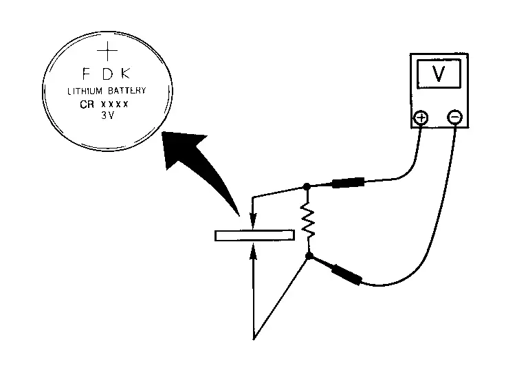
| Standard | : Approx. 2.5 - 3.0 V |
Is the measurement value within the specification?
YES>>Inspection End.
NO>>Replace Intelligent Key battery.
Intelligent Key Warning Buzzer Nissan Pathfinder 2026
Diagnosis Procedure
CHECK INTELLIGENT KEY WARNING BUZZER POWER SUPPLY CIRCUIT
-
Ignition switch OFF.
-
Check signal between Intelligent Key warning buzzer harness connector and ground using oscilloscope.
(+) (–) Condition Signal
(Reference value)Intelligent Key warning buzzer Connector Terminal B408 1 Ground Sounding
 NOTE:
NOTE:
The pulse cycle changes depending on buzzer sounds.
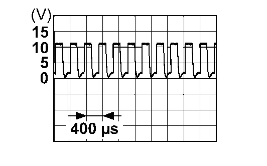
Is the inspection result normal?
YES>>GO TO 3.
NO>>GO TO 2.
CHECK INTELLIGENT KEY WARNING BUZZER CIRCUIT
-
Disconnect Intelligent Key unit connector and Intelligent Key warning buzzer connector.
-
Check continuity between Intelligent Key unit harness connector and Intelligent Key warning buzzer harness connector.
Intelligent Key unit Intelligent Key warning buzzer Continuity Connector Terminal Connector Terminal M38 3 B408 1 Yes -
Check continuity between Intelligent Key unit harness connector and ground.
Intelligent Key unit — Continuity Connector Terminal M38 3 Ground No
Is the inspection result normal?
YES>>Replace Intelligent Key unit. Refer to Removal and Installation.
NO>>Repair or replace harness.
CHECK INTELLIGENT KEY WARNING BUZZER GROUND CIRCUIT
Check continuity between Intelligent Key warning buzzer harness connector and ground.
| Intelligent Key warning buzzer | — | Continuity | |
|---|---|---|---|
| Connector | Terminal | ||
| B408 | 2 | Ground | Yes |
Is the inspection result normal?
YES>>GO TO 4.
NO>>Repair or replace harness.
CHECK INTELLIGENT KEY WARNING BUZZER
Check Intelligent Key warning buzzer. Refer to Component Inspection.
Is the inspection result normal?
YES>>Check intermittent incident. Refer to Intermittent Incident.
NO>>Replace Intelligent Key warning buzzer. Refer to Removal and Installation.
Component Inspection
CHECK INTELLIGENT KEY WARNING BUZZER
-
Ignition switch OFF.
-
Disconnect Intelligent Key warning buzzer connector.
-
Connect battery power supply directly to Intelligent Key warning buzzer terminals and check the operation.
Intelligent Key warning buzzer Operation Terminal (+) (−) 1 2 Buzzer sounds
Is the inspection result normal?
YES>>Inspection End.
NO>>Replace Intelligent Key warning buzzer. Refer to Removal and Installation.
Touch Sensor Nissan Pathfinder 2026
Component Inspection
CHECK TOUCH SENSOR
-
Ignition switch OFF.
-
Disconnect touch sensor connector.
-
Check resistance between touch sensor terminals.
| Touch sensor | Condition | Resistance | ||
|---|---|---|---|---|
| Terminal | ||||
| 1 | 4 | Touch sensor | Detect obstruction | 400 Ω or less |
| Other than above | 0.95 – 1.05 kΩ | |||
Is the inspection result normal?
YES>>Inspection End.
NO>>Replace touch sensor. Refer to Removal and Installation.
Unlock Sensor Nissan Pathfinder 5th Gen
Diagnosis Procedure
CHECK UNLOCK SENSOR INPUT SIGNAL
-
Ignition switch OFF.
-
Disconnect front door lock assembly LH connector.
-
Check voltage between front door lock assembly LH harness connector and ground.
(+) (–) Voltage
(Approx.)Front door lock assembly LH Connector Terminal D14 7 Ground Battery voltage
Is the inspection result normal?
YES>>GO TO 3.
NO>>GO TO 2.
CHECK UNLOCK SENSOR CIRCUIT
-
Disconnect BCM connector.
-
Check continuity between BCM harness connector and front door lock assembly LH harness connector.
BCM Front door lock assembly LH Continuity Connector Terminal Connector Terminal M18 10 D14 7 Yes -
Check continuity between BCM harness connector and ground.
BCM — Continuity Connector Terminal M18 10 Ground No
Is the inspection result normal?
YES>>Replace BCM. Refer to Removal and Installation.
NO>>Repair or replace harness.
CHECK UNLOCK SENSOR GROUND CIRCUIT
Check continuity between front door lock assembly LH harness connector and ground.
| Front door lock assembly LH | — | Continuity | |
|---|---|---|---|
| Connector | Terminal | ||
| D14 | 6 | Ground | Yes |
Is the inspection result normal?
YES>>GO TO 4.
NO>>Repair or replace harness.
CHECK UNLOCK SENSOR
Refer to Component Inspection.
Is the inspection result normal?
YES>>GO TO 5.
NO>>Replace front door lock assembly LH. Refer to Removal and Installation.
CHECK INTERMITTENT INCIDENT
Refer to Intermittent Incident.
>>
Inspection End.
Component Inspection
CHECK UNLOCK SENSOR
-
Ignition switch OFF.
-
Disconnect front door lock assembly LH connector.
-
Check continuity between front door lock assembly LH terminals.
| Front door lock assembly LH | Condition | Continuity | ||
|---|---|---|---|---|
| Terminal | ||||
| 6 | 7 | Front door LH | Unlock | Yes |
| Lock | No | |||
Is the inspection result normal?
YES>>Inspection End.
NO>>Replace front door lock assembly LH. Refer to Removal and Installation.

Nissan Pathfinder (R53) 2022-2026 Service Manual
Dtc/circuit Diagnosis
- Ajar Switch
- Back Door Opener Actuator
- Back Door Opener Switch
- Back Door Request Switch
- Door Request Switch
- Door Switch
- Hazard Function
- Intelligent Key Battery
- Intelligent Key Warning Buzzer
- Touch Sensor
- Unlock Sensor
- B2001-45 Intelligent Key Unit
- B2010-1c Battery Voltage
- B203c-14 Inside Antenna
- B203e-14 Outside Antenna
- B2046-42 Eeprom
- B2087 One Touch Sensor (fl)
- B2086-23: Request Sw (bd/tr)
- B2409-12 Half Latch Switch
- B2409-14 Half Latch Switch
- B2417-15 Touch Sensor Circuit Lh Open
- B2419-12 Open Switch
- B2419-14 Open Switch
- B2422-78 Back Door Position Abnormal
- B2426-11 Spindle Sensor Lh
- B2426-12 Spindle Sensor Lh
- B2426-13 Spindle Sensor Lh
- B2426-25 Spindle Sensor Lh
- B2428-44 Automatic Back Door Control Unit
- B2428-52 Automatic Back Door Control Unit
- B2428-54 Automatic Back Door Control Unit
- B242a-98 Closure Motor
- B2436-11 Spindle Motor Lh
- B2436-12 Spindle Motor Lh
- B2436-98 Spindle Motor Lh
- B2f06-11 Trunk/back Door Opener Sw
- U0075-00 Communication Bus C Off
- U2140-87 Can Ecm
- U2141-87 Communication Lost with Atcu
- Automatic Back Door Close Switch
- Automatic Back Door Serial Communication
Contact Us
Nissan Pathfinder Info Center
Email: info@nipathfinder.com
Phone: +1 (800) 123-4567
Address: 123 Pathfinder Blvd, Nashville, TN 37214, USA
Working Hours: Mon–Fri, 9:00 AM – 5:00 PM (EST)
