Nissan Pathfinder: Dtc/circuit Diagnosis (B2419-12 Open Switch ... B2428-54 Automatic Back Door Control Unit)
- B2419-12 Open Switch
- B2419-14 Open Switch
- B2422-78 Back Door Position Abnormal
- B2426-11 Spindle Sensor Lh
- B2426-12 Spindle Sensor Lh
- B2426-13 Spindle Sensor Lh
- B2426-25 Spindle Sensor Lh
- B2428-44 Automatic Back Door Control Unit
- B2428-52 Automatic Back Door Control Unit
- B2428-54 Automatic Back Door Control Unit
B2419-12 Open Switch Nissan Pathfinder 2022
DTC Description
DTC DETECTION LOGIC
| DTC No. |
CONSULT screen items (Trouble diagnosis content) | DTC Detection Condition | |
|---|---|---|---|
| B2419-12 |
Open switch (Open switch) |
Diagnosis condition | When the door unlock operates while ignition switch is OFF (auto ACC OFF status) or the battery terminal is removed |
| Signal (terminal) | Open switch signal | ||
| Threshold | When automatic back door control unit detect power short of open switch circuit | ||
| Diagnosis delay time | 1 second or less | ||
POSSIBLE CAUSE
-
Harness or connector (open switch circuit is power short)
-
Automatic back door control unit
-
Back door lock assembly (open switch)
FAIL-SAFE
Inhibit automatic back door system all function
DTC CONFIRMATION PROCEDURE
PERFORM DTC CONFIRMATION PROCEDURE
 CONSULT
-
When the door unlock operates by Intelligent Key or door request switch while ignition switch is OFF (auto ACC OFF status).
-
Check “Self Diagnostic Result” mode of “AUTO BACK DOOR”.
Is DTC detected?
YES>>Refer to DTC Diagnosis Procedure.
NO>>To check malfunction symptom before repair: Refer to Intermittent Incident.
NO>>Confirmation after repair: Inspection End.
DTC Diagnosis Procedure
CHECK OPEN SWITCH INPUT SIGNAL
Check voltage between automatic back door control unit harness connector and ground.
| (+) | (–) | Condition |
Voltage (Approx.) | ||
|---|---|---|---|---|---|
| Automatic back door control unit | |||||
| Connector | Terminal | ||||
| B55 | 11 | Ground | Back door | Closure operation | 0 V |
| Other than above | Battery voltage | ||||
Is the inspection result normal?
YES>>GO TO 2.
NO>>GO TO 5.
CHECK CONNECTOR
-
Ignition switch OFF.
-
Check the automatic back door control unit harness connector for disconnection or looseness.
-
Check the back door lock assembly harness connector for disconnection or looseness.
Is the inspection result normal?
YES>>GO TO 3.
NO>>Repair/replace harness or connector, securely lock the connector, and GO TO 5.
CHECK AUTOMATIC BACK DOOR CONTROL UNIT POWER SUPPLY AND GROUND CIRCUIT
Check the automatic back door control unit power supply and ground circuits. Refer to Diagnosis Procedure.
Is the inspection result normal?
YES>>GO TO 4.
NO>>Repair/replace harness, connector, fuse, or fusible link, and GO TO 5.
CHECK TERMINAL
-
Ignition switch OFF.
-
Disconnect automatic back door control unit harness connector and then check the automatic back door control unit pin terminals for damage or loose connection with harness connector.
-
Disconnect back door lock assembly harness connector and check back door lock assembly pin terminal for damage or loose connection with harness connector.
Is the inspection result normal?
YES>>Replace automatic back door control unit. Refer to Removal and Installation.
NO>>Repair/replace harness, connector, or terminal.
CHECK OPEN SWITCH CIRCUIT
-
Disconnect automatic back door control unit connector and back door lock assembly connector.
-
Check voltage between automatic back door control unit harness connector and ground.
Automatic back door control unit — Voltage
(Approx.)Connector Terminal B55 11 Ground 0 V
Is the inspection result normal?
YES>>Replace back door lock assembly. Refer to Removal and Installation.
NO>>Repair or replace harness.
B2419-14 Open Switch Nissan Pathfinder 2022
DTC Description
DTC DETECTION LOGIC
| DTC No. |
CONSULT screen items (Trouble diagnosis content) | DTC Detection Condition | |
|---|---|---|---|
| B2419-14 |
Open switch (Open switch) |
Diagnosis condition | When automatic back door open/close function operate |
| Signal (terminal) | Open switch signal | ||
| Threshold |
Automatic back door control unit detects when one of the following conditions is satisfied
|
||
| Diagnosis delay time | 4 consecutive times | ||
POSSIBLE CAUSE
-
Harness or connector (open switch circuit is ground short)
-
Automatic back door control unit
-
Back door lock assembly (open switch)
FAIL-SAFE
Inhibit automatic back door system all function
DTC CONFIRMATION PROCEDURE
PERFORM DTC CONFIRMATION PROCEDURE
 CONSULT
-
Ignition switch ON.
-
Operate automatic back door 4 times.
-
Check “Self Diagnostic Result” mode of “AUTO BACK DOOR”.
Is DTC detected?
YES>>Refer to DTC Diagnosis Procedure.
NO>>To check malfunction symptom before repair: Refer to Intermittent Incident.
NO>>Confirmation after repair: Inspection End.
DTC Diagnosis Procedure
CHECK OPEN SWITCH INPUT SIGNAL
Check voltage between automatic back door control unit harness connector and ground.
| (+) | (–) | Condition |
Voltage (Approx.) | ||
|---|---|---|---|---|---|
| Automatic back door control unit | |||||
| Connector | Terminal | ||||
| B55 | 11 | Ground | Back door | Closure operation | 0 V |
| Other than above | Battery voltage | ||||
Is the inspection result normal?
YES>>GO TO 2.
NO>>GO TO 5.
CHECK CONNECTOR
-
Ignition switch OFF.
-
Check the automatic back door control unit harness connector for disconnection or looseness.
-
Check the back door lock assembly harness connector for disconnection or looseness.
Is the inspection result normal?
YES>>GO TO 3.
NO>>Repair/replace harness or connector, securely lock the connector, and GO TO 5.
CHECK AUTOMATIC BACK DOOR CONTROL UNIT POWER SUPPLY AND GROUND CIRCUIT
Check the automatic back door control unit power supply and ground circuits. Refer to Diagnosis Procedure.
Is the inspection result normal?
YES>>GO TO 4.
NO>>Repair/replace harness, connector, fuse, or fusible link, and GO TO 5.
CHECK TERMINAL
-
Ignition switch OFF.
-
Disconnect automatic back door control unit harness connector and then check the automatic back door control unit pin terminals for damage or loose connection with harness connector.
-
Disconnect back door lock assembly harness connector and check back door lock assembly pin terminal for damage or loose connection with harness connector.
Is the inspection result normal?
YES>>Replace automatic back door control unit. Refer to Removal and Installation.
NO>>Repair/replace harness, connector, or terminal.
CHECK OPEN SWITCH CIRCUIT
-
Ignition switch OFF.
-
Disconnect automatic back door control unit connector and back door lock assembly connector.
-
Check continuity between automatic back door control unit harness connector and back door lock assembly harness connector.
Automatic back door control unit Back door lock assembly Continuity Connector Terminal Connector Terminal B55 11 D557 4 Yes -
Check continuity between automatic back door control unit harness connector and ground.
Automatic back door control unit (-) Continuity Connector Terminal B55 11 Ground No
Is the inspection result normal?
YES>>Replace back door lock assembly. Refer to Removal and Installation.
NO>>Repair or replace harness.
B2422-78 Back Door Position Abnormal Nissan Pathfinder
DTC Description
DTC DETECTION LOGIC
| DTC No. |
CONSULT screen items (Trouble diagnosis content) | DTC Detection Condition | |
|---|---|---|---|
| B2422-78 |
Back door position abnormal (Back door position abnormal) |
Diagnosis condition | All times |
| Signal (terminal) | Encoder LH signal | ||
| Threshold | When the automatic back door control unit detects back door position malfunction according to the encoder signal | ||
| Diagnosis delay time | 1 second or less | ||
POSSIBLE CAUSE
-
Spindle unit LH
-
Automatic back door control unit
-
Harness or connector (encoder LH circuit is open or shorted)
FAIL-SAFE
Inhibit automatic back door system (only operate back door closure function)
DTC CONFIRMATION PROCEDURE
PERFORM DTC CONFIRMATION PROCEDURE
 CONSULT
-
Ignition switch ON.
-
Check “Self Diagnostic Result” mode of “AUTO BACK DOOR”.
Is DTC detected?
YES>>Refer to DTC Diagnosis Procedure.
NO>>To check malfunction symptom before repair: Refer to Intermittent Incident.
NO>>Confirmation after repair: Inspection End.
DTC Diagnosis Procedure
CHECK ENCODER SIGNAL
 CONSULT
-
Ignition switch ON.
-
Select “AUTO BACK DOOR”.
-
Select “Spindle sensor LH” in “DATA MONITOR” mode.
-
Check that the function operates normally according to the following conditions.
Monitor item Condition Status Spindle sensor LH Back door Open The numeral value increases Close The numeral value decreases
Is the inspection result normal?
YES>>Check intermittent incident. Refer to Intermittent Incident.
NO>>GO TO 2.
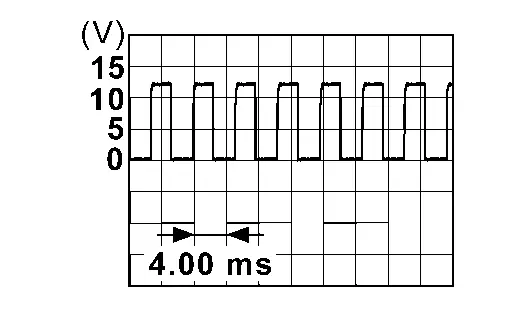
CHECK ENCODER INPUT SIGNAL
Check signal between automatic back door control unit harness connector and ground using oscilloscope.
| (+) | (–) | Condition |
Signal (Reference value) | ||
|---|---|---|---|---|---|
| Automatic back door control unit | |||||
| Connector | Terminal | ||||
| B55 | 29 | Ground | Back door | Moving (auto) |
|
| When stopped | 0 – 1 V or 9 – 16 V | ||||
| 30 | Moving (auto) |
|
|||
| When stopped | 0 – 1 V or 9 – 16 V | ||||


Is the inspection result normal?
YES>>GOT TO 3.
NO>>GO TO 6.
CHECK CONNECTOR
-
Ignition switch OFF.
-
Check the automatic back door control unit harness connector for disconnection or looseness.
-
Check the spindle unit LH harness connector for disconnection or looseness.
Is the inspection result normal?
YES>>GO TO 3.
NO>>Repair/replace harness or connector, securely lock the connector, and GO TO 5.
CHECK AUTOMATIC BACK DOOR CONTROL UNIT POWER SUPPLY AND GROUND CIRCUIT
Check the automatic back door control unit power supply and ground circuits. Refer to Diagnosis Procedure.
Is the inspection result normal?
YES>>GO TO 4.
NO>>Repair/replace harness, connector, fuse, or fusible link, and GO TO 5.
CHECK TERMINAL
-
Ignition switch OFF.
-
Disconnect automatic back door control unit harness connector and then check the automatic back door control unit pin terminals for damage or loose connection with harness connector.
-
Disconnect spindle unit LH harness connector and check spindle unit LH pin terminal for damage or loose connection with harness connector.
Is the inspection result normal?
YES>>Replace automatic back door control unit. Refer to Removal and Installation.
NO>>Repair/replace harness, connector, or terminal.
CHECK ENCODER CIRCUIT
-
Ignition switch OFF.
-
Disconnect automatic back door control unit connector and spindle unit LH connector.
-
Check continuity between automatic back door control unit harness connector and spindle unit LH harness connector.
Automatic back door control unit Spindle unit LH Continuity Connector Terminal Connector Terminal B55 29 B70 5 Yes 30 3 -
Check continuity between automatic back door control unit harness connector and ground.
Automatic back door control unit (-) Continuity Connector Terminal B55 29 Ground No 30
Is the inspection result normal?
YES>>Replace spindle unit LH. Refer to Removal and Installation.
NO>>Repair or replace harness.
B2426-11 Spindle Sensor Lh Nissan Pathfinder 2026
DTC Description
DTC DETECTION LOGIC
| DTC No. |
CONSULT screen items (Trouble diagnosis content) | DTC Detection Condition | |
|---|---|---|---|
| B2426-11 |
Spindle sensor LH (Spindle sensor left hand) |
Diagnosis condition | When automatic back door open/close function operate |
| Signal (terminal) | Encoder LH signal | ||
| Threshold | Automatic back door control unit cannot detect the encoder LH signal | ||
| Diagnosis delay time | 1 second or less | ||
POSSIBLE CAUSE
-
Spindle unit LH
-
Automatic back door control unit
-
Harness or connector (encoder LH circuit is open or shorted)
FAIL-SAFE
Inhibit automatic back door system (only operate back door closure function)
DTC CONFIRMATION PROCEDURE
PERFORM DTC CONFIRMATION PROCEDURE
 CONSULT
-
Ignition switch ON.
-
Operate automatic back door.
-
Check “Self Diagnostic Result” mode of “AUTO BACK DOOR”.
Is DTC detected?
YES>>Refer to DTC Diagnosis Procedure.
NO>>To check malfunction symptom before repair: Refer to Intermittent Incident.
NO>>Confirmation after repair: Inspection End.
DTC Diagnosis Procedure
CHECK ENCODER SIGNAL
 CONSULT
-
Ignition switch ON.
-
Select “AUTO BACK DOOR”.
-
Select “Spindle sensor LH” in “DATA MONITOR” mode.
-
Check that the function operates normally according to the following conditions.
Monitor item Condition Status Spindle sensor LH Back door Open The numeral value increases Close The numeral value decreases
Is the inspection result normal?
YES>>Check intermittent incident. Refer to Intermittent Incident.
NO>>GO TO 2.
CHECK ENCODER POWER SUPPLY
-
Ignition switch OFF.
-
Disconnect spindle unit LH connector.
-
Check voltage between spindle unit LH harness connector and ground.
(+) (–) Voltage
(Approx.)Spindle unit LH Connector Terminal B70 4 Ground Battery voltage
Is the inspection result normal?
YES>>GO TO 7.
NO>>GO TO 3.
CHECK ENCODER CIRCUIT-1
-
Disconnect automatic back door control unit connector.
-
Check continuity between automatic back door control unit harness connector and spindle unit LH harness connector.
Automatic back door control unit Spindle unit LH Continuity Connector Terminal Connector Terminal B55 31 B70 4 Yes -
Check continuity between automatic back door control unit harness connector and ground.
Automatic back door control unit (-) Continuity Connector Terminal B55 31 Ground No
Is the inspection result normal?
YES>>GO TO 4.
NO>>Repair or replace harness.
CHECK CONNECTOR
-
Ignition switch OFF.
-
Check the automatic back door control unit harness connector for disconnection or looseness.
-
Check the spindle unit LH harness connector for disconnection or looseness.
Is the inspection result normal?
YES>>GO TO 5.
NO>>Repair/replace harness.
CHECK AUTOMATIC BACK DOOR CONTROL UNIT POWER SUPPLY AND GROUND CIRCUIT
Check the automatic back door control unit power supply and ground circuits. Refer to Diagnosis Procedure.
Is the inspection result normal?
YES>>GO TO 4.
NO>>Repair/replace harness, connector, fuse, or fusible link, and GO TO 5.
CHECK TERMINAL
-
Ignition switch OFF.
-
Disconnect automatic back door control unit harness connector and then check the automatic back door control unit pin terminals for damage or loose connection with harness connector.
-
Disconnect spindle unit LH harness connector and check spindle unit LH pin terminal for damage or loose connection with harness connector.
Is the inspection result normal?
YES>>Replace automatic back door control unit. Refer to Removal and Installation.
NO>>Repair/replace harness, connector, or terminal.
CHECK ENCODER CIRCUIT-2
-
Disconnect automatic back door control unit connector and spindle unit RH connector.
-
Check continuity between automatic back door control unit harness connector and spindle unit LH harness connector.
Automatic back door control unit Spindle unit LH Continuity Connector Terminal Connector Terminal B55 28 B70 2 Yes -
Check continuity between automatic back door control unit harness connector and ground.
Automatic back door control unit (-) Continuity Connector Terminal B55 28 Ground No
Is the inspection result normal?
YES>>Replace spindle unit LH. Refer to Removal and Installation.
NO>>Repair or replace harness.
B2426-12 Spindle Sensor Lh Nissan Pathfinder 2026
DTC Description
DTC DETECTION LOGIC
| DTC No. |
CONSULT screen items (Trouble diagnosis content) | DTC Detection Condition | |
|---|---|---|---|
| B2426-12 |
Spindle sensor LH (Spindle sensor left hand) |
Diagnosis condition | When the door unlock operates while ignition switch is OFF (auto ACC OFF status) or the battery terminal is removed |
| Signal (terminal) | Encoder LH signal | ||
| Threshold | When automatic back door control unit detect power short of encoder LH circuit | ||
| Diagnosis delay time | 1 second or less | ||
POSSIBLE CAUSE
-
Spindle unit LH
-
Automatic back door control unit
-
Harness or connector (encoder LH circuit is power short)
FAIL-SAFE
Inhibit automatic back door system (only operate back door closure function)
DTC CONFIRMATION PROCEDURE
PERFORM DTC CONFIRMATION PROCEDURE
 CONSULT
-
When the door unlock operates by Intelligent Key or door request switch while ignition switch is OFF (auto ACC OFF status).
-
Check “Self Diagnostic Result” mode of “AUTO BACK DOOR”.
Is DTC detected?
YES>>Refer to DTC Diagnosis Procedure.
NO>>To check malfunction symptom before repair: Refer to Intermittent Incident.
NO>>Confirmation after repair: Inspection End.
DTC Diagnosis Procedure
CHECK ENCODER SIGNAL
 CONSULT
-
Ignition switch ON.
-
Select “AUTO BACK DOOR”.
-
Select “Spindle sensor LH” in “DATA MONITOR” mode.
-
Check that the function operates normally according to the following conditions.
Monitor item Condition Status Spindle sensor LH Back door Open The numeral value increases Close The numeral value decreases
Is the inspection result normal?
YES>>Check intermittent incident. Refer to Intermittent Incident.
NO>>GO TO 2.
CHECK ENCODER CIRCUIT
-
Disconnect automatic back door control unit connector, spindle unit LH connector and spindle unit RH connector.
-
Check voltage between automatic back door control unit harness connector and ground.
Automatic back door control unit — Voltage
(Approx.)Connector Terminal B55 28 Ground 0 V 31
Is the inspection result normal?
YES>>GO TO 3.
NO>>Repair or replace harness.
REPLACE SPINDLE UNIT LH
Replace spindle unit LH. Refer to Removal and Installation.
Is the inspection result normal?
YES>>Inspection End.
NO>>Replace automatic back door control unit. Refer to Removal and Installation.
B2426-13 Spindle Sensor Lh Nissan Pathfinder SUV
DTC Description
DTC DETECTION LOGIC
| DTC No. |
CONSULT screen items (Trouble diagnosis content) | DTC Detection Condition | |
|---|---|---|---|
| B2426-13 |
Spindle sensor LH (Spindle sensor left hand) |
Diagnosis condition | When automatic back door open/close function operate |
| Signal (terminal) | Encoder LH signal | ||
| Threshold | Automatic back door control unit cannot detect the encoder LH signal | ||
| Diagnosis delay time | 1 second or less | ||
POSSIBLE CAUSE
-
Spindle unit LH
-
Automatic back door control unit
-
Harness or connector (encoder LH circuit is open)
FAIL-SAFE
Inhibit automatic back door system (only operate back door closure function)
DTC CONFIRMATION PROCEDURE
PERFORM DTC CONFIRMATION PROCEDURE
 CONSULT
-
Ignition switch ON.
-
Operate automatic back door.
-
Check “Self Diagnostic Result” mode of “AUTO BACK DOOR”.
Is DTC detected?
YES>>Refer to DTC Diagnosis Procedure.
NO>>To check malfunction symptom before repair: Refer to Intermittent Incident.
NO>>Confirmation after repair: Inspection End.
DTC Diagnosis Procedure
CHECK ENCODER SIGNAL
 CONSULT
-
Ignition switch ON.
-
Select “AUTO BACK DOOR”.
-
Select “Spindle sensor LH” in “DATA MONITOR” mode.
-
Check that the function operates normally according to the following conditions.
Monitor item Condition Status Spindle sensor LH Back door Open The numeral value increases Close The numeral value decreases
Is the inspection result normal?
YES>>Check intermittent incident. Refer to Intermittent Incident.
NO>>GO TO 2.
CHECK ENCODER INPUT SIGNAL
Check signal between automatic back door control unit harness connector and ground using oscilloscope.
| (+) | (–) | Condition |
Signal (Reference value) | ||
|---|---|---|---|---|---|
| Automatic back door control unit | |||||
| Connector | Terminal | ||||
| B55 | 29 | Ground | Back door | Moving (auto) |
|
| When stopped | 0 – 1 V or 9 – 16 V | ||||
| 30 | Moving (auto) |
|
|||
| When stopped | 0 – 1 V or 9 – 16 V | ||||


Is the inspection result normal?
YES>>GO TO 4.
NO>>GO TO 3.
CHECK ENCODER CIRCUIT
-
Ignition switch OFF.
-
Disconnect automatic back door control unit connector and spindle unit LH connector.
-
Check continuity between automatic back door control unit harness connector and spindle unit LH harness connector.
Automatic back door control unit Spindle unit LH Continuity Connector Terminal Connector Terminal B55 29 B70 5 Yes 30 3 -
Check continuity between automatic back door control unit harness connector and ground.
Automatic back door control unit — Continuity Connector Terminal B55 29 Ground No 30
Is the inspection result normal?
YES>>Replace spindle unit LH. Refer to Removal and Installation.
NO>>Repair or replace harness.
CHECK ENCODER POWER SUPPLY
-
Ignition switch OFF.
-
Disconnect spindle unit LH connector.
-
Check voltage between spindle unit LH harness connector and ground.
(+) (–) Voltage
(Approx.)Spindle unit LH Connector Terminal B70 4 Ground Battery voltage
Is the inspection result normal?
YES>>GO TO 6.
NO>>GO TO 5.
CHECK ENCODER CIRCUIT-1
-
Disconnect automatic back door control unit connector.
-
Check continuity between automatic back door control unit harness connector and spindle unit LH harness connector.
Automatic back door control unit Spindle unit LH Continuity Connector Terminal Connector Terminal B55 31 B70 4 Yes -
Check continuity between automatic back door control unit harness connector and ground.
Automatic back door control unit — Continuity Connector Terminal B55 31 Ground No
Is the inspection result normal?
YES>>Replace automatic back door control unit. Refer to Removal and Installation.
NO>>Repair or replace harness.
CHECK ENCODER CIRCUIT-2
-
Disconnect automatic back door control unit connector.
-
Check continuity between automatic back door control unit harness connector and spindle unit LH harness connector.
Automatic back door control unit Spindle unit LH Continuity Connector Terminal Connector Terminal B55 28 B70 2 Yes -
Check continuity between automatic back door control unit harness connector and ground.
Automatic back door control unit — Continuity Connector Terminal B55 28 Ground No
Is the inspection result normal?
YES>>Replace spindle unit LH. Refer to Removal and Installation.
NO>>Repair or replace harness.
B2426-25 Spindle Sensor Lh Nissan Pathfinder 5th Gen
DTC Description
DTC DETECTION LOGIC
| DTC No. |
CONSULT screen items (Trouble diagnosis content) | DTC Detection Condition | |
|---|---|---|---|
| B2426-25 |
Spindle sensor LH (Spindle sensor left hand) |
Diagnosis condition | When automatic back door open/close function operate |
| Signal (terminal) | Encoder LH signal | ||
| Threshold | Automatic back door control unit cannot detect the encoder LH signal | ||
| Diagnosis delay time | Less than 40 pulse | ||
POSSIBLE CAUSE
-
Spindle unit LH
-
Automatic back door control unit
-
Harness or connector (encoder LH circuit is open or shorted)
FAIL-SAFE
Inhibit automatic back door system (only operate back door closure function)
DTC CONFIRMATION PROCEDURE
PERFORM DTC CONFIRMATION PROCEDURE
 CONSULT
-
Ignition switch ON.
-
Operate automatic back door.
-
Check “Self Diagnostic Result” mode of “AUTO BACK DOOR”.
Is DTC detected?
YES>>Refer to DTC Diagnosis Procedure.
NO>>To check malfunction symptom before repair: Refer to Intermittent Incident.
NO>>Confirmation after repair: Inspection End.
DTC Diagnosis Procedure
CHECK ENCODER SIGNAL
 CONSULT
-
Ignition switch ON.
-
Select “AUTO BACK DOOR”.
-
Select “Spindle sensor LH” in “DATA MONITOR” mode.
-
Check that the function operates normally according to the following conditions.
Monitor item Condition Status Spindle sensor LH Back door Open The numeral value increases Close The numeral value decreases
Is the inspection result normal?
YES>>Check intermittent incident. Refer to Intermittent Incident.
NO>>GO TO 2.
CHECK ENCODER INPUT SIGNAL
Check signal between automatic back door control unit harness connector and ground using oscilloscope.
| (+) | (–) | Condition |
Signal (Reference value) | ||
|---|---|---|---|---|---|
| Automatic back door control unit | |||||
| Connector | Terminal | ||||
| B55 | 29 | Ground | Back door | Moving (auto) |
|
| When stopped | 0 – 1 V or 9 – 16 V | ||||
| 30 | Moving (auto) |
|
|||
| When stopped | 0 – 1 V or 9 – 16 V | ||||

Is the inspection result normal?
YES>>Replace automatic back door control unit. Refer to Removal and Installation.
NO>>GO TO 3.
CHECK ENCODER CIRCUIT
-
Ignition switch OFF.
-
Disconnect automatic back door control unit connector and spindle unit LH connector.
-
Check continuity between automatic back door control unit harness connector and spindle unit LH harness connector.
Automatic back door control unit Spindle unit LH Continuity Connector Terminal Connector Terminal B55 29 B70 5 Yes 30 3 -
Check continuity between automatic back door control unit harness connector and ground.
Automatic back door control unit (-) Continuity Connector Terminal B55 29 Ground No 30
Is the inspection result normal?
YES>>Replace spindle unit LH. Refer to Removal and Installation.
NO>>Repair or replace harness.
B2428-44 Automatic Back Door Control Unit Nissan Pathfinder SUV
DTC Description
DTC DETECTION LOGIC
| DTC No. |
CONSULT screen items (Trouble diagnosis content) | DTC Detection Condition | |
|---|---|---|---|
| B2428-44 |
Automatic back door control unit (Automatic back door control unit) |
Diagnosis condition | All times |
| Signal (terminal) | — | ||
| Threshold | Automatic back door control unit internal malfunction (data memory error) | ||
| Diagnosis delay time | — | ||
POSSIBLE CAUSE
Automatic back door control unit
FAIL-SAFE
Inhibit automatic back door system all function
DTC CONFIRMATION PROCEDURE
PERFORM DTC CONFIRMATION PROCEDURE
 CONSULT
-
Ignition switch ON.
-
Check “Self Diagnostic Result” mode of “AUTO BACK DOOR”.
Is DTC detected?
YES>>Refer to DTC Diagnosis Procedure.
NO>>To check malfunction symptom before repair: Refer to Intermittent Incident.
NO>>Confirmation after repair: Inspection End.
DTC Diagnosis Procedure
REPLACE AUTOMATIC BACK DOOR CONTROL UNIT
When DTC B2428-44 is detected, replace automatic back door control unit.
>>
Replace automatic back door control unit. Refer to Removal and Installation.
B2428-52 Automatic Back Door Control Unit Nissan Pathfinder 5th Gen
DTC Description
DTC DETECTION LOGIC
| DTC No. |
CONSULT screen items (Trouble diagnosis content) | DTC Detection Condition | |
|---|---|---|---|
| B2428-52 |
Automatic back door control unit (Automatic back door control unit) |
Diagnosis condition | All times |
| Signal (terminal) | — | ||
| Threshold | Automatic back door control unit internal malfunction (program error) | ||
| Diagnosis delay time | 1 second or less | ||
POSSIBLE CAUSE
Automatic back door control unit
FAIL-SAFE
Inhibit automatic back door system all function
DTC CONFIRMATION PROCEDURE
PERFORM DTC CONFIRMATION PROCEDURE
 CONSULT
-
Ignition switch ON.
-
Check “Self Diagnostic Result” mode of “AUTO BACK DOOR”.
Is DTC detected?
YES>>Refer to DTC Diagnosis Procedure.
NO>>To check malfunction symptom before repair: Refer to Intermittent Incident.
NO>>Confirmation after repair: Inspection End.
DTC Diagnosis Procedure
CHECK CONNECTOR
-
Ignition switch OFF.
-
Check the automatic back door control unit harness connector for disconnection or looseness.
Is the inspection result normal?
YES>>GO TO 2.
NO>>Repair/replace harness or connector, securely lock the connector.
CHECK AUTOMATIC BACK DOOR CONTROL UNIT POWER SUPPLY AND GROUND CIRCUIT
Check the automatic back door control unit power supply and ground circuits. Refer to Diagnosis Procedure.
Is the inspection result normal?
YES>>GO TO 3.
NO>>Repair/replace harness, connector, fuse, or fusible link.
CHECK TERMINAL
-
Ignition switch OFF.
-
Disconnect automatic back door control unit harness connector and then check the automatic back door control unit pin terminals for damage or loose connection with harness connector.
Is the inspection result normal?
YES>>Replace automatic back door control unit. Refer to Removal and Installation.
NO>>Repair/replace harness, connector, or terminal.
B2428-54 Automatic Back Door Control Unit Nissan Pathfinder 2022
DTC Description
DTC DETECTION LOGIC
| DTC No. |
CONSULT screen items (Trouble diagnosis content) | DTC Detection Condition | |
|---|---|---|---|
| B2428-54 |
Automatic back door control unit (Automatic back door control unit) |
Diagnosis condition | All times |
| Signal (terminal) | — | ||
| Threshold | When the calibration of [CALIBRATION OF AUTOMATIC BACK DOOR POSITION INFORMATION] is not complete | ||
| Diagnosis delay time | 1 second or less | ||
POSSIBLE CAUSE
[CALIBRATION OF AUTOMATIC BACK DOOR POSITION INFORMATION]: not complete
FAIL-SAFE
Inhibit automatic back door system all function
DTC CONFIRMATION PROCEDURE
PERFORM DTC CONFIRMATION PROCEDURE
 CONSULT
-
Ignition switch ON.
-
Check “Self Diagnostic Result” mode of “AUTO BACK DOOR”.
Is DTC detected?
YES>>Refer to DTC Diagnosis Procedure.
NO>>To check malfunction symptom before repair: Refer to Intermittent Incident.
NO>>Confirmation after repair: Inspection End.
DTC Diagnosis Procedure
CALIBRATION OF AUTOMATIC BACK DOOR POSITION INFORMATION
-
Perform initialization setting of automatic back door position information. Refer to Work Procedure.
-
Erase DTC, and then repeat “DTC CONFIRMATION PROCEDURE”. Refer to DTC Description.
Is DTC detected?
YES>>GO TO 2.
NO>>Inspection End.
CHECK CONNECTOR
-
Ignition switch OFF.
-
Check the automatic back door control unit harness connector for disconnection or looseness.
Is the inspection result normal?
YES>>GO TO 3.
NO>>Repair/replace harness or connector, securely lock the connector..
CHECK AUTOMATIC BACK DOOR CONTROL UNIT POWER SUPPLY AND GROUND CIRCUIT
Check the automatic back door control unit power supply and ground circuits. Refer to Diagnosis Procedure.
Is the inspection result normal?
YES>>GO TO 4.
NO>>Repair/replace harness, connector, fuse, or fusible link..
CHECK TERMINAL
-
Ignition switch OFF.
-
Disconnect automatic back door control unit harness connector and then check the automatic back door control unit pin terminals for damage or loose connection with harness connector.
Is the inspection result normal?
YES>>Replace automatic back door control unit. Refer to Removal and Installation.
NO>>Repair/replace harness, connector, or terminal.

Nissan Pathfinder (R53) 2022-2026 Service Manual
Dtc/circuit Diagnosis (B2419-12 Open Switch ... B2428-54 Automatic Back Door Control Unit)
- B2419-12 Open Switch
- B2419-14 Open Switch
- B2422-78 Back Door Position Abnormal
- B2426-11 Spindle Sensor Lh
- B2426-12 Spindle Sensor Lh
- B2426-13 Spindle Sensor Lh
- B2426-25 Spindle Sensor Lh
- B2428-44 Automatic Back Door Control Unit
- B2428-52 Automatic Back Door Control Unit
- B2428-54 Automatic Back Door Control Unit
Contact Us
Nissan Pathfinder Info Center
Email: info@nipathfinder.com
Phone: +1 (800) 123-4567
Address: 123 Pathfinder Blvd, Nashville, TN 37214, USA
Working Hours: Mon–Fri, 9:00 AM – 5:00 PM (EST)
