Nissan Pathfinder: Dtc/circuit Diagnosis (B2001-45 Intelligent Key Unit ... B2417-15 Touch Sensor Circuit Lh Open)
- B2001-45 Intelligent Key Unit
- B2010-1c Battery Voltage
- B203c-14 Inside Antenna
- B203e-14 Outside Antenna
- B2046-42 Eeprom
- B2087 One Touch Sensor (fl)
- B2086-23: Request Sw (bd/tr)
- B2409-12 Half Latch Switch
- B2409-14 Half Latch Switch
- B2417-15 Touch Sensor Circuit Lh Open
B2001-45 Intelligent Key Unit Nissan Pathfinder 5th Gen
DTC Description
DTC DETECTION LOGIC
| DTC No. |
CONSULT screen items (Trouble diagnosis content) | DTC Detection Condition | |
|---|---|---|---|
| B2001-45 |
Intelligent Key unit (Intelligent Key unit) |
Diagnosis condition | Ignition switch ON |
| Signal (terminal) | — | ||
| Threshold | Intelligent Key unit is internal malfunctioning | ||
| Diagnosis delay time | 1 second or less | ||
POSSIBLE CAUSE
Intelligent Key unit
FAIL-SAFE
—
DTC CONFIRMATION PROCEDURE
DTC CONFIRMATION
 CONSULT
-
Erase DTC.
-
Ignition switch OFF.
-
Ignition switch ON.
-
Check “Self Diagnostic Result” mode of “HANDS FREE MODULE”.
Is DTC detected?
YES>>Refer to DTC Diagnosis Procedure.
NO>>To check malfunction symptom before repair: Refer to Intermittent Incident.
NO>>Confirmation after repair: Inspection End.
DTC Diagnosis Procedure
REPLACE INTELLIGENT KEY UNIT
When DTC “B2001-45” is detected, replace Intelligent Key unit.
>>
Replace Intelligent Key unit. Refer to Removal and Installation.
B2010-1c Battery Voltage Nissan Pathfinder Fifth generation
DTC Description
DTC DETECTION LOGIC
| DTC No. |
CONSULT screen items (Trouble diagnosis content) | DTC Detection Condition | |
|---|---|---|---|
| B2010-1C |
Battery voltage (Battery voltage) |
Diagnosis condition | All times |
| Signal (terminal) | Intelligent Key unit battery power supply signal | ||
| Threshold | Less than 4 V or more than 16 V | ||
| Diagnosis delay time | — | ||
POSSIBLE CAUSE
-
Harness or connector (power supply circuit)
-
Intelligent Key unit
-
Battery
FAIL-SAFE
—
DTC CONFIRMATION PROCEDURE
DTC CONFIRMATION
 CONSULT
-
Erase DTC.
-
Ignition switch OFF.
-
Ignition switch ON.
-
Check “Self Diagnostic Result” mode of “HANDS FREE MODULE”.
Is DTC detected?
YES>>Refer to DTC Diagnosis Procedure.
NO>>To check malfunction symptom before repair: Refer to Intermittent Incident.
NO>>Confirmation after repair: Inspection End.
DTC Diagnosis Procedure
CHECK BATTERY VOLTAGE
Measure the battery voltage. Refer to How to Handle Battery.
Is the inspection result normal?
YES>>GO TO 2.
NO>>Replace battery.
CHECK POWER SUPPLY CIRCUIT
Check Intelligent Key unit power supply circuit. Refer to Diagnosis Procedure.
Is the inspection result normal?
YES>>Replace Intelligent Key unit. Refer to Removal and Installation.
NO>>Repair the malfunctioning part.
B203c-14 Inside Antenna Nissan Pathfinder 5th Gen
DTC Description
DTC DETECTION LOGIC
| DTC No. |
CONSULT screen items (Trouble diagnosis content) | DTC detecting condition | |
|---|---|---|---|
| B203C-14 |
Inside antenna (Inside antenna) |
Diagnosis condition | Work support “INSIDE/OUTSIDE ANT DIAGNOSIS”: activated |
| Signal (terminal) | Inside key antenna (console) signal (Intelligent Key unit connector terminal: 33, 34) | ||
| Threshold | Inside key antenna (console) circuit is shorted to ground | ||
| Diagnosis delay time | 1 second or less | ||
POSSIBLE CAUSE
-
Intelligent Key unit
-
Inside key antenna (console)
-
Harness or connector (inside key antenna (console) circuit is open or shorted)
FAIL-SAFE
–
DTC CONFIRMATION PROCEDURE
PERFORM DTC CONFIRMATION PROCEDURE
 CONSULT
-
Select “INSIDE/OUTSIDE ANT DIAGNOSIS” in “WORK SUPPORT” mode of “HANDS FREE MODULE”.
-
Check the “Self Diagnosis Result” mode of “HANDS FREE MODULE”.
Is DTC detected?
YES>>Refer to DTC Diagnosis Procedure.
NO>>To check malfunction symptom before repair: Refer to Intermittent Incident.
NO>>Confirmation after repair: Inspection End.
DTC Diagnosis Procedure
CHECK INSIDE KEY ANTENNA (CONSOLE) INPUT SIGNAL 1
-
Ignition switch ON.
-
Check signal between Intelligent Key unit harness connector and ground using oscilloscope.
(+) (–) Condition Signal
(Reference value)Intelligent Key unit Connector Terminal M38 33 Ground Press push-button ignition switch When Intelligent Key is in the passenger compartment 
When Intelligent Key is not in the passenger compartment 
34 When Intelligent Key is in the passenger compartment 
When Intelligent Key is not in the passenger compartment 
Is the inspection result normal?
YES>>Replace Intelligent Key unit. Refer to Removal and Installation.
NO>>GO TO 2.
CHECK INSIDE KEY ANTENNA (CONSOLE) CIRCUIT
-
Ignition switch OFF.
-
Disconnect Intelligent Key unit connector and inside key antenna (console) connector.
-
Check continuity between Intelligent Key unit harness connector and inside key antenna (console) harness connector.
Intelligent Key unit Inside key antenna (console) Continuity Connector Terminal Connector Terminal M38 33 M147 2 Yes 34 1 -
Check continuity between Intelligent Key unit harness connector and ground.
Intelligent Key unit (-) Continuity Connector Terminal M38 33 Ground No 34
Is the inspection result normal?
YES>>GO TO 3.
NO>>Repair or replace harness.
CHECK INSIDE KEY ANTENNA (CONSOLE) INPUT SIGNAL 2
-
Replace inside key antenna (console). (New antenna or other antenna)
-
Connect Intelligent Key unit connector and inside key antenna connector.
-
Ignition switch ON.
-
Check signal between Intelligent Key unit harness connector and ground using oscilloscope.
(+) (–) Condition Signal
(Reference value)Intelligent Key unit Connector Terminal M38 33 Ground Press push-button ignition switch When Intelligent Key is in the passenger compartment 
When Intelligent Key is not in the passenger compartment 
34 When Intelligent Key is in the passenger compartment 
When Intelligent Key is not in the passenger compartment 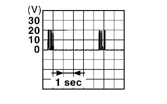
Is the inspection result normal?
YES>>Replace inside key antenna (console). Refer to Removal and Installation.
NO>>Replace Intelligent Key unit. Refer to Removal and Installation.
B203e-14 Outside Antenna Nissan Pathfinder R53
DTC Description
DTC DETECTION LOGIC
| DTC No. |
CONSULT screen items (Trouble diagnosis content) | DTC detecting condition | |
|---|---|---|---|
| B203E-14 |
Outside antenna (Outside antenna) |
Diagnosis condition | Work support “INSIDE/OUTSIDE ANT DIAGNOSIS”: activated |
| Signal (terminal) | Outside key antenna (rear door LH) signal (Intelligent Key unit connector terminal: 35, 36) | ||
| Threshold | Outside key antenna (rear door LH) circuit is shorted to ground | ||
| Diagnosis delay time | 1 second or less | ||
POSSIBLE CAUSE
-
Intelligent Key unit
-
Outside key antenna (rear door LH)
-
Harness or connector [outside key antenna (rear door LH) circuit is open or shorted]
FAIL-SAFE
–
DTC CONFIRMATION PROCEDURE
PERFORM DTC CONFIRMATION PROCEDURE
 CONSULT
-
Select “INSIDE/OUTSIDE ANT DIAGNOSIS” in “WORK SUPPORT” mode of “HANDS FREE MODULE”.
-
Check “Self Diagnosis Result” mode of “HANDS FREE MODULE”.
Is DTC detected?
YES>>Refer to DTC Diagnosis Procedure.
NO>>To check malfunction symptom before repair: Refer to Intermittent Incident.
NO>>Confirmation after repair: Inspection End.
DTC Diagnosis Procedure
CHECK OUTSIDE KEY ANTENNA (REAR DOOR LH) INPUT SIGNAL 1
-
Ignition switch ON.
-
Check signal between Intelligent Key unit harness connector and ground using oscilloscope.
(+) (–) Condition Signal
(Reference value)Intelligent Key unit Connector Terminal M38 35 Ground When the door request switch (front door LH or rear door LH) is operated with ignition switch ON When Intelligent Key is in the antenna detection area 
When Intelligent Key is not in the antenna detection area 
36 When Intelligent Key is in the antenna detection area 
When Intelligent Key is not in the antenna detection area 
Is the inspection result normal?
YES>>Replace Intelligent Key unit. Refer to Removal and Installation.
NO>>GO TO 2.
CHECK OUTSIDE KEY ANTENNA (REAR DOOR LH) CIRCUIT
-
Ignition switch OFF.
-
Disconnect Intelligent Key unit connector and outside key antenna (rear door LH) connector.
-
Check continuity between Intelligent Key unit harness connector and outside key antenna (rear door LH) connector.
Intelligent Key unit Outside key antenna (rear door LH) Continuity Connector Terminal Connector Terminal M38 35 D203 2 Yes 36 1 -
Check continuity between Intelligent Key unit harness connector and ground.
Intelligent Key unit (-) Continuity Connector Terminal M38 35 Ground No 36
Is the inspection result normal?
YES>>GO TO 3.
NO>>Repair or replace harness.
CHECK OUTSIDE KEY ANTENNA (REAR DOOR LH) INPUT SIGNAL 2
-
Replace outside key antenna (rear door LH). (New antenna or other antenna)
-
Connect Intelligent Key unit connector and outside key antenna (rear door LH) connector.
-
Ignition switch ON.
-
Check signal between Intelligent Key unit harness connector and ground using oscilloscope.
(+) (–) Condition Signal
(Reference value)Intelligent Key unit Connector Terminal M38 35 Ground When the door request switch (front door LH or rear door LH) is operated with ignition switch ON When Intelligent Key is in the antenna detection area 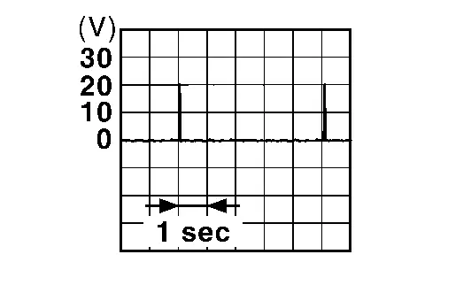
When Intelligent Key is not in the antenna detection area 
36 When Intelligent Key is in the antenna detection area 
When Intelligent Key is not in the antenna detection area 
Is the inspection result normal?
YES>>Replace outside key antenna (rear door LH). Refer to Removal and Installation.
NO>>Replace Intelligent Key unit. Refer to Removal and Installation.
B2046-42 Eeprom Nissan Pathfinder SUV
DTC Description
DTC DETECTION LOGIC
| DTC No. |
CONSULT screen items (Trouble diagnosis content) | DTC Detection Condition | |
|---|---|---|---|
| B2046-42 |
EEPROM (Electrically Erasable Programmable Read-Only Memory) |
Diagnosis condition | Ignition switch ON |
| Signal (terminal) | — | ||
| Threshold | EEPROM in Intelligent Key unit is malfunctioning | ||
| Diagnosis delay time | 1 second or less | ||
POSSIBLE CAUSE
-
Intelligent Key unit
-
Mistook the "Re programming"
FAIL-SAFE
—
DTC CONFIRMATION PROCEDURE
DTC CONFIRMATION
 CONSULT
-
Erase DTC.
-
Ignition switch OFF.
-
Ignition switch ON.
-
Check “Self Diagnostic Result” mode of “HANDS FREE MODULE”.
Is DTC detected?
YES>>Refer to DTC Diagnosis Procedure.
NO>>To check malfunction symptom before repair: Refer to Intermittent Incident.
NO>>Confirmation after repair: Inspection End.
DTC Diagnosis Procedure
PERFORM "REPROGRAMING"
 CONSULT
-
Perform "Reprograming".
-
Erase DTC.
-
Ignition switch OFF.
-
Ignition switch ON.
-
Check “Self Diagnostic Result” mode of “HANDS FREE MODULE”.
Is DTC detected?
YES>>GO TO 2.
NO>>Inspection End.
REPLACE INTELLIGENT KEY UNIT
Replace Intelligent Key unit. Refer to Removal and Installation.
>>
Inspection End.
B2087 One Touch Sensor (fl) Nissan Pathfinder Fifth generation
DTC Description
DTC DETECTION LOGIC
| DTC No. |
CONSULT screen items (Trouble diagnosis content) | DTC Detection Condition | ||
|---|---|---|---|---|
| B2087-08 |
One touch sensor (FL) [Request switch (front left side)] |
[BUS] | Diagnosis condition | Ignition switch ON |
| Signal (terminal) | Door request switch signal (Intelligent Key unit connector terminal 4) | |||
| Threshold | Intelligent Key unit detects that the front door request switch LH is stuck ON | |||
| Diagnosis delay time | 10 seconds or more | |||
| B2087-11 | [GND-SHORT} | Diagnosis condition | Ignition switch ON | |
| Signal (terminal) | Door request switch signal (Intelligent Key unit connector terminal 4) | |||
| Threshold | Intelligent Key unit detects that the front door request switch LH is stuck ON | |||
| Diagnosis delay time | 10 seconds or more | |||
| B2087-23 | [LOWER LIMIT ERR] | Diagnosis condition | Ignition switch ON | |
| Signal (terminal) | Door request switch signal (Intelligent Key unit connector terminal 4) | |||
| Threshold | Intelligent Key unit detects that the front door request switch LH is stuck ON | |||
| Diagnosis delay time | 10 seconds or more | |||
| B2087-24 | [UPPER LIMIT ERR] | Diagnosis condition | Ignition switch ON | |
| Signal (terminal) | Door request switch signal (Intelligent Key unit connector terminal 4) | |||
| Threshold | Intelligent Key unit detects that the front door request switch LH is stuck ON | |||
| Diagnosis delay time | 10 seconds or more | |||
| B2087-44 | [DATA MEM FAIL] | Diagnosis condition | Ignition switch ON | |
| Signal (terminal) | Door request switch signal (Intelligent Key unit connector terminal 4) | |||
| Threshold | Intelligent Key unit detects that the front door request switch LH is stuck ON | |||
| Diagnosis delay time | 10 seconds or more | |||
POSSIBLE CAUSE
-
Front door request switch LH
-
Harness or connector (front door request switch LH circuit is shorted)
-
Intelligent Key unit
FAIL-SAFE
—
DTC CONFIRMATION PROCEDURE
CHECK SELF-DIAG RESULT
 CONSULT
-
Ignition switch ON and wait for 10 seconds or more.
-
Check “Self Diagnostic Result” mode of “HANDS FREE MODULE”.
Is DTC detected?
YES>>Refer to DTC Diagnosis Procedure.
NO>>To check malfunction symptom before repair: Refer to Intermittent Incident.
NO>>Confirmation after repair: Inspection End.
DTC Diagnosis Procedure
CHECK DOOR REQUEST SWITCH INPUT SIGNAL
-
Ignition switch OFF.
-
Disconnect front door request switch LH connector.
-
Check voltage between front door request switch LH harness connector and ground.
(+) (–) Voltage
(Approx.)Front door request switch LH Connector Terminal D3 1 Ground Battery voltage
Is the inspection result normal?
YES>>GO TO 3.
NO>>GO TO 2.
CHECK DOOR REQUEST SWITCH CIRCUIT
-
Disconnect Intelligent Key unit connector.
-
Check continuity between front door request switch LH harness connector and Intelligent Key unit harness connector.
Front door request switch LH Intelligent Key unit Continuity Connector Terminal Connector Terminal D3 1 M38 4 Yes -
Check continuity between front door request switch LH harness connector and ground.
Front door request switch LH (-) Continuity Connector Terminal D3 1 Ground No
Is the inspection result normal?
YES>>Replace Intelligent Key unit. Refer to Removal and Installation.
NO>>Repair or replace harness.
CHECK DOOR REQUEST SWITCH GROUND CIRCUIT
Check continuity between front door request switch LH harness connector and ground.
| Front door request switch LH | (-) | Continuity | |
|---|---|---|---|
| Connector | Terminal | ||
| D3 | 2 | Ground | Yes |
Is the inspection result normal?
YES>>GO TO 4.
NO>>Repair or replace harness.
CHECK DOOR REQUEST SWITCH
Refer to Component Inspection.
Is the inspection result normal?
YES>>GO TO 5.
NO>>Replace front door outside handle. Refer to Removal and Installation.
CHECK INTERMITTENT INCIDENT
Refer to Intermittent Incident.
>>
Inspection End.
B2086-23: Request Sw (bd/tr) Nissan Pathfinder
DTC Description
DTC DETECTION LOGIC
| DTC No. |
CONSULT screen items (Trouble diagnosis content) | DTC Detection Condition | |
|---|---|---|---|
| B2086-23 |
Request SW (BD/TR) [Request switch (back door/trunk)] |
Diagnosis condition | Ignition switch ON |
| Signal (terminal) | Door request switch signal (Intelligent Key unit connector terminal 5) | ||
| Threshold | Intelligent Key unit detects that the back door request switch is stuck ON | ||
| Diagnosis delay time | 10 seconds or more | ||
POSSIBLE CAUSE
-
Back door opener switch
-
Harness or connector (back door request switch circuit is shorted)
-
Intelligent Key unit
FAIL-SAFE
—
DTC CONFIRMATION PROCEDURE
CHECK SELF-DIAG RESULT
 CONSULT
-
Ignition switch ON and wait for 10 seconds or more.
-
Check “Self Diagnostic Result” mode of “HANDS FREE MODULE”.
Is DTC detected?
YES>>Refer to DTC Diagnosis Procedure.
NO>>To check malfunction symptom before repair: Refer to Intermittent Incident.
NO>>Confirmation after repair: Inspection End.
DTC Diagnosis Procedure
CHECK BACK DOOR REQUEST SWITCH INPUT SIGNAL
-
Ignition switch OFF.
-
Disconnect back door opener switch connector.
-
Check voltage between back door opener switch harness connector and ground.
(+) (–) Voltage
(Approx.)Back door opener switch Connector Terminal D559 4 Ground Battery voltage
Is the inspection result normal?
YES>>GO TO 3.
NO>>GO TO 2.
CHECK BACK DOOR REQUEST SWITCH CIRCUIT
-
Disconnect Intelligent Key unit connector.
-
Check continuity between back door opener switch harness connector and Intelligent Key unit harness connector.
Back door opener switch Intelligent Key unit Continuity Connector Terminal Connector Terminal D559 4 M38 5 Yes -
Check continuity between back door opener switch harness connector and ground.
Back door opener switch — Continuity Connector Terminal D559 4 Ground No
Is the inspection result normal?
YES>>Replace Intelligent Key unit. Refer to Removal and Installation.
NO>>Repair or replace harness.
CHECK BACK DOOR REQUEST SWITCH GROUND CIRCUIT
Check continuity between back door opener switch harness connector and ground.
| Back door opener switch | — | Continuity | |
|---|---|---|---|
| Connector | Terminal | ||
| D559 | 3 | Ground | Yes |
Is the inspection result normal?
YES>>GO TO 4.
NO>>Repair or replace harness.
CHECK BACK DOOR REQUEST SWITCH
Refer to Component Inspection.
Is the inspection result normal?
YES>>GO TO 5.
NO>>Replace back door opener switch. Refer to Removal and Installation.
CHECK INTERMITTENT INCIDENT
Refer to Intermittent Incident.
>>
Inspection End.
B2409-12 Half Latch Switch Nissan Pathfinder R53
DTC Description
DTC DETECTION LOGIC
| DTC No. |
CONSULT screen items (Trouble diagnosis content) | DTC Detection Condition | |
|---|---|---|---|
| B2409-12 |
Half latch switch (Half latch switch) |
Diagnosis condition | When the door unlock operates while ignition switch is OFF (auto ACC OFF status) or the battery terminal is removed |
| Signal (terminal) | Half latch switch signal | ||
| Threshold | Automatic back door control unit detect power short of half latch switch circuit | ||
| Diagnosis delay time | 1 second or less | ||
POSSIBLE CAUSE
-
Harness or connector (half latch switch circuit is power short)
-
Automatic back door control unit
-
Back door lock assembly (half latch switch)
FAIL-SAFE
Inhibit automatic back door system [only operate back door closure function (open function)]
DTC CONFIRMATION PROCEDURE
PERFORM DTC CONFIRMATION PROCEDURE
 CONSULT
-
When the door unlock operates by Intelligent Key or door request switch while ignition switch is OFF (auto ACC OFF status).
-
Check “Self Diagnostic Result” mode of “AUTO BACK DOOR”.
Is DTC detected?
YES>>Refer to DTC Diagnosis Procedure.
NO>>To check malfunction symptom before repair: Refer to Intermittent Incident.
NO>>Confirmation after repair: Inspection End.
DTC Diagnosis Procedure
CHECK HALF LATCH SWITCH INPUT SIGNAL
Check voltage between automatic back door control unit harness connector and ground.
| (+) | (–) | Condition |
Voltage (Approx.) | ||
|---|---|---|---|---|---|
| Automatic back door control unit | |||||
| Connector | Terminal | ||||
| B55 | 10 | Ground | Back door | Open | 0V |
| Fully closed/ half latch | Battery voltage | ||||
Is the inspection result normal?
YES>>Replace automatic back door control unit. Refer to Removal and Installation.
NO>>GO TO 2.
CHECK HALF LATCH SWITCH CIRCUIT
-
Disconnect automatic back door control unit connector and back door lock assembly connector.
-
Check voltage between automatic back door control unit harness connector and ground.
Automatic back door control unit — Voltage Connector Terminal B55 10 Ground 0 V
Is the inspection result normal?
YES>>Replace back door lock assembly. Refer to Removal and Installation.
NO>>Repair or replace harness.
B2409-14 Half Latch Switch Nissan Pathfinder SUV
DTC Description
DTC DETECTION LOGIC
| DTC No. |
CONSULT screen items (Trouble diagnosis content) | DTC Detection Condition | |
|---|---|---|---|
| B2409-14 |
Half latch switch (Half latch switch) |
Diagnosis condition | When back door open |
| Signal (terminal) | Half latch switch signal | ||
| Threshold |
Automatic back door control unit detects when one of the following conditions is satisfied
|
||
| Diagnosis delay time | 1 second or less | ||
POSSIBLE CAUSE
-
Harness or connector (half latch switch circuit is ground short)
-
Automatic back door control unit
-
Back door lock assembly (half latch switch)
FAIL-SAFE
-
Inhibit automatic back door system [only operate back door closure function (open function)]
-
Manual latch and unlatch functions available only
DTC CONFIRMATION PROCEDURE
PERFORM DTC CONFIRMATION PROCEDURE
 CONSULT
-
Ignition switch ON.
-
Operate automatic back door.
-
Check “Self Diagnostic Result” mode of “AUTO BACK DOOR”.
Is DTC detected?
YES>>Refer to DTC Diagnosis Procedure.
NO>>To check malfunction symptom before repair: Refer to Intermittent Incident.
NO>>Confirmation after repair: Inspection End.
DTC Diagnosis Procedure
CHECK HALF LATCH SWITCH INPUT SIGNAL
Check voltage between automatic back door control unit harness connector and ground.
| (+) | (–) | Condition |
Voltage (Approx.) | ||
|---|---|---|---|---|---|
| Automatic back door control unit | |||||
| Connector | Terminal | ||||
| B55 | 10 | Ground | Back door | Open | 0 V |
| Fully closed/ half latch | Battery voltage | ||||
Is the inspection result normal?
YES>>Replace automatic back door control unit. Refer to Removal and Installation.
NO>>GO TO 2.
CHECK HALF LATCH SWITCH CIRCUIT
-
Ignition switch OFF.
-
Disconnect automatic back door control unit connector and back door lock assembly connector.
-
Check continuity between automatic back door control unit harness connector and back door lock assembly harness connector.
Automatic back door control unit Back door lock assembly Continuity Connector Terminal Connector Terminal B55 10 D557 6 Yes -
Check continuity between automatic back door control unit harness connector and ground.
Automatic back door control unit (-) Continuity Connector Terminal B55 10 Ground No
Is the inspection result normal?
YES>>Replace back door lock assembly. Refer to Removal and Installation.
NO>>Repair or replace harness.
B2417-15 Touch Sensor Circuit Lh Open Nissan Pathfinder R53
DTC Description
DTC DETECTION LOGIC
| DTC No. |
CONSULT screen items (Trouble diagnosis content) | DTC Detection Condition | |
|---|---|---|---|
| B2417-15 |
Touch sensor circuit LH open (Touch sensor circuit left hand open) |
Diagnosis condition | All times |
| Signal (terminal) | Touch sensor LH signal | ||
| Threshold |
Automatic back door control unit detects when one of the following conditions is satisfied
|
||
| Diagnosis delay time | 1 second or less | ||
POSSIBLE CAUSE
-
Harness or connector (touch sensor LH circuit is open or shorted)
-
Automatic back door control unit
-
Touch sensor LH
FAIL-SAFE
Inhibit automatic back door system (only operate back door closure function)
DTC CONFIRMATION PROCEDURE
PERFORM DTC CONFIRMATION PROCEDURE
 CONSULT
-
Ignition switch ON.
-
Check “Self Diagnostic Result” mode of “AUTO BACK DOOR”.
Is DTC detected?
YES>>Refer to DTC Diagnosis Procedure.
NO>>To check malfunction symptom before repair: Refer to Intermittent Incident.
NO>>Confirmation after repair: Inspection End.
DTC Diagnosis Procedure
CHECK TOUCH SENSOR LH INPUT SIGNAL
Check voltage between automatic back door control unit harness connector and ground.
| (+) | (–) | Condition |
Voltage (Approx.) | ||
|---|---|---|---|---|---|
| Automatic back door control unit | |||||
| Connector | Terminal | ||||
| B55 | 12 | Ground | Touch sensor LH | Detect obstruction | 0.2 – 3 V |
| Other than above | 3.4 – 6.5 V | ||||
Is the inspection result normal?
YES>>GO TO 2.
NO>>GO TO 5.
CHECK CONNECTOR
-
Ignition switch OFF.
-
Check the automatic back door control unit harness connector for disconnection or looseness.
-
Check the touch sensor LH harness connector for disconnection or looseness.
Is the inspection result normal?
YES>>GO TO 3.
NO>>Repair/replace harness or connector, securely lock the connector, and GO TO 5.
CHECK AUTOMATIC BACK DOOR CONTROL UNIT POWER SUPPLY AND GROUND CIRCUIT
Check the automatic back door control unit power supply and ground circuits. Refer to Diagnosis Procedure.
Is the inspection result normal?
YES>>GO TO 4.
NO>>Repair/replace harness, connector, fuse, or fusible link, and GO TO 5.
CHECK TERMINAL
-
Ignition switch OFF.
-
Disconnect automatic back door control unit harness connector and then check the automatic back door control unit pin terminals for damage or loose connection with harness connector.
-
Disconnect touch sensor LH harness connector and check touch sensor LH pin terminal for damage or loose connection with harness connector.
Is the inspection result normal?
YES>>Replace automatic back door control unit. Refer to Removal and Installation.
NO>>Repair/replace harness, connector, or terminal.
CHECK TOUCH SENSOR LH CIRCUIT
-
Ignition switch OFF.
-
Disconnect automatic back door control unit connector and touch sensor LH connector.
-
Check continuity between automatic back door control unit harness connector and touch sensor LH harness connector.
Automatic back door control unit Touch sensor LH Continuity Connector Terminal Connector Terminal B55 12 D530 1 Yes -
Check continuity between automatic back door control unit harness connector and ground.
Automatic back door control unit (-) Continuity Connector Terminal B55 12 Ground No
Is the inspection result normal?
YES>>GO TO 6.
NO>>Repair or replace harness.
CHECK TOUCH SENSOR LH GROUND CIRCUIT
-
Disconnect touch sensor RH connector.
-
Check continuity between automatic back door control unit harness connector and touch sensor LH harness connector.
Automatic back door control unit Touch sensor LH Continuity Connector Terminal Connector Terminal B55 14 D530 4 Yes -
Check continuity between automatic back door control unit harness connector and ground.
Automatic back door control unit (-) Continuity Connector Terminal B55 14 Ground No
Is the inspection result normal?
YES>>GO TO 7.
NO>>Repair or replace harness.
CHECK TOUCH LH SENSOR
Check touch sensor. Refer to Component Inspection.
Is the inspection result normal?
YES>>Check intermittent incident. Refer to Intermittent Incident.
NO>>Replace touch sensor LH. Refer to Removal and Installation.

Nissan Pathfinder (R53) 2022-2026 Service Manual
Dtc/circuit Diagnosis (B2001-45 Intelligent Key Unit ... B2417-15 Touch Sensor Circuit Lh Open)
- B2001-45 Intelligent Key Unit
- B2010-1c Battery Voltage
- B203c-14 Inside Antenna
- B203e-14 Outside Antenna
- B2046-42 Eeprom
- B2087 One Touch Sensor (fl)
- B2086-23: Request Sw (bd/tr)
- B2409-12 Half Latch Switch
- B2409-14 Half Latch Switch
- B2417-15 Touch Sensor Circuit Lh Open
Contact Us
Nissan Pathfinder Info Center
Email: info@nipathfinder.com
Phone: +1 (800) 123-4567
Address: 123 Pathfinder Blvd, Nashville, TN 37214, USA
Working Hours: Mon–Fri, 9:00 AM – 5:00 PM (EST)
