Nissan Pathfinder: Power Outlet - Wireless Charger
- Precaution. Precaution
- Ecu Diagnosis Information. Wireless Charger Unit
- Symptom Diagnosis. Wireless Charger System Symptoms
Precaution. Precaution Nissan Pathfinder SUV
Precaution for Supplemental Restraint System (SRS) "AIR BAG" and "SEAT BELT PRE-TENSIONER"
The Supplemental Restraint System such as “AIR BAG” and “SEAT BELT PRE-TENSIONER”, used along with a front seat belt, helps to reduce the risk or severity of injury to the driver and front passenger for certain types of collisions.
Information necessary to service the system safely is included in the “SRS AIR BAG” and “SEAT BELT” sections of this Service Manual.
WARNING:
Always observe the following items for preventing accidental activation:
-
To avoid rendering the SRS inoperative, which could increase the risk of personal injury or death in the event of a collision that would result in air bag inflation, it is recommended that all maintenance and repair be performed by an authorized NISSAN/INFINITI dealer.
-
Improper repair, including incorrect removal and installation of the SRS, can lead to personal injury caused by unintentional activation of the system. For removal of Spiral Cable and Air Bag Module, see “SRS AIR BAG”.
-
Never use electrical test equipment on any circuit related to the SRS unless instructed to in this Service Manual. SRS wiring harnesses can be identified by yellow and/or orange harnesses or harness connectors.
PRECAUTIONS WHEN USING POWER TOOLS (AIR OR ELECTRIC) AND HAMMERS
WARNING:
Always observe the following items for preventing accidental activation:
-
When working near the Air Bag Diagnosis Sensor Unit or other Air Bag System sensors with the ignition/power switch ON or engine running, never use air or electric power tools or strike near the sensor(s) with a hammer. Heavy vibration could activate the sensor(s) and deploy the air bag(s), possibly causing serious injury.
-
When using air or electric power tools or hammers, always place the ignition/power switch in the OFF position, disconnect the 12V battery or batteries, and wait at least 3 minutes before performing any service.
Ecu Diagnosis Information. Wireless Charger Unit Nissan Pathfinder R53
Reference Value
VALUES ON THE DIAGNOSIS TOOL
 NOTE:
NOTE:
The following table includes information (items) inapplicable to this Nissan Pathfinder vehicle: For information (items) applicable to this vehicle, refer to CONSULT display items.
| Monitor Item | Condition | Value/Status | |
|---|---|---|---|
| COMPUTER INTERNAL TEMPERATURE | Ignition switch ON | — | Monitors the temperature inside the wireless charger. |
| Object detected | Ignition switch ON | Something is found on the wireless charger. | Yes |
| No objects are found on the wireless charger. | No | ||
| Wireless charger unit is starting up. | Initial | ||
| Wireless charger unit is not receiving a signal. | Inactive | ||
| DETECTED PHONE | Ignition switch ON | A receiver (smartphone etc.) is found on the wireless charger. | Yes |
| No receivers are found on the wireless charger. | No | ||
| Wireless charger unit is starting up. | UNAVAILABLE | ||
| Wireless charger unit is not receiving a signal. | Inactive | ||
| Presence of foreign object(s) | Ignition switch ON | When a foreign object is detected on the wireless charger. | Yes |
| When no foreign objects are detected on the wireless charger. | No | ||
| Wireless charger unit is starting up. | UNAVAILABLE | ||
| Wireless charger unit is not receiving a signal. | Inactive | ||
| Charger power status | Ignition switch ON | When the wireless charger is active. | Yes |
| When the wireless charger is inactive. | No | ||
| Wireless charger unit is starting up. | UNAVAILABLE | ||
| Wireless charger unit is not receiving a signal. | Inactive | ||
| Charging State | Ignition switch ON | No charging | No |
| Low speed charging (Max. 5 W) | Low | ||
| Normal charging (Max. 15 W) | Mid | ||
| Wireless charger unit is starting up. | UNAVAILABLE | ||
| Wireless charger unit is not receiving a signal. | Inactive | ||
| Hardware version | Ignition switch ON | Displays a hardware version. | v1.1 — v2.5 |
| When a hardware version cannot be confirmed. | Unknown | ||
| Wireless charger unit is not receiving a signal. | Inactive | ||
| Receiver IC chip ID | Ignition switch ON | — | Displays ID of IC chip on receiver (smartphone etc.). |
| Receiver IC chip manufacturer | Ignition switch ON | When a manufacturer of receiver is Samsung. | Samsung |
| When a manufacturer of receiver is LGE. | LGE | ||
| When a manufacturer of receiver is Nokia. | Nokia | ||
| When a manufacturer of receiver is Motorola. | motorola | ||
| When a manufacturer of receiver is Apple. | Apple | ||
| When a manufacturer of receiver is except for above. | Others | ||
| When manufacturer of receiver cannot be confirmed. | Unknown | ||
| Receiver Qi version | Ignition switch ON | Displays Qi version of receiver (smartphone etc.). | 1.0/1.1/1.2 |
| When Qi version of receiver (smartphone etc.) is except for 1.0, 1.1 or 1.2. | Other | ||
| When Qi version of receiver (smartphone etc.) is unknown. | Unknown | ||
| When unable to detect any receiver (smartphone etc.). | Inactive | ||
| Voltage of charging coil | Ignition switch ON | — | Displays voltage on charging coil. |
| Current of charging coil | Ignition switch ON | — | Displays electric current of charging coil. |
| Input voltage | Ignition switch ON | — | Displays input voltage to charging coil. |
| Input current of charging coil | Ignition switch ON | — | Displays input electric current to charging coil. |
| Charging power consumption | Ignition switch ON | — | Displays power consumption of wireless charger. |
| Receive power (receiver side) | Ignition switch ON | — | Displays power consumption detected from receiver (smartphone etc.). |
| Power loss (charger - receiver) | Ignition switch ON | — | Displays power loss between wireless charger and receiver. |
| Charging Time | Ignition switch ON | — | Displays charging time. |
| Disconnection of charging coil | Ignition switch ON | The coil in the wireless charger is broken. | Yes |
| The coil in the wireless charger is not broken. | No | ||
| Wireless charger unit is starting up. | UNAVAILABLE | ||
| Wireless charger unit is not receiving a signal. | Inactive | ||
| Memory error | Ignition switch ON | Wireless charger is detecting a memory error. | Yes |
| Wireless charger is detecting no memory error. | No | ||
| Wireless charger unit is starting up. | UNAVAILABLE | ||
| Wireless charger unit is not receiving a signal. | Inactive | ||
| Reason of stop charging | Ignition switch ON | A statue of charging being complete. | Charge complete |
| High temperature error. | Type2 | ||
| Foreign object detection error. | Type4 | ||
| Abnormal high voltage input error. | Type6 | ||
| Charge stop request | Ignition switch ON | When not receiving "charge stop request signal" from Intelligent Key unit. | No |
| When receiving "charge stop request signal" from Intelligent Key unit. | Stop | ||
| Wireless charger unit is not receiving a signal. | Inactive | ||
| YELLOW LED | Ignition switch ON | LED (Orange/Yellow) OFF | Off |
| LED (Orange/Yellow) ON | On | ||
| Wireless charger unit is starting up. | UNAVAILABLE | ||
| Wireless charger unit is not receiving a signal. | Inactive | ||
| LED (green) | Ignition switch ON | LED (Green) OFF | Off |
| LED (Green) ON | On | ||
| Wireless charger unit is starting up. | UNAVAILABLE | ||
| Wireless charger unit is not receiving a signal. | Inactive | ||
| Firmware Version | Ignition switch ON | Displays firmware version. | v1.1 — v2.5 |
| When firmware version is unknown. | Unknown | ||
| When firmware version cannot be detected. | Inactive | ||
TERMINAL LAYOUT
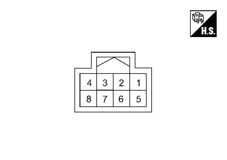
PHYSICAL VALUES
|
Terminal No. (Wire color) | Description | Condition |
Value (Approx.) | |||
|---|---|---|---|---|---|---|
| + | – | Signal name | Input/ Output | |||
|
1 (P) |
Ground | Ignition power supply | Input | Ignition switch ON | Battery voltage | |
|
2 (SB) |
Ground | CAN-High | Input/ Output | Ignition switch ON | — | |
|
4 (B) |
Ground | Ground | — | Ignition switch ON | 0 V | |
|
5 (GR) |
Ground | Wireless charger indicator ground | — | Ignition switch ON | 0 V | |
|
6 (V) |
Ground | CAN-Low | Input/ Output | Ignition switch ON | — | |
|
7 (G) |
5 (GR) |
Wireless charger indicator (green) signal | Output |
|
3.0 V | |
|
0 V | |||||
|
8 (W) |
5 (GR) |
Wireless charger indicator (orange) signal | Output |
|
2.0 V | |
|
0 V | |||||
Fail-safe
|
DTC Display contents of CONSULT | Fail-safe condition |
|---|---|
| B1B00-08 CAN COMMUNICATION | Wireless charger unit does not work |
| B1B01-1C Wireless charger unit | |
| B1B02-1D Wireless charger unit | |
| B1B03-49 Wireless charger unit | |
| B1B05-09 Wireless charger unit | |
| U0079-00 Control module comm Bus G Off | |
| U214F-87 CAN comm err (BCM) | |
| U2118-87 CAN comm err (Intelligent Key) | |
| U214E-87 CAN comm err (combination meter) | |
| U215B-87 CAN comm err (IPDM E/R) | |
| U2148-87 CAN comm err (brake control unit) |
DTC Inspection Priority Chart
If multiple DTCs are detected simultaneously, check them one by one depending on the following DTC inspection priority chart:
| Priority | Detected items (DTC) |
|---|---|
| 1 |
|
| 2 |
|
DTC Index
Self Diagnostic Result
| DTC | Display contents of CONSULT | Reference | |
|---|---|---|---|
| B1B00-08 | CAN COMMUNICATION | DTC Description | |
| B1B01-1C | Wireless charger unit | DTC Description | |
| B1B02-1D | Wireless charger unit | DTC Description | |
| B1B03-49 | Wireless charger unit | DTC Description | |
| B1B05-09 | Wireless charger unit | DTC Description | |
Network-DTC
| DTC | Display contents of CONSULT | Reference | |
|---|---|---|---|
| U0079-00 | Control module comm Bus G Off | DTC Description | |
| U214F-87 | CAN comm err (BCM) | DTC Description | |
| U2118-87 | CAN comm err (Intelligent Key) | DTC Description | |
| U214E-87 | CAN comm err (combination meter) | DTC Description | |
| U215B-87 | CAN comm err (IPDM E/R) | DTC Description | |
| U2148-87 | CAN comm err (brake control unit) | DTC Description | |
Symptom Diagnosis. Wireless Charger System Symptoms Nissan Pathfinder 5th Gen
Symptom Table
RELATED TO WIRELESS CHARGER
Make sure the wireless charger is not in a deactivation condition before starting diagnosis. Refer to System Description.
| Symptoms | Check items | Possible malfunction location/Action to take | |
|---|---|---|---|
| Wireless charging does not start | Ignition switch is not placed ON. | Ignition switch ON. | |
| Using non-Qi-certified smart phones | Smartphones not supporting Qi format are unable to charge wirelessly. | ||
| Using Qi-certified smart phones. | When a Qi-certified smart phone starts charging, an orange indicator lamp flashes. (The indicator lamp turns off after flashing for 8 seconds.) |
|
|
| The wireless charger indicator lamp does not turn ON/flash. | Wireless charger unit power supply and ground circuit malfunction. Refer to Diagnosis Procedure. | ||

Nissan Pathfinder (R53) 2022-2026 Service Manual
Wireless Charger
- Precaution. Precaution
- Ecu Diagnosis Information. Wireless Charger Unit
- Symptom Diagnosis. Wireless Charger System Symptoms
Contact Us
Nissan Pathfinder Info Center
Email: info@nipathfinder.com
Phone: +1 (800) 123-4567
Address: 123 Pathfinder Blvd, Nashville, TN 37214, USA
Working Hours: Mon–Fri, 9:00 AM – 5:00 PM (EST)
