Nissan Pathfinder: Engine Control System - System Description
- Component Parts ➤
- Structure and Operation
- System ➤
- Operation
- On Board Diagnostic (obd) System
- Diagnosis System (ecm)
Component Parts ➤ Nissan Pathfinder
Structure and Operation Nissan Pathfinder SUV
Positive Crankcase Ventilation
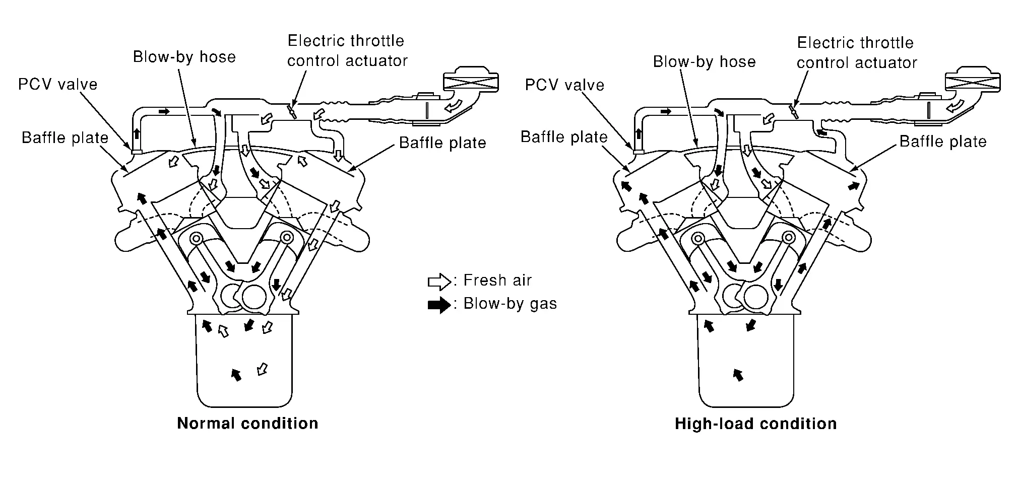
Blow-by gas in the crank case is returned to the intake manifold to improve ventilation efficiency. This allows the intervals of engine oil change to be extended.
When the engine is in the low-middle load condition as shown in the figure
 , the blow-by gas goes to the intake manifold via the PCV valve.
In the general driving conditions, the capacity of the PCV valve is sufficient for treating the blow-by gas and a little amount of the fresh air.
The fresh air enters to the rocker cover from the air duct via a hose, and is guided to the crankcase.
When the engine is in the high load condition as shown in the figure
 , blow-by gas flows backward in the blow-by hose and gets sucked into air duct.
On Board Refueling Vapor Recovery (ORVR)
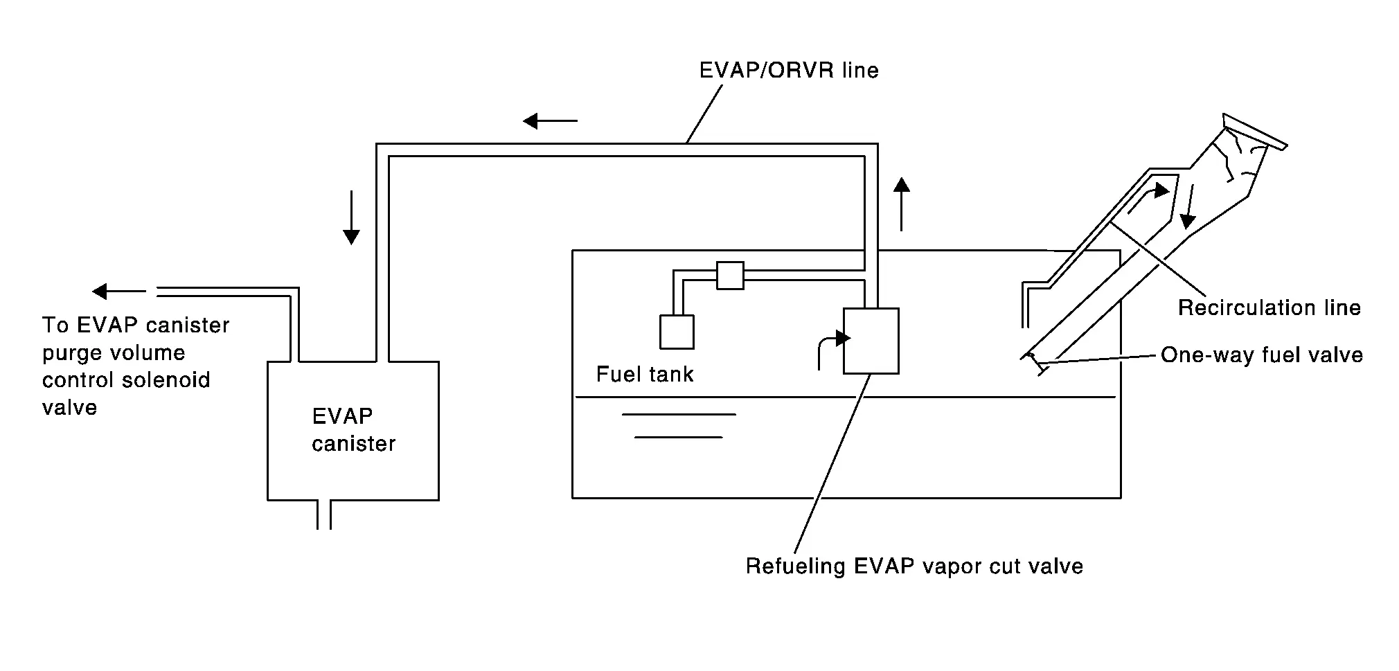
From the beginning of refueling, the air and vapor inside the fuel tank go through refueling EVAP vapor cut valve and EVAP/ORVR line to the EVAP canister. The vapor is absorbed by the EVAP canister and the air is released to the atmosphere.
When the refueling has reached the full level of the fuel tank, the refueling EVAP vapor cut valve is closed and refueling is stopped because of auto shut-off. The vapor which was absorbed by the EVAP canister is purged during driving.
WARNING:
When conducting inspections below, be sure to observe the following:
-
Put a “CAUTION: FLAMMABLE” sign in workshop.
-
Never smoke while servicing fuel system. Keep open flames and sparks away from work area.
-
Always furnish the workshop with a CO2 fire extinguisher.
CAUTION:
-
Before removing fuel line parts, carry out the following procedures:
-
Put drained fuel in an explosion-proof container and put lid on securely.
-
Release fuel pressure from fuel line. Refer to Work Procedure.
-
Disconnect battery ground cable.
-
-
Always replace O-ring when the fuel gauge retainer is removed.
-
Never kink or twist hose and tube when they are installed.
-
Never tighten hose and clamps excessively to avoid damaging hoses.
-
After installation, run engine and check for fuel leaks at connections.
-
Never attempt to top off the fuel tank after the fuel pump nozzle shuts off automatically.
Continued refueling may cause fuel overflow, resulting in fuel spray and possibly a fire.
System ➤ Nissan Pathfinder 2026
Operation Nissan Pathfinder 2026
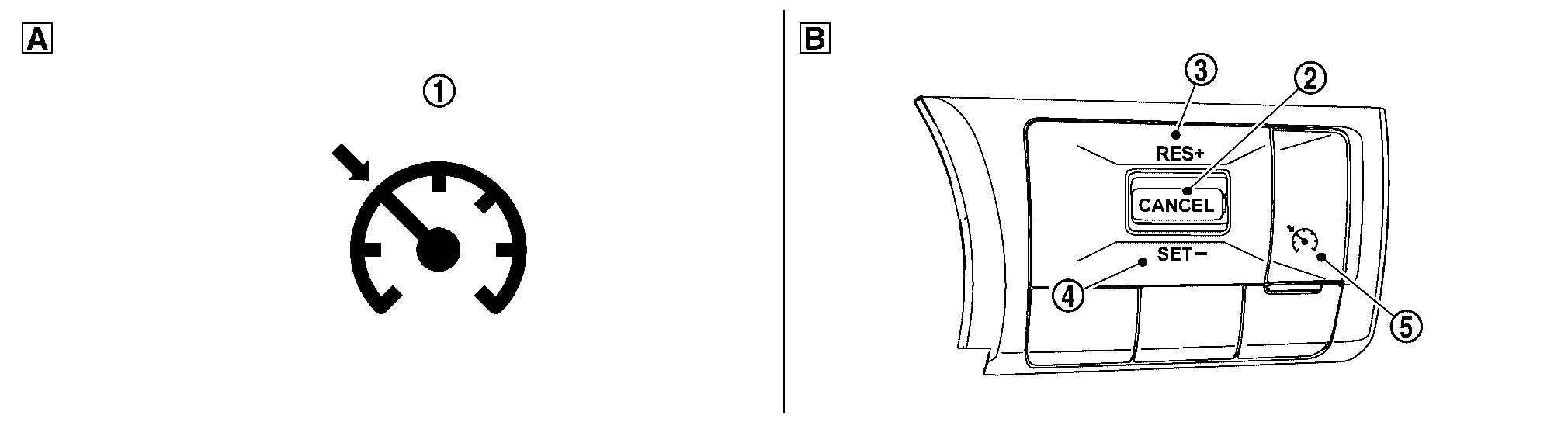
Autmatic Speed Control Device (ascd)
Switch Name and Function
SWITCHES AND INDICATORS
 |
CRUISE indicator |
 |
CANCEL switch |
 |
RES/+ switch |
 |
SET/- switch |
 |
ASCD MAIN switch | ||
 |
On the combination meter (Information display) |
 |
On the steering wheel |
SET SPEED RANGE
ASCD system can be set the following vehicle speed.
| Minimum speed (Approx.) | Maximum speed (Approx.) |
|---|---|
| 40 km/h (25 MPH) | 144 km/h (89 MPH) |
SWITCH OPERATION
| Item | Function |
|---|---|
| CANCEL switch | Cancels the cruise control driving. |
| RES/+ switch |
|
| SET/- switch |
|
| ASCD MAIN switch | Master switch to activate the ASCD system. |
CANCEL OPERATION
When any of following conditions exist, cruise operation will be canceled.
-
CANCEL switch is pressed
-
More than 2 switches at ASCD steering switch are pressed at the same time (Set speed will be cleared)
-
Brake pedal is depressed
-
Selector lever is in the N, P, R position
-
Nissan Pathfinder Vehicle speed decreased to 13 km/h (8 MPH) lower than the set speed
-
TCS system is operated
When the ECM detects any of the following conditions, the ECM will cancel the cruise operation and inform the driver by blinking indicator lamp.
-
Engine coolant temperature is slightly higher than the normal operating temperature, CRUISE lamp may blink slowly.
When the engine coolant temperature decreases to the normal operating temperature, CRUISE lamp will stop blinking and the cruise operation will be able to work by pressing COAST/SET switch or ACCEL/RES switch.
-
Malfunction for some self-diagnoses regarding ASCD control: SET indicator will blink quickly.
If MAIN switch is turned to OFF while ASCD is activated, all of ASCD operations will be canceled and Nissan Pathfinder vehicle speed memory will be erased.
Stop/start System
Switch Name and Function
SWITCHES AND INDICATORS
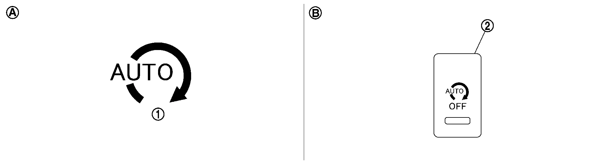
| 1. | Stop/start indicator | 2. | Stop/start OFF switch | ||
| A. | On the information display | B. | Lower instrument panel (driver side) |
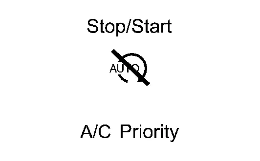
SYSTEM CONTROL CONDITION DISPLAY
Stop/start Indicator Lamp Status
| System condition | Condition | Stop/start indicator lamp | Warning chime |
|---|---|---|---|
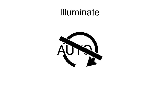
| Operate | Normal | Illuminate | — |
| Hood open* | High speed blinking | Sound | |
| Normal operation: Stop/Start system inhibited state |
System conditions excluded failure are not satisfied. (Battery state of charge, A/C steering operation, driver′s seat belt is unbuckled etc) |
Illuminate
|
— |
| Fail-Safe | Starter motor operation counter: too much | Slow speed blinking | — |
| Malfunction of stop/start system | Slow speed blinking | — |
*: Engine is stalled after alert for 1.5 seconds.
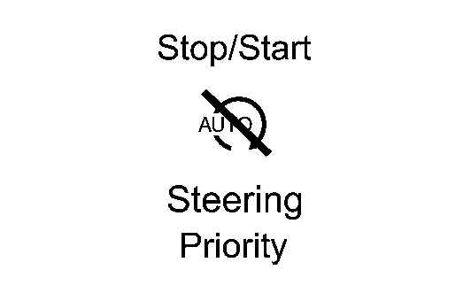
Stop/start Indicator Status (Information Display)
| System condition | Nissan Pathfinder Vehicle condition | Warning chime | Stop/start indicator | |
|---|---|---|---|---|
| Operate | Normal | — |
|
|
| The engine does not restart | With intelligent key system | Hood open*1 | Sound |
|
| The stop/start system is OFF | When the stop/start OFF switch is ON.*2 | — |
|
|
| When the brake pedal is not enough pressure. | — |
|
||
| When A/C is prioritized. | — |
|
||
| When the steering wheel is being operated. | — |
|
||
| Others | — | — | ||
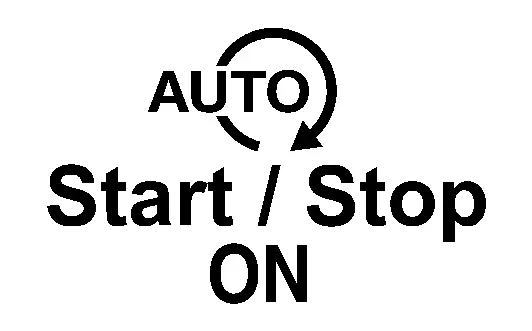
| The stop/start system is ON. | When the stop/start OFF switch is OFF.*3 | — |
|
|
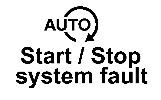
| Fail-Safe | Starter motor operation counter: too much | — |
|
|
| Malfunction of stop/start system | — | |||


*1: Engine is stalled after alert for 1.5 seconds.
*2: This is indicated only for 1.5 seconds after the stop/start OFF switch is turned from OFF to ON.
*3: This is indicated only for 1.5 seconds after the stop/start OFF switch is turned from ON to OFF.
On Board Diagnostic (obd) System Nissan Pathfinder Fifth generation
Diagnosis Description
This system is an on board diagnostic system that records exhaust emission-related diagnostic information and detects a sensors/actuator-related malfunction. A malfunction is indicated by the malfunction indicator lamp (MIL) and stored in ECU memory as a DTC. The diagnostic information can be obtained with the diagnostic tool (GST: Generic Scan Tool).
GST (Generic Scan Tool)
When GST is connected with a data link connector equipped on the vehicle side, it will communicate with the control unit equipped in the Nissan Pathfinder vehicle and then enable various kinds of diagnostic tests. Refer to Diagnosis Description.
 NOTE:
NOTE:
Service $0A is not applied for regions where it is not mandated.
Diagnosis System (ecm) Nissan Pathfinder
Diagnosis Description
1st Trip Detection Logic and Two Trip Detection Logic
When a malfunction is detected for the first time, 1st trip DTC and 1st trip Freeze Frame data are stored in the ECM memory. The MIL will not illuminate at this stage. <1st trip>
If the same malfunction is detected again during the next drive, the DTC and Freeze Frame data are stored in the ECM memory, and the MIL illuminates. The MIL illuminates at the same time when the DTC is stored. <2nd trip> The “trip” in the “Two Trip Detection Logic” means a driving mode in which self-diagnosis is performed during Nissan Pathfinder vehicle operation. Specific on board diagnostic items will cause the ECM to illuminate or blink the MIL, and store DTC and Freeze Frame data, even in the 1st trip, as shown below.
×: Applicable —: Not applicable
| Items | MIL | DTC | 1st trip DTC | |||||
|---|---|---|---|---|---|---|---|---|
| 1st trip | 2nd trip | 1st trip displaying | 2nd trip displaying | 1st trip displaying | 2nd trip displaying | |||
| Blinking | Illuminate | Blinking | Illuminate | |||||
| Misfire (Possible three way catalyst damage) — DTC: P0300 - P0308 is being detected | × | — | — | — | — | — | × | — |
| Misfire (Possible three way catalyst damage) — DTC: P0300 - P0308 is being detected | — | — | × | — | — | × | — | — |
| One trip detection diagnoses. Refer to DTC Index. | — | × | — | — | × | — | — | — |
| Except above | — | — | — | × | — | × | × | — |
DTC and Freeze Frame Data
DTC AND 1ST TRIP DTC
The 1st trip DTC (whose number is the same as the DTC number) is displayed for the latest self-diagnostic result obtained. If the ECM memory was cleared previously, and the 1st trip DTC did not recur, the 1st trip DTC will not be displayed.
If a malfunction is detected during the 1st trip, the 1st trip DTC is saved in the ECM memory. The MIL will not light up (two trip detection logic). If the same malfunction is not detected in the 2nd trip (meeting the required driving pattern), the 1st trip DTC is cleared from the ECM memory. If the same malfunction is detected in the 2nd trip, both the 1st trip DTC and DTC are saved in the ECM memory and the MIL lights up. In other words, the DTC is stored in the ECM memory and the MIL lights up when the same malfunction occurs in two consecutive trips. If a 1st trip DTC is stored and a non-diagnostic operation is performed between the 1st and 2nd trips, only the 1st trip DTC will continue to be stored. For malfunctions that blink or light up the MIL during the 1st trip, the DTC and 1st trip DTC are stored in the ECM memory.
For malfunctions in which 1st trip DTCs are displayed, refer to DTC Index. These items are required by legal regulations to continuously monitor the system/component. In addition, the items monitored non-continuously are also displayed on CONSULT.
1st trip DTC is specified in Service $07 of SAE J1979/ISO 15031-5. 1st trip DTC detection occurs without illuminating the MIL and therefore does not warn the driver of a malfunction.
When a 1st trip DTC is detected, check, print out or write down and erase (1st trip) DTC and Freeze Frame data as specified in Work Flow procedure Step 2, refer to Work Flow. Then perform DTC Confirmation Procedure or Component Function Check to try to duplicate the malfunction. If the malfunction is duplicated, the item requires repair.
FREEZE FRAME DATA AND 1ST TRIP FREEZE FRAME DATA
The ECM records the driving conditions such as fuel system status, calculated load value, engine coolant temperature, short term fuel trim, long term fuel trim, engine speed, Nissan Pathfinder vehicle speed, absolute throttle position, base fuel schedule and intake air temperature at the moment a malfunction is detected.
Data which are stored in the ECM memory, along with the 1st trip DTC, are called 1st trip freeze frame data. The data, stored together with the DTC data, are called freeze frame data and displayed on CONSULT or GST. The 1st trip freeze frame data can only be displayed on the CONSULT screen.
Only one set of freeze frame data (either 1st trip freeze frame data or freeze frame data) can be stored in the ECM. 1st trip freeze frame data is stored in the ECM memory along with the 1st trip DTC. There is no priority for 1st trip freeze frame data and it is updated each time a different 1st trip DTC is detected. However, once freeze frame data (2nd trip detection/MIL on) is stored in the ECM memory, 1st trip freeze frame data is no longer stored. Remember, only one set of freeze frame data can be stored in the ECM. The ECM has the following priorities to update the data.
| Priority | Items | |
|---|---|---|
| 1 | Freeze frame data |
Misfire — DTC: P0300 - P0308 Fuel Injection System Function — DTC: P0171, P0172, P0174, P0175 |
| 2 | Except the above items | |
| 3 | 1st trip freeze frame data | |
For example, the EGR malfunction (Priority: 2) was detected and the freeze frame data was saved in the 2nd trip. After that when the misfire (Priority: 1) is detected in another trip, the freeze frame data will be updated from the EGR malfunction to the misfire. The 1st trip freeze frame data is updated each time a different malfunction is detected. There is no priority for 1st trip freeze frame data. However, once freeze frame data is stored in the ECM memory, 1st trip freeze data is no longer stored (because only one freeze frame data or 1st trip freeze frame data can be stored in the ECM). If freeze frame data is stored in the ECM memory and freeze frame data with the same priority occurs later, the first (original) freeze frame data remains unchanged in the ECM memory.
Both 1st trip freeze frame data and freeze frame data (along with the DTCs) are cleared when the ECM memory is erased.
Counter System
RELATIONSHIP BETWEEN MIL, 1ST TRIP DTC, DTC, AND DETECTABLE ITEMS
-
When a malfunction is detected for the first time, the 1st trip DTC and the 1st trip freeze frame data are stored in the ECM memory.
-
When the same malfunction is detected in two consecutive trips, the DTC and the freeze frame data are stored in the ECM memory, and the MIL will come on.
-
The MIL will turn OFF after the Nissan Pathfinder vehicle is driven 3 times (driving pattern B) with no malfunction. The drive is counted only when the recorded driving pattern is met (as stored in the ECM). If another malfunction occurs while counting, the counter will reset.
-
The DTC and the freeze frame data will be stored until the Nissan Pathfinder vehicle is driven 40 times (driving pattern A) without the same malfunction recurring (except for Misfire and Fuel Injection System). For Misfire and Fuel Injection System, the DTC and freeze frame data will be stored until the Nissan Pathfinder vehicle is driven 80 times (driving pattern C) without the same malfunction recurring. The “TIME” in “SELF-DIAGNOSTIC RESULTS” mode of CONSULT will count the number of times the Nissan Pathfinder vehicle is driven.
-
The 1st trip DTC is not displayed when the self-diagnosis results in OK for the 2nd trip.
COUNTER SYSTEM CHART
| Items | Fuel Injection System | Misfire | Other |
|---|---|---|---|
| MIL (turns OFF) | 3 (pattern B) | 3 (pattern B) | 3 (pattern B) |
| DTC, Freeze Frame Data (no display) | 80 (pattern C) | 80 (pattern C) | 40 (pattern A) |
| 1st Trip DTC (clear) | 1 (pattern C), *1 | 1 (pattern C), *1 | 1 (pattern B) |
| 1st Trip Freeze Frame Data (clear) | *1, *2 | *1, *2 | 1 (pattern B) |
For details about patterns B and C under “Fuel Injection System” and “Misfire”, see “EXPLANATION FOR DRIVING PATTERNS FOR “MISFIRE <EXHAUST QUALITY DETERIORATION>”, “FUEL INJECTION SYSTEM”.
For details about patterns A and B under Other, see “EXPLANATION FOR DRIVING PATTERNS FOR “MISFIRE <EXHAUST QUALITY DETERIORATION>”, “FUEL INJECTION SYSTEM”.
-
*1: Clear timing is at the moment OK is detected.
-
*2: Clear timing is when the same malfunction is detected in the 2nd trip.
Relationship Between MIL, DTC, 1st Trip DTC and Driving Patterns for “Misfire <Exhaust Quality Deterioration>”, “Fuel Injection System”
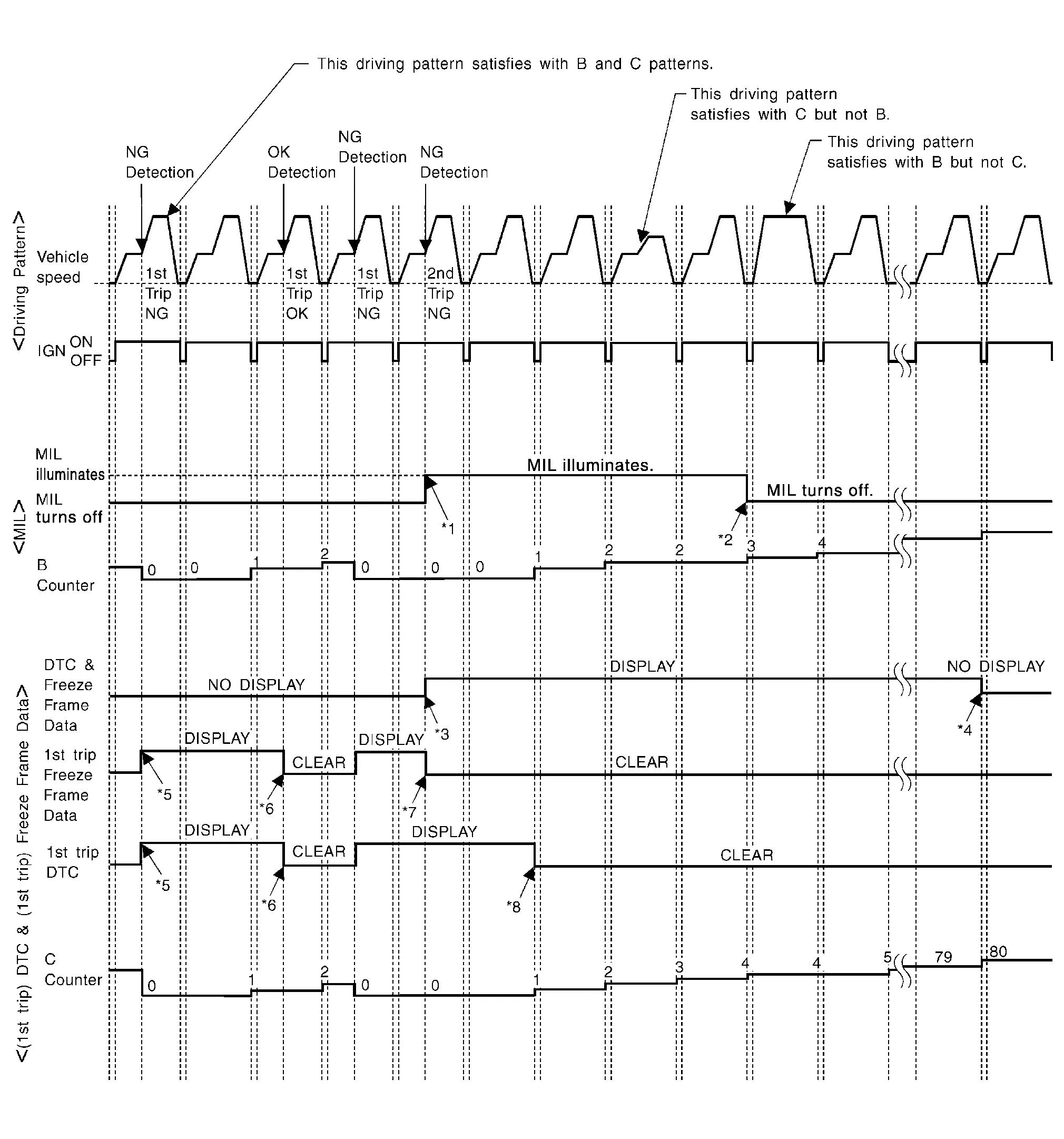
| *1: | When the same malfunction is detected in two consecutive trips, MIL will light up. | *2: | MIL will turn OFF after Nissan Pathfinder vehicle is driven 3 times (pattern B) without any malfunctions. | *3: | When the same malfunction is detected in two consecutive trips, the DTC and the freeze frame data will be stored in ECM. |
| *4: | The DTC and the freeze frame data will not be displayed any longer after Nissan Pathfinder vehicle is driven 80 times (pattern C) without the same malfunction. (The DTC and the freeze frame data still remain in ECM.) | *5: | When a malfunction is detected for the first time, the 1st trip DTC and the 1st trip freeze frame data will be stored in ECM. | *6: | The 1st trip DTC and the 1st trip freeze frame data will be cleared at the moment OK is detected. |
| *7: | When the same malfunction is detected in the 2nd trip, the 1st trip freeze frame data will be cleared. | *8: | 1st trip DTC will be cleared when Nissan Pathfinder vehicle is driven once (pattern C) without the same malfunction after DTC is stored in ECM. |
Explanation for Driving Patterns for “Misfire <Exhaust Quality Deterioration>”, “Fuel Injection System”
Driving Pattern B
Refer to Driving Pattern.
Driving Pattern C
Refer to Driving Pattern.
Example:
If the stored freeze frame data is as per the following:
Engine speed: 850 rpm, Calculated load value: 30%, Engine coolant temperature: 80°C (176°F)
To be satisfied with driving pattern C, the vehicle should run under the following conditions:
Engine speed: 475 – 1,225 rpm, Calculated load value: 27 – 33%, Engine coolant temperature: more than 70°C (158°F)
Relationship Between MIL, DTC, 1st Trip DTC and Driving Patterns Except For “Misfire <Exhaust Quality Deterioration>”, “Fuel Injection System”
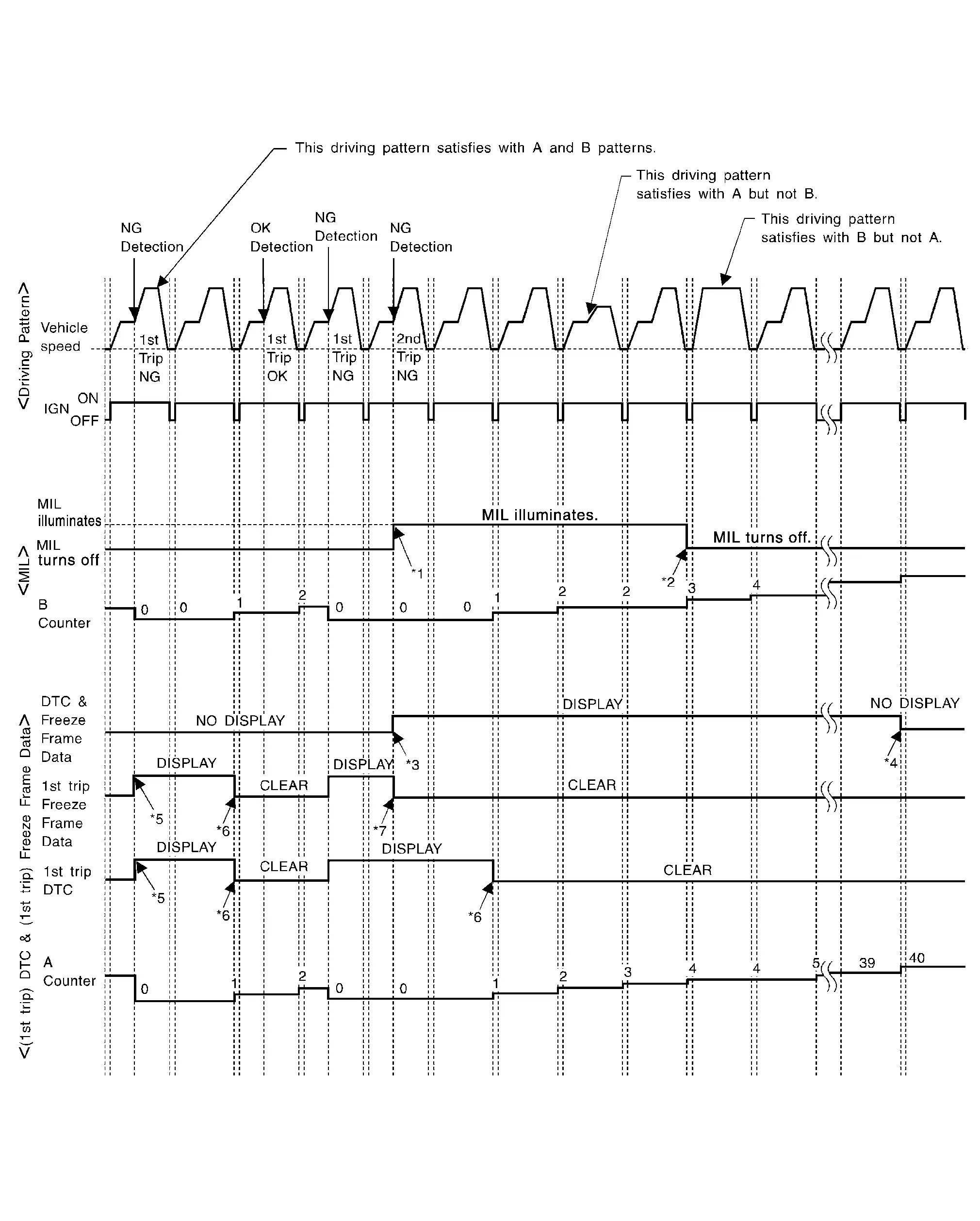
| *1: | When the same malfunction is detected in two consecutive trips, MIL will light up. | *2: | MIL will turn OFF after Nissan Pathfinder vehicle is driven 3 times (pattern B) without any malfunctions. | *3: | When the same malfunction is detected in two consecutive trips, the DTC and the freeze frame data will be stored in ECM. |
| *4: |
The DTC and the freeze frame data will not be displayed any longer after Nissan Pathfinder vehicle is driven 40 times (pattern A) without the same malfunction. (The DTC and the freeze frame data still remain in ECM.) |
*5: | When a malfunction is detected for the first time, the 1st trip DTC and the 1st trip freeze frame data will be stored in ECM. | *6: | 1st trip DTC will be cleared after Nissan Pathfinder vehicle is driven once (pattern B) without the same malfunction. |
| *7: | When the same malfunction is detected in the 2nd trip, the 1st trip freeze frame data will be cleared. |
Explanation for Driving Patterns Except for “Misfire <Exhaust Quality Deterioration>”, “Fuel Injection System”
Driving Pattern A
Refer to Driving Pattern.
Driving Pattern B
Refer to Driving Pattern.
Driving Pattern
CAUTION:
Always drive at a safe speed.
DRIVING PATTERN A
Driving pattern A means a trip satisfying the following conditions.
-
Engine speed reaches 400 rpm or more.
-
Engine coolant temperature rises by 20°C (36°F) or more after starting the engine.
-
Engine coolant temperature reaches 70°C (158°F) or more.
-
The ignition switch is turned from ON to OFF.
 NOTE:
NOTE:
-
When the same malfunction is detected regardless of driving conditions, reset the counter of driving pattern A.
-
When the above conditions are satisfied without detecting the same malfunction, reset the counter of driving pattern A.
DRIVING PATTERN B
Driving pattern B means a trip satisfying the following conditions.
-
Engine speed reaches 400 rpm or more.
-
Engine coolant temperature reaches 70°C (158°F) or more.
-
Nissan Pathfinder Vehicle speed of 70 – 120 km/h (44 – 75 MPH) is maintained for 60 seconds or more under the control of closed loop.
-
Nissan Pathfinder Vehicle speed of 30 – 60 km/h (19 – 37 MPH) is maintained for 10 seconds or more under the control of closed loop.
-
Under the closed loop control condition, the following state reaches 12 seconds or more in total: Nissan Pathfinder Vehicle speed of 4 km/h (2 MPH) or less with idling condition.
-
The state of driving at 10 km/h (7 MPH) or more reaches 10 minutes or more in total.
-
A lapse of 22 minutes or more after engine start.
 NOTE:
NOTE:
-
Drive the vehicle at a constant velocity.
-
When the same malfunction is detected regardless of driving conditions, reset the counter of driving pattern B.
-
When the above conditions are satisfied without detecting the same malfunction, reset the counter of driving pattern B.
DRIVING PATTERN C
Driving pattern C means operating vehicle as per the following:
The following conditions should be satisfied at the same time:
Engine speed: (Engine speed in the freeze frame data) ±375 rpm
Calculated load value: (Calculated load value in the freeze frame data) x (1±0.1) [%]
Engine coolant temperature condition:
-
When the freeze frame data shows lower than 70°C (158°F), engine coolant temperature should be lower than 70°C (158°F).
-
When the freeze frame data shows higher than or equal to 70°C (158°F), engine coolant temperature should be higher than or equal to 70°C (158°F).
 NOTE:
NOTE:
-
When the same malfunction is detected regardless of the above Nissan Pathfinder vehicle conditions, reset the counter of driving pattern C.
-
When the above conditions are satisfied without detecting the same malfunction, reset the counter of driving pattern C.
-
The 1st trip DTC will be cleared when C counter is counted once without the same malfunction after DTC is stored in ECM.
DRIVING PATTERN D
Driving pattern D means a trip satisfying the following conditions.
-
The state of driving at 40 km/h (25 MPH) reaches 300 seconds or more in total.
-
Idle speed lasts 30 seconds or more.
-
A lapse of 600 seconds or more after engine start.
 NOTE:
NOTE:
-
When the same malfunction is detected regardless of driving conditions, reset the counter of driving pattern D.
-
When the above conditions are satisfied without detecting the same malfunction, reset the counter of driving pattern D.
System Readiness Test (SRT) Code
System Readiness Test (SRT) code is specified in Service $01 of SAE J1979/ISO 15031-5.
As part of an enhanced emissions test for Inspection & Maintenance (I/M), certain states require the status of SRT be used to indicate whether the ECM has completed self-diagnosis of major emission systems and components. Completion must be verified in order for the emissions inspection to proceed.
If a vehicle is rejected for a State emissions inspection due to one or more SRT items indicating “INCMP”, use the information in this Service Manual to set the SRT to “CMPLT”.
In most cases the ECM will automatically complete its self-diagnosis cycle during normal usage, and the SRT status will indicate “CMPLT” for each application system. Once set as “CMPLT”, the SRT status remains “CMPLT” until the self-diagnosis memory is erased.
Occasionally, certain portions of the self-diagnostic test may not be completed as a result of the customer's normal driving pattern; the SRT will indicate “INCMP” for these items.
 NOTE:
NOTE:
The SRT will also indicate “INCMP” if the self-diagnosis memory is erased for any reason or if the ECM memory power supply is interrupted for several hours.
If, during the state emissions inspection, the SRT indicates “CMPLT” for all test items, the inspector will continue with the emissions test. However, if the SRT indicates “INCMP” for one or more of the SRT items the Nissan Pathfinder vehicle is returned to the customer untested.
 NOTE:
NOTE:
If permanent DTC is stored or MIL illuminates during the state emissions inspection, the Nissan Pathfinder vehicle is also returned to the customer untested even though the SRT indicates “CMPLT” for all test items. Therefore, it is important to check SRT (“CMPLT”), DTC (No DTCs) and permanent DTC (NO permanent DTCs) before the inspection.
SRT SET TIMING
SRT is set as “CMPLT” after self-diagnosis has been performed one or more times. Completion of SRT is done regardless of whether the result is OK or NG. The set timing is different between OK and NG results and is shown in the table below.
| Self-diagnosis result | Example | |||||
|---|---|---|---|---|---|---|
| Diagnosis |
Ignition cycle ← ON → OFF ← ON → OFF ← ON → OFF ← ON → | |||||
| All OK | Case 1 | P0400 | OK (1) | — (1) | OK (2) | — (2) |
| P0402 | OK (1) | — (1) | — (1) | OK (2) | ||
| P1402 | OK (1) | OK (2) | — (2) | — (2) | ||
| SRT of EGR | “CMPLT” | “CMPLT” | “CMPLT” | “CMPLT” | ||
| Case 2 | P0400 | OK (1) | — (1) | — (1) | — (1) | |
| P0402 | — (0) | — (0) | OK (1) | — (1) | ||
| P1402 | OK (1) | OK (2) | — (2) | — (2) | ||
| SRT of EGR | “INCMP” | “INCMP” | “CMPLT” | “CMPLT” | ||
| NG exists | Case 3 | P0400 | OK | OK | — | — |
| P0402 | — | — | — | — | ||
| P1402 | NG | — | NG |
NG (Consecutive NG) |
||
|
(1st trip) DTC |
1st trip DTC | — | 1st trip DTC |
DTC (= MIL ON) |
||
| SRT of EGR | “INCMP” | “INCMP” | “INCMP” | “CMPLT” | ||
OK: Self-diagnosis is carried out and the result is OK.
NG: Self-diagnosis is carried out and the result is NG.
—: Self-diagnosis is not carried out.
When all SRT related self-diagnoses show OK results in a single cycle (Ignition OFF-ON-OFF), the SRT will indicate “CMPLT”. → Case 1 above
When all SRT related self-diagnoses show OK results through several different cycles, the SRT will indicate “CMPLT” at the time the respective self-diagnoses have at least one OK result. → Case 2 above
If one or more SRT related self-diagnoses show NG results in 2 consecutive cycles, the SRT will also indicate “CMPLT”. → Case 3 above
The table above shows that the minimum number of cycles for setting SRT as “INCMP” is the number one (1) for each self-diagnosis (Case 1 & 2) or the number two (2) for one of self-diagnoses (Case 3). However, in preparation for the state emissions inspection, it is unnecessary for each self-diagnosis to be executed twice (Case 3) for the following reasons:
-
The SRT will indicate “CMPLT” at the time the respective self-diagnoses have one (1) OK result.
-
The emissions inspection requires “CMPLT” of the SRT only with OK self-diagnosis results.
-
During SRT driving pattern, the 1st trip DTC (NG) is detected prior to “CMPLT” of SRT and the self-diagnosis memory must be erased from the ECM after repair.
-
If the 1st trip DTC is erased, all the SRT will indicate “INCMP”.
 NOTE:
NOTE:
SRT can be set as “CMPLT” together with the DTC(s). Therefore, DTC check must always be carried out prior to the state emission inspection even though the SRT indicates “CMPLT”.
Permanent Diagnostic Trouble Code (Permanent DTC)
Permanent DTC is defined in SAE J1979/ISO 15031-5 Service $0A.
ECM stores a DTC issuing a command of turning on MIL as a permanent DTC and keeps storing the DTC as a permanent DTC until ECM judges that there is no presence of malfunction.
Permanent DTCs cannot be erased by using the Erase function of CONSULT or Generic Scan Tool (GST) and by disconnecting the battery to shut off power to ECM. This prevents a Nissan Pathfinder vehicle from passing the state emission inspection without repairing a malfunctioning part.
When not passing the state emission inspection due to more than one permanent DTC, permanent DTCs should be erased, referring to this manual.
 NOTE:
NOTE:
-
The important items in state emission inspection are that MIL is not ON, SRT test items are set, and permanent DTCs are not included.
-
Permanent DTCs do not apply for regions that permanent DTCs are not regulated by law.
PERMANENT DTC SET TIMING
The setting timing of permanent DTC is stored in ECM with the lighting of MIL when a DTC is confirmed.
Malfunction Indicator Lamp (MIL)
-
When detecting a DTC that affects exhaust gas, the exhaust emission-related control module transmits a malfunction indicator lamp signal to ECM via CAN communication line.
ECM prioritizes (MIL: ON/blink) the signal received from the exhaust emission-related control module and the ECM-stored DTC that affects exhaust gas and transmits a malfunction indicator lamp signal to the combination meter via CAN communication line.
The combination meter turns ON or blinks the MIL, according to the signal transmitted from ECM, and alerts the driver of malfunction detection.
-
Control modules that a DTC of MIL ON/Blink is stored (Control module varies among DTCs.):
-
ECM
-
TCM
-
-
The MIL illuminates when ignition switch is turned ON (engine is not running).
 NOTE:
NOTE:
Check the MIL circuit if MIL does not illuminate. Refer to Component Function Check.
-
When the engine is started, the MIL should go off.
 NOTE:
NOTE:
If MIL remains ON or continues blinking, a DTC(s) that affects exhaust gas is detected. In this case, Self-diagnosis is required for performing inspection and repair.
On Board Diagnosis Function
ON BOARD DIAGNOSIS ITEM
The on board diagnostic system has the following functions.
| Diagnostic test mode | Function |
|---|---|
| Bulb check | MIL can be checked. |
| SRT status | ECM can read if SRT codes are set. |
| Malfunction warning | If ECM detects a malfunction, it illuminates or blinks MIL to inform the driver that a malfunction has been detected. |
| Accelerator pedal released position learning | ECM can learn the accelerator pedal released position. Refer to Description. |
| Throttle valve closed position learning | ECM can learn the throttle valve closed position. Refer to Description. |
| Electric intake valve timing control learning | The initial position of the electric intake valve timing control actuator can be adjusted. Refer to Description. |
BLUB CHECK MODE
Description
This function allows damage inspection in the MIL bulb (blown, open circuit, etc.).
Operation Procedure
-
Turn ignition switch ON.
-
The MIL on the instrument panel should stay ON.
If it remains OFF, check MIL circuit. Refer to Diagnosis Procedure.
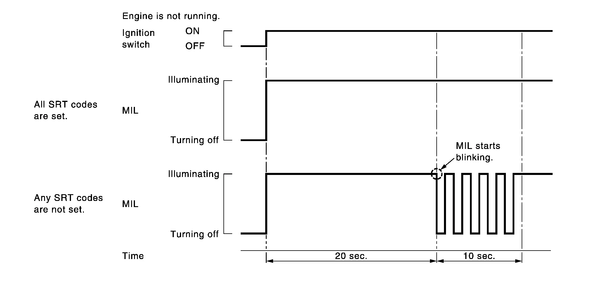
SRT STATUS MODE
Description
This function allows to read if ECM has completed the self-diagnoses of major emission control systems and components. For SRT, refer to System Readiness Test (SRT) Code.
Operation Procedure
-
Turn ignition switch ON and wait 20 seconds.
-
SRT status is indicated as shown blow.
-
ECM continues to illuminate MIL if all SRT codes are set.
-
ECM blinks MIL for about 10 seconds if all SRT codes are not set.
-
MALFUNCTION WARNING MODE
Description
In this function ECM turns on or blinks MIL when it detects a malfunction in the emission control system components and/or the powertrain control components (which affect Nissan Pathfinder vehicle emissions) to inform the driver that a malfunction has been detected.
Operation Procedure
-
Turn ignition switch ON.
-
Check that MIL illuminates.
If it remains OFF, check MIL circuit. Refer to Diagnosis Procedure.
-
Start engine and let it idle.
-
For two trip detection logic diagnoses, ECM turns on MIL when it detects the same malfunction twice in the two consecutive driving cycles.
-
For 1st trip detection logic diagnoses, ECM turns on MIL when it detects a malfunction in one driving cycle.
-
ECM blinks MIL when it detects a malfunction that may damage the three way catalyst (misfire).
-
CONSULT Function
FUNCTION
| Diagnostic test mode | CGW Status | Function | ||
|---|---|---|---|---|
| Restricted Mode | Diag Test Mode | Open Mode | ||
| Self Diagnostic Result | Display | Display | Display | Self-diagnostic results such as 1st trip DTC, DTCs and 1st trip freeze frame data or freeze frame data can be read and erased quickly.*1 Display non-network DTC which ECM memorizes. |
| CGW Information*2 | Display*2 | Display*2 | Display*2 |
|
| Data Monitor | Display | Display | Display | Input/Output data in the ECM can be read. |
| Work Support*2 | Non-display*2 | Non-display*2 | Display*2 | This mode enables a technician to adjust some devices faster and more accurately by following the indications on the CONSULT unit. |
| Active Test*2 | Non-display*2 | Display*2 | Display*2 | Diagnostic Test Mode in which CONSULT drives some actuators apart from the ECMs and also shifts some parameters in a specified range. |
| ECU Identification | Display | Display | Display | ECM part number can be read. |
| DTC Work Support | Non-display | Display | Display | SRT and operating condition to check DTC can be confirmed. |
| MAC Diagnosis*3 | Display | Display | Display |
Display MAC diagnosis result divided into the following two inspection priorities.
|
| CAN Diag Support Monitor*3 | Display | Display | Display |
The mode is indicated, but not monitored |
| Network DTC*3 | Display | Display | Display | Display network DTC which ECM memorizes when performing "Diagnosis (All System)". |
 NOTE:
NOTE:
*1: The following emission-related diagnostic information is cleared when the ECM memory is erased.
-
DTC (Diagnostic trouble codes)
-
1st trip diagnostic trouble codes
-
Freeze frame data
-
1st trip freeze frame data
-
System readiness test (SRT) codes
-
Test values
*2: In some vehicles, it is not malfunctioning in case of no display of "CGW Information". In this case, it is not necessary to switch the CGW status. In Nissan Pathfinder vehicles where "CGW information" is not displayed, "Work Support" and "Active Test" are always displayed.
*3: Displays when performing "Diagnosis (All System)".
CGW INFORMATION
Display the diagnosis mode which a user can perform in Diag Test mode/Open Mode by switching the CGW status form Restricted mode to Diag Test Mode/Open Mode.
For the method of switching CAN Gateway status, Refer to CONSULT Function.
 NOTE:
NOTE:
In some vehicles, it is not malfunctioning in case of no display of "CGW Information". In this case, it is not necessary to switch the CGW status.
SELF DIAGNOSTIC RESULT MODE
Self Diagnostic Item
Regarding items of DTC and 1st trip DTC, refer to DTC Index.
How to Read DTC and 1st Trip DTC
DTCs and 1st trip DTCs related to the malfunction are displayed in “Self-diag results”.
-
When ECM detects a 1st trip DTC, “1t” is displayed for “TIME”.
-
When ECM has detected a current DTC, “0” is displayed for “TIME”.
-
If “TIME” is neither “0” nor “1t”, the DTC occurred in the past and ECM shows the number of times the Nissan Pathfinder vehicle has been driven since the last detection of the DTC.
How to Erase DTC and 1st Trip DTC
 NOTE:
NOTE:
If the ignition switch stays ON after repair work, be sure to turn ignition switch OFF once. Wait at least 10 seconds and then turn it ON (engine stopped) again.
Freeze Frame Data and 1st Trip Freeze Frame Data
| Freeze frame data item* | Description |
|---|---|
| DIAG TROUBLE CODE [PXXXX] | The engine control component part/control system has a trouble code that is displayed as PXXXX. Refer to DTC Index. |
| CAL/LD VALUE [%] | The calculated load value at the moment a malfunction is detected is displayed. |
| COOLANT TEMP [°C] or [°F] | The engine coolant temperature at the moment a malfunction is detected is displayed. |
| L-FUEL TRM-B1 [%] |
|
| L-FUEL TRM-B2 [%] | |
| S-FUEL TRM-B1 [%] |
|
| S-FUEL TRM-B2 [%] | |
| ENGINE SPEED [rpm] | The engine speed at the moment a malfunction is detected is displayed |
| VEHICL SPEED [km/h] or [mph] | The Nissan Pathfinder vehicle speed at the moment a malfunction is detected is displayed |
| ABSOL TH·P/S [%] | The throttle valve opening angle at the moment a malfunction is detected is displayed |
| B/FUEL SCHDL [msec] | The base fuel schedule at the moment a malfunction is detected is displayed |
| INT/A TEMP SE [°C] or [°F] | The intake air temperature at the moment a malfunction is detected is displayed |
| FUEL SYS-B1 |
|
| FUEL SYS-B2 | |
| INT MANI PRES [kPa] | These items are displayed but are not applicable to this model. |
| COMBUST CONDITION | |
| FUEL RAIL PRESSURE [MPa] | The fuel rail pressure at the moment a malfunction is detected is displayed. |
| TARGET FUEL RAIL PRESSURE [MPa] | The target fuel rail pressure at the moment a malfunction is detected is displayed. |
| BATTERY VOLTAGE [V] | The battery voltage at the moment a malfunction is detected is displayed. |
| FUEL LEVEL [%] | The fuel level at the moment a malfunction is detected is displayed. |
| ODO/TRIP METER [km] | The ODO/TRIP at the moment a malfunction is detected is displayed. |
| DTC count | The engine control component part/control system has a trouble code the is displayed |
*: The items are the same as those of 1st trip freeze frame data.
DATA MONITOR MODE
 NOTE:
NOTE:
-
The following table includes information (items) inapplicable to this Nissan Pathfinder vehicle. For information (items) applicable to this vehicle, refer to CONSULT display items.
-
For reference values of the following items, refer to Reference Value.
Monitored Item
| Monitored item | Unit | Monitor Item Selection | Description | Remarks | ||
|---|---|---|---|---|---|---|
| ECU INPUT SIGNALS | MAINSIGNALS | Stop/Start error | ||||
| COOLANT TEMP/S | °C or °F | × | × | The engine coolant temperature (determined by the signal voltage of the engine coolant temperature sensor) is displayed. | When the engine coolant temperature sensor is open or short-circuited, ECM enters fail-safe mode. The engine coolant temperature determined by the ECM is displayed. | |
| VHCL SPEED SE | km/h or mph | × | × | The Nissan Pathfinder vehicle speed computed from the vehicle speed signal sent from combination meter is displayed. | ||
| BATTERY VOLT | V | The power supply voltage of ECM is displayed. | ||||
| INT/A TEMP SE | °C or °F | × | × | The intake air temperature (determined by the signal voltage of the intake air temperature sensor) is indicated. | ||
| PURG VOL C/V | % |
|
||||
| FUEL T/TMP SE | °C or °F | The fuel temperature (determined by the signal voltage of the fuel tank temperature sensor) is displayed. | ||||
| FUEL LEVEL SE | V | × | The signal voltage of the fuel level sensor is displayed. | |||
| EVAP SYS PRES | V | The signal voltage of EVAP control system pressure sensor is displayed. | ||||
| CAL/LD VALUE | % | “Calculated load value” indicates the value of the current air flow divided by peak air flow. | ||||
| HO2S2 (B1) | V | × | × | The signal voltage of the heated oxygen sensor 2 is displayed. | ||
| HO2S2 (B2) | ||||||
| ENG OIL TEMP | °C or °F | The engine oil temperature (determined by the signal voltage of the engine oil temperature sensor) is displayed. | ||||
| A/F ALPHA-B1 | % | The mean value of the air-fuel ratio feedback correction factor per cycle is indicated. |
|
|||
| A/F ALPHA-B2 | ||||||
| A/F S1 HTR (B1) |
% |
|
||||
| A/F S1 HTR (B2) | ||||||
| EXH/V TIM B1 | °CA | Indicates [°CA] of exhaust camshaft retard angle. | ||||
| EXH/V TIM B2 | ||||||
| Ignition timing | deg | × | × |
Indicates the ignition timing computed by ECM according to the input signals.
Indicates degree from BTDC (Before Top Dead Center) of compression stroke. |
|
|
| FAN DUTY | % | Indicates a command value for cooling fan. The value is calculated by ECM based on input signals. | ||||
| FUEL PUMP DUTY | — | The control condition of the fuel pump control module (FPCM) (determined by ECM according to the input signals) is indicated. | ||||
| THRTL STK CNT B1 | — |
The item is indicated, but not used. |
||||
| ENG SPEED | rpm | × | × | Indicates the engine speed computed from the signal of the crankshaft position sensor (POS) and camshaft position sensor (PHASE). |
|
|
| TRVL AFTER MIL | km or mile | Distance traveled while MIL is activated. | ||||
| B/FUEL SCHDL | ms | × | × | “Base fuel schedule” indicates the fuel injection pulse width programmed into ECM, prior to any learned on board correction. |
Specification value is indicated on monitor screen under the following conditions.
|
|
| MASS AIRFLOW | g/s | Indicates the mass air flow computed by ECM according to the signal voltage of the mass air flow sensor. | ||||
| FUEL PRES SEN | MPa | Indicates the fuel rail pressure computed by ECM according to the input signals. | ||||
| ACCEL SEN 1 | V | The accelerator pedal position sensor signal voltage is displayed. | ACCEL SEN 2 signal is converted by ECM internally. Thus, they differs from ECM terminal voltage signal. | |||
| ACCEL SEN 2 | ||||||
| TP SEN 1-B1 | V | × | × | The throttle position sensor signal voltage is displayed. | TP SEN 2-B1 signal is converted by ECM internally. Thus, they differs from ECM terminal voltage signal. | |
| TP SEN 2-B1 | ||||||
| FUEL INJ B1 | msec | ECM-calculated injection pulse width of the fuel injector on the Bank 1 side. | ||||
| FUEL INJ B2 | ||||||
| I/P PULLY SPD | rpm | Indicates the engine speed computed from the input speed sensor signal. | ||||
| Nissan Pathfinder Vehicle SPEED | km/h or mph | The vehicle speed computed from the Nissan Pathfinder vehicle speed signal sent from TCM is displayed. | ||||
| AC PRESS SEN | V | The signal voltage from the refrigerant pressure sensor is displayed. | ||||
| A/F SEN1 (B1) | V | × | × | The A/F signal computed from the input signal of the air fuel ratio (A/F) sensor 1 is displayed. | ||
| A/F SEN1 (B2) | ||||||
| VHCL SPEED SE | km/h or mph | The Nissan Pathfinder vehicle speed computed from the vehicle speed signal sent from combination meter is displayed. | ||||
| VTC DTY EX B1 | % | The control condition of the exhaust valve timing control solenoid valve (determined by ECM according to the input signals) is indicated. | ||||
| VTC DTY EX B2 | ||||||
| A/F ADJ-B1 | — | Indicates the correction of factor stored in ECM. The factor is calculated from the difference between the target air-fuel ratio stored in ECM and the air-fuel ratio calculated from A/F sensor 1 signal. | ||||
| A/F ADJ-B2 | ||||||
| INT/V TIM (B1) | °CA | Indicates [°CA] of intake camshaft advance angle. | ||||
| INT/V TIM (B2) | ||||||
| H/P FUEL PUMP DEG | deg | Displays ECM-calculated fuel discharge position of the high pressure fuel pump. | ||||
| FUEL PRES SEN V | V | The signal voltage of FRP sensor is displayed. | ||||
| EOP SENSOR | V | The signal voltage of EOP sensor is displayed. | ||||
| ECM TEMP 1 | °C | The ECM temperature is indicated. | ||||
| ECM TEMP 2 | ||||||
| Mass air flow sensor (HZ) B1 | Hz | The signal frequency of the mass air flow sensor is displayed. | ||||
| LOAD SIGNAL | On/Off | × | × |
Indicates [On/Off] condition from the electrical load signal.
|
||
| AIR COND SIG | On/Off | × | × | Indicates [On/Off] condition of the air conditioner switch as determined by the air conditioner signal. | ||
| PW/ST SIGNAL | On/Off | × | × | [On/Off] condition of the power steering system (determined by the signal voltage of the power steering pressure sensor signal) is indicated. | ||
| P/N POSI SW | On/Off | × | × | Indicates [On/Off] condition from the park/neutral position (PNP) signal. | ||
| START SIGNAL | On/Off | Indicates start signal status [On/Off] computed by the ECM according to the signals of engine speed and battery voltage. | After starting the engine, [Off] is displayed regardless of the starter signal. | |||
| CLSD THL POS | On/Off | × | × | Indicates idle position [On/Off] computed by ECM according to the accelerator pedal position sensor signal. | ||
| HO2S2 MNTR (B1) | RICH/LEAN | × |
Display of heated oxygen sensor 2 signal:
|
When the engine is stopped, a certain value is indicated. | ||
| HO2S2 MNTR (B2) | × | |||||
| IGNITION SW | On/Off | × | × | Indicates [On/Off] condition from ignition switch signal. | ||
| HEATER FAN SW | On/Off | × | Indicates [On/Off] condition from the heater fan switch signal. | |||
| IDL A/V LEARN | YET/CMPLT |
Displays the condition of Idle Air Volume Learning
|
||||
| BRAKE SW | On/Off | Indicates [On/Off] condition from the stop lamp switch signal. | ||||
| COMBUSTION | — | These items are displayed but are not applicable to this model. | ||||
| VIAS S/V-1 | On/Off | × |
The control condition of the VIAS control solenoid valve 1 (determined by ECM according to the input sig-nals) is indicated.
|
|||
| ENGINE MOUNT | IDLE/TRVL |
The control condition of the electronic controlled engine mount (determined by ECM according to the input signals) is indicated.
|
||||
| FUEL PUMP RLY | On/Off | Indicates the fuel pump relay control condition determined by ECM according to the input signals. | ||||
| FPCM | Hi/Mid/Low/Off | The control condition of the fuel pump control module (FPCM) (determined by ECM according to the input signals) is indicated. | ||||
| VENT CONT/V | On/Off |
The control condition of the EVAP canister vent control valve (determined by ECM according to the input signals) is indicated.
|
||||
| THRTL RELAY | On/Off | Indicates the throttle control motor relay control condition determined by the ECM according to the input signals. | ||||
| HO2S2 HTR (B1) | On/Off | Indicates [On/Off] condition of heated oxygen sensor 2 heater determined by ECM according to the input signals. | ||||
| HO2S2 HTR (B2) | ||||||
| DIST SW | On/Off | Indicates [On/Off] condition from DISTANCE switch signal. | ||||
| BRAKE SW2 | On/Off | Indicates [On/Off] condition of stop lamp switch signal. | ||||
| BRAKE SW1 | On/Off | Indicates [On/Off] condition from brake pedal position switch signal. | ||||
| SET SW | On/Off | Indicates [On/Off] condition from COAST/SET switch signal. | ||||
| RESUME/ACC SW | On/Off | Indicates [On/Off] condition from ACCEL/RES switch signal. | ||||
| CANCEL SW | On/Off | Indicates [On/Off] condition from CANCEL switch signal. | ||||
| MAIN SW | On/Off | Indicates [On/Off] condition from MAIN switch signal. | ||||
| CRUISE LAMP | On/Off | Indicates [On/Off] condition of CRUISE lamp determined by the ECM according to the input signals. | ||||
| VIAS S/V-2 | On/Off |
The control condition of the VIAS control solenoid valve 2 (determined by ECM according to the input sig-nals) is indicated.
|
||||
| HO2 S2 DIAG1 (B2) | INCMP/CMPLT |
Indicates DTC P0159 self-diagnosis (delayed response) condition.
|
||||
| HO2 S2 DIAG1 (B1) | INCMP/CMPLT |
Indicates DTC P0139 self-diagnosis (delayed response) condition.
|
||||
| HO2 S2 DIAG2 (B2) | INCMP/CMPLT |
Indicates DTC P0159 self-diagnosis (slow response) condition.
|
||||
| HO2 S2 DIAG2 (B1) | INCMP/CMPLT |
Indicates DTC P0139 self-diagnosis (slow response) condition.
|
||||
| EVAP LEAK DIAG | YET/CMPLT |
Indicates the condition of EVAP leak diagnosis.
|
||||
| EVAP DIAG READY | On/Off |
Indicates the ready condition of EVAP leak diagnosis.
|
||||
| SYSTEM 1 DIAGNOSIS A B2 | INCMP/CMPLT |
Indicates DTC P219B self-diagnosis condition.
|
||||
| SYSTEM 1 DIAGNOSIS A B1 | INCMP/CMPLT |
Indicates DTC P219A self-diagnosis condition.
|
||||
| A/F SEN1 DIAG1 (B2) | INCMP/CMPLT |
Indicates DTC P015C or P015D self-diagnosis condition.
|
||||
| A/F SEN1 DIAG1 (B1) | INCMP/CMPLT |
Indicates DTC P015A or P015B self-diagnosis condition.
|
||||
| A/F SEN1 DIAG2 (B2) | INCMP/CMPLT |
Indicates DTC P014E or P014F self-diagnosis condition.
|
||||
| A/F SEN1 DIAG2 (B1) | INCMP/CMPLT |
Indicates DTC P014C or P014D self-diagnosis condition.
|
||||
| SYSTEM 1 DIAGNOSIS B B2 | ABSNT/PRSNT |
Indicates DTC P219B self-diagnosis condition.
|
||||
| SYSTEM 1 DIAGNOSIS B B1 | ABSNT/PRSNT |
Indicates DTC P219A self-diagnosis condition.
|
||||
| A/F SEN1 DIAG3 (B2) | ABSNT/PRSNT |
Indicates DTC P014C, P014D, P015A or P015B self-diagnosis condition.
|
||||
| A/F SEN1 DIAG3 (B1) | ABSNT/PRSNT |
Indicates DTC P014E, P014F, P015C or P015D self-diagnosis condition.
|
||||
| ATOM PRES SEN 2 | V | The signal voltage from the manifold absolute pressure (MAP) sensor is displayed. | ||||
| A/GRLL SHTTR POSITION | F/CLOSE MOVING F/OPEN UNIDTF |
Indicates the status of active grille shutter.
|
||||
| STRT OPR TN CNTR | count | Starter motor operation counter is displayed. | Indicated multiplication value of the starter motor operation of key switch operation and restart. | |||
| A/F LRN CNTR B2 | — |
These items are displayed but are not applicable to this model. |
||||
| A/F LRN CNTR B1 | — |
These items are displayed but are not applicable to this model. |
||||
| TOTAL DISTNC-OCS RST 1 | km | The Multi-way Control Valve position detected by the position sensor is displayed. | ||||
| TOTAL DISTNC-OCS RST 2 | km | Total travel distance of odd meter when Oil Control System is reset. | ||||
| TOTAL DISTNC-OCS RST 3 | km | Total travel distance of odd meter when Oil Control System is reset. (two times ago) | ||||
| DETERIORTN VL-OCS RT 1 | — | Total travel distance of odd meter when Oil Control System is reset. (three times ago) | ||||
| DETERIORTN VL-OCS RT 2 | — | Insicates deterioration condition of the engine oil when Oil Control System is reset. | ||||
| DETERIORTN VL-OCS RT 3 | — | Insicates deterioration condition of the engine oil when Oil Control System is reset. (three times ago) | ||||
| TOTAL DISTNC-OCS WRN 1 | km | Total travel distance of odd meter when Oil Control System remaining distance is zero. | ||||
| TOTAL DISTNC-OCS WRN 2 | km | Total travel distance of odd meter when Oil Control System remaining distance is zero. (two times ago) | ||||
| TOTAL DISTNC-OCS WRN 3 | km | Total travel distance of odd meter when Oil Control System remaining distance is zero. (two times ago) | ||||
| DETERIORTN VL-OCS WRN 1 | — | Insicates deterioration condition of the engine oil when Oil Control System remaining distance is zero. | ||||
| DETERIORTN VL-OCS WRN 2 | — | Insicates deterioration condition of the engine oil when Oil Control System remaining distance is zero. (two times ago) | ||||
| DETERIORTN VL-OCS WRN 3 | — | Insicates deterioration condition of the engine oil when Oil Control System remaining distance is zero. (three times ago) | ||||
| CURRENT DETERIORATN VAL | — | Insicates deterioration condition of the engine oil. | ||||
| Brake operation judgment | On/Off | Indicates [On/Off] condition of Brake operation judgment. | ||||
| A/GRLL SHTTR CALIBRATION | INCMP/ CMPLT |
Indicates initial position learning status of active grille shutter.
|
||||
| A/GRLL SHTTR CIRCUIT DiAG | OK/NG |
Indicates the diagnosis result of active grille shutter circuit.
|
||||
| A/GRLL SHTTR TEMP DIAG | OK/NG |
Indicates the diagnosis result of active grille shutter actuator temperature status.
|
||||
| A/GRLL SHTTR OVER RUN | OK/NG |
Indicates active grille shutter moves beyond normal moving limit.
|
||||
| A/GRLL SHTTR STUCK | OK/NG |
Indicates the diagnosis result of active grille shutter stuck or the operation range less than normal.
|
||||
| A/GRLL SHTTR CALIB DIAG | OK/NG |
Indicates the diagnosis result of initial position learning of active grille shutter.
|
||||
| Starter motor (Counter) | OK/NG | × | When the starter motor exceeds the specified No. of starting operation, NG is displayed. | |||
| Driver's seat belt switch | OK/NG | × | When the malfunction of the Driver's seat belt switch is judged, OK or NG is displayed. | |||
| Engine parts | OK/NG | × | When the malfunction of engine parts related to the stop/start system is judged, OK or NG is displayed. | |||
| ABS error | OK/NG | × | When an ABS abnormality is received from the ABS actuator and electric unit, NG is displayed. | |||
| TCM error | OK/NG | × | When an CVT abnormality is received from the TCM, NG is displayed. | |||
| TCM error B | OK/NG | × | When an DTC abnormality is received from the TCM, NG is displayed. | |||
| VDC error | OK/NG | × | When an VDC abnormality is received from the ABS actuator and electric unit, NG is displayed. | |||
| IPDM error | OK/NG | × | When an abnormal voltage status is received from the IPDM E/R, NG is displayed. | |||
| CAN comm (VDC) A | OK/NG | × | When the communication status with the ABS actuator and electric unit is judged, OK or NG is displayed. | |||
| CAN comm (VDC) B | OK/NG | × | When the communication status with the ABS actuator and electric unit is judged, OK or NG is displayed. | |||
| CAN comm (VDC) C | OK/NG | × | When VDC is judged based on the communication status with the ABS actuator and electric unit, OK or NG is displayed. | |||
| CAN comm (VDC) D | OK/NG | × | When VDC is judged based on the communication status with the ABS actuator and electric unit, OK or NG is displayed. | |||
| CAN comm (VDC) E | OK/NG | × | When VDC is judged based on the communication status with the ABS actuator and electric unit, OK or NG is displayed. | |||
| CAN comm (VDC) F | OK/NG | × | When VDC is judged based on the communication status with the ABS actuator and electric unit, OK or NG is displayed. | |||
| CAN comm (VDC) G | OK/NG | × | When VDC is judged based on the communication status with the ABS actuator and electric unit, OK or NG is displayed. | |||
| CAN comm (VDC) H | OK/NG | × | When VDC is judged based on the communication status with the ABS actuator and electric unit, OK or NG is displayed. | |||
| CAN comm (TCM) A | OK/NG | × | When A/T is judged based on the communication status with the TCM, OK or NG is displayed. | |||
| CAN comm (TCM) B | OK/NG | × | When CVT is judged based on the communication status with the TCM, OK or NG is displayed. | |||
| CAN comm (TCM) C | OK/NG | × | When A/T is judged based on the communication status with the TCM, OK or NG is displayed. | |||
| CAN comm (TCM) D | OK/NG | × | When CVT is judged based on the communication status with the TCM, OK or NG is displayed. | |||
| CAN comm (TCM) E | OK/NG | × | When A/T is judged based on the communication status with the TCM, OK or NG is displayed. | |||
| CAN comm (BCM) A | OK/NG | × | When the communication status with the BCM is judged, OK or NG is displayed. | |||
| CAN comm (BCM) B | OK/NG | × | When the communication status with the BCM is judged, OK or NG is displayed. | |||
| CAN comm (BCM) C | OK/NG | × | When the communication status with the BCM is judged, OK or NG is displayed. | |||
| CAN comm (BCM) D | OK/NG | × | When the communication status with the BCM is judged, OK or NG is displayed. | |||
| CAN comm (BCM) E | OK/NG | × | When the communication status with the BCM is judged, OK or NG is displayed. | |||
| CAN comm (IPDM) A | OK/NG | × | When the communication status with the IPDM E/R is judged, OK or NG is displayed. | |||
| CAN comm (IPDM) B | OK/NG | × | When the communication status with the IPDM E/R is judged, OK or NG is displayed. | |||
| CAN comm (IPDM) C | OK/NG | × | When the communication status with the IPDM E/R is judged, OK or NG is displayed. | |||
| CAN comm (IPDM) D | OK/NG | × | When the communication status with the IPDM E/R is judged, OK or NG is displayed. | |||
| CAN comm (IPDM) E | OK/NG | × | When the communication status with the IPDM E/R is judged, OK or NG is displayed. | |||
| Starter motor relay | OK/NG | × | When the malfunction of the ST/IS relay is judged, OK or NG is displayed. | |||
| Neutral switch | OK/NG | × | When the malfunction of the neutral switch is judged, OK or NG is displayed. | |||
| Clutch switch (Lower) | OK/NG | × | When the malfunction of the Clutch switch (Lower) is judged, OK or NG is displayed. | |||
| Clutch switch (Upper) | OK/NG | × | When the malfunction of the Clutch switch (Upper) is judged, OK or NG is displayed. | |||
| CAN comm (EPS) | OK/NG | × | When the communication status with the steering control module is judged, OK or NG is displayed. | |||
| LIN comm (DC/DC) | OK/NG | × | When the malfunction of DC/DC converter is received from LIN communication status, OK or NG is displayed. | |||
| Negative pressure | OK/NG | × | When the brake booster pressure sensor status is judged, OK or NG is displayed. | |||
 NOTE:
NOTE:
 NOTE:
NOTE:
 NOTE:
NOTE:
 NOTE:
NOTE:
 NOTE:
NOTE:
Any monitored item that does not match the Nissan Pathfinder vehicle being diagnosed is deleted from the display automatically.
WORK SUPPORT MODE
Work Item
| WORK ITEM | CONDITION | USAGE |
|---|---|---|
| VIN REGISTRATION | In this mode, VIN is registered in ECM. | When registering VIN in ECM |
| EVAP SYSTEM CLOSE |
Close the EVAP canister vent control valve in order to make EVAP system close under the following conditions.
|
When detecting EVAP vapor leak in the EVAP system |
| IDLE AIR VOL LEARN | The idle air volume that keeps the engine within the specified range is memorized in ECM. | When learning the idle air volume |
| SELF-LEARNING CONT | The coefficient of self-learning control mixture ratio returns to the original coefficient. | When clearing mixture ratio self-learning value |
| CLSD THL POS LEARN | Ignition switch ON and engine stopped. | When learning the throttle valve closed position |
| A/F INITIAL LEARNING | Air fuel ratio learning frequency is low while idling, learning the air fuel ratio of the idling domain in ECM. | When learning the air fuel ratio. |
| TARGET IGN TIM ADJ* | Idle condition | When adjusting target ignition timing |
| TARGET IDLE RPM ADJ* | Idle condition | When setting target idle speed |
| STRT OPRTN CNTR CLEAR | — | — |
| SAVING DATA FOR REPLC CPU | In this mode, save data that is in ECM. | When ECM is replaced. |
| WRITING DATA FOR REPLC CPU | In this mode, write data stored by “SAVE DATA FOR CPU REPLC” in work support mode to ECM. | When ECM is replaced. |
| ELECTRIC INTAKE VALVE TIMING CONTROL LEARNING | Ignition switch ON and engine stopped. |
After the following parts are replaced.
|
| Misfire count (real-time) | These items are displayed but not used. | — |
| Misfire count (past) | These items are displayed but not used. | — |
| Stop/Start prohibit cause data recorder | Ignition switch: ON (Engine stopped) | Indicates the reason that stop/start system does not operate when Nissan Pathfinder vehicle is stopped on CONSULT. |
| Stop/Start engine stall cause data recorder | Ignition switch: ON (Engine stopped) | Indicates the reason that engine is stalled on CONSULT. |
| Stop/Start engine restart cause data recorder | Ignition switch: ON (Engine stopped) | Indicates the reason that engine is restarted when stop/start system operates on CONSULT. |
| MAC KEY writing | Ignition switch: ON | Write MAC key to ECM. |
 NOTE:
NOTE:
*: This function is not necessary in the usual service procedure.
ACTIVE TEST MODE
Test Item
| TEST ITEM | CONDITION | JUDGEMENT | CHECK ITEM (REMEDY) |
|---|---|---|---|
| AUTO STOP START |
Engine: After warming up, run engine at idle
|
Check the stop/start system operate and restart. |
|
|
CAUTION:
|
|||
| ENG COOLANT TEMP |
|
If trouble symptom disappears, see CHECK ITEM. |
|
| FUEL INJECTION |
|
If trouble symptom disappears, see CHECK ITEM. |
|
| PURG VOL CONT/V |
|
Engine speed changes according to the opening percent. |
|
| FUEL/T TEMP SEN | Change the fuel tank temperature using CONSULT. | ||
| POWER BALANCE |
|
Engine runs rough or dies. |
|
| EXT V/T ASSIGN ANGLE |
|
If malfunctioning symptom disappears, see CHECK ITEM. |
|
| ENGINE MOUNTING |
|
Electronic controlled engine mount makes the operating sound. |
|
| VIAS S/V-1 |
|
Solenoid valve makes the operating sound |
|
| ACTIVE GRILLE SHUTTER |
To check the operation of the active grille shutter, follow the steps below:
|
Active grille shutter fully opens or fully closes. |
|
| VENT CONTROL/V |
|
Solenoid valve makes an operating sound. |
|
| FAN DUTY CONTROL* |
|
Cooling fan speed changes. |
|
| VIAS S/V-2 |
|
Solenoid valve makes the operating sound |
|
| AUTO STOP START |
Engine: After warming up, run engine at idle
|
Check the stop/start system operate and restart. |
|
|
CAUTION:
|
|||
| FPCM |
|
Fuel pump speed changes or stops. |
|
| IGNITION TIMING |
|
If trouble symptom disappears, see CHECK ITEM. | Perform Idle Air Volume Learning. |
*: Leaving cooling fan OFF with CONSULT while engine is running may cause the engine to overheat.
DTC WORK SUPPORT MODE
| Test mode | Test item | Corresponding DTC No. | Reference page |
|---|---|---|---|
| A/F SEN1 | A/F SEN1 (B1) P1275 | — | — |
| A/F SEN1 (B1) P1276 | P0130 | DTC Description | |
| A/F SEN1 (B2) P1286 | P0150 | DTC Description | |
| A/F SENSOR1 (B1) P014C/P014D | — | — | |
| A/F SENSOR1 (B2) P014E/P014F | — | — | |
| EVAPORATIVE SYSTEM | PURG FLOW P0441 | P0441 | DTC Description |
| HO2S2 | HO2S2 (B1) P1146 | P0138 | DTC Description |
| HO2S2 (B1) P1147 | P0137 | DTC Description | |
| HO2S2 (B1) P0139 | P0139 | DTC Description | |
| HO2S2 (B2) P1166 | P0158 | DTC Description | |
| HO2S2 (B2) P1167 | P0157 | DTC Description | |
| HO2S2 (B2) P0159 | P0159 | DTC Description |
SRT STATUS Mode
-
For items whose SRT codes are set, “CMPLT” is displayed on the CONSULT screen; for items whose SRT codes are not set, “INCMP” is displayed.
-
“SRT STATUS” provides the presence or absence of permanent DTCs stored in ECM memory.
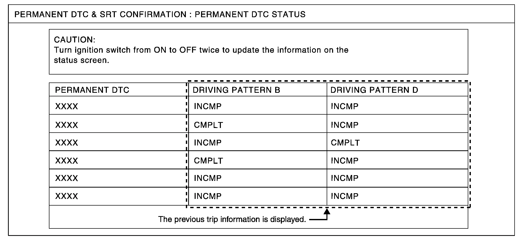
PERMANENT DTC STATUS Mode
How to Display Permanent DTC Status
-
Turn ignition switch OFF and wait at 10 seconds.
-
Turn ignition switch ON.
-
Turn ignition switch OFF and wait at 10 seconds.
-
Turn ignition switch ON.
-
On CONSULT screen, select “SRT & P-DTC”>>“Permanent DTC Status”.
 NOTE:
NOTE:
Permanent DTCs stored in ECM memory are displayed on the CONSULT screen to show if a driving pattern required for erasing permanent DTCs is complete (CMPLT) or incomplete (INCMP).
CAUTION:
Since the “Permanent DTC Status” screen displays the previous trip information, repeat the following twice to update the information: “Ignition switch OFF”, “Wait for more than 10 seconds” and “Ignition switch ON”.
 NOTE:
NOTE:
This mode is not used in regions that permanent DTCs are not regulated by law.
SRT WORK SUPPORT Mode
This mode enables a technician to drive a vehicle to set the SRT while monitoring the SRT status.
PERMANENT DTC WORK SUPPORT Mode
This mode enables a technician to drive a vehicle to complete the driving pattern that is required for erasing permanent DTC.
 NOTE:
NOTE:
This mode is not used in regions that permanent DTCs are not regulated by law.

Nissan Pathfinder (R53) 2022-2026 Service Manual
System Description
- Component Parts ➤
- Structure and Operation
- System ➤
- Operation
- On Board Diagnostic (obd) System
- Diagnosis System (ecm)
Contact Us
Nissan Pathfinder Info Center
Email: info@nipathfinder.com
Phone: +1 (800) 123-4567
Address: 123 Pathfinder Blvd, Nashville, TN 37214, USA
Working Hours: Mon–Fri, 9:00 AM – 5:00 PM (EST)
