Nissan Pathfinder: System Description - System ++
Engine Control System
System Description
SYSTEM DIAGRAM
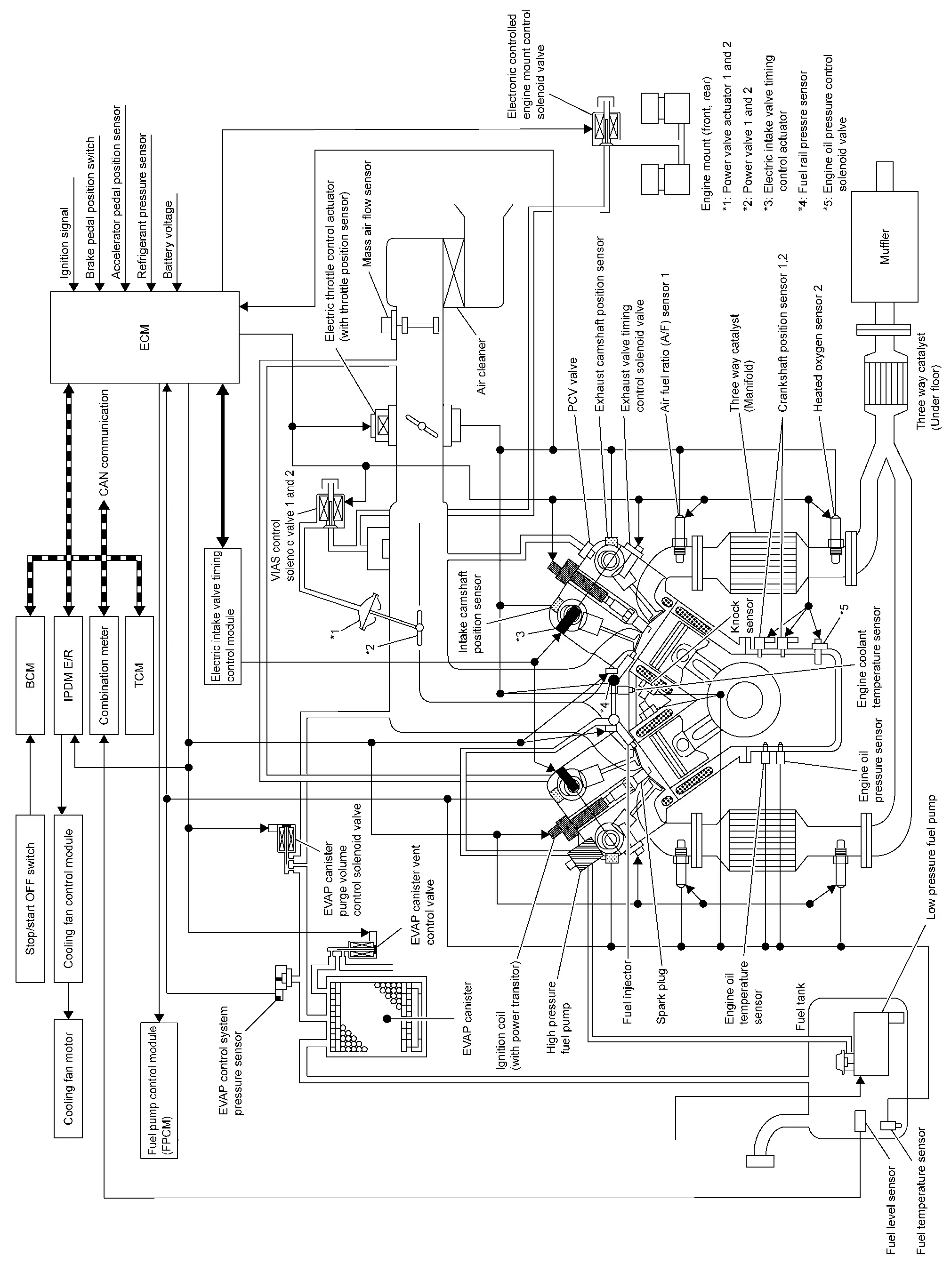
SYSTEM DESCRIPTION
ECM controls the engine by various functions.
| Function | Reference |
|---|---|
| Direct injection gasoline system | System Description |
| Electric ignition system | System Description |
| Fuel pressure control | System Description |
| Fuel pump control module (FPCM) | System Description |
| Intake valve timing control | System Description |
| Exhaust valve timing control | System Description |
| Air conditioning cut system | System Description |
| Engine oil pressure control system | System Description |
| Engine protection control at low engine oil pressure | System Description |
| Cooling fan control | System Description |
| Electronic controlled engine mount | System Description |
| Evaporative emission system | System Description |
| Throttle control | System Description |
| Variable induction air system | System Description |
| Automatic speed control device (ASCD) | System Description |
| Oil control system | System Description |
| Stop/start system | System Description |
| CAN communication | System Description |
Fail safe
Description
When a DTC is detected, ECM executes a mode (in the Fail-safe mode) applicable to the DTC. The fail-safe mode has the preset traveling control mode (accelerator angle variation and engine output limit) and device fix mode.
| Fail safe mode | Nissan Pathfinder Vehicle behavior | Fail safe pattern | |
|---|---|---|---|
| Traveling control mode | Accelerator angle variation control |
ECM controls the accelerator pedal depression speed to make it slower than actual speed. This causes a drop in accelerating performance and encourages the driver to repair malfunction.
ECM does not control the accelerator pedal releasing speed. |
A |
| Engine output control |
ECM reduces the engine output, according to the rise in engine speed. This reduces the Nissan Pathfinder vehicle speed to encourage the driver to repair malfunction.
This value is a reference value converted from engine power to Nissan Pathfinder vehicle speed. Actual power limitation value differs due to the malfunctioning part and driving condition. |
B | |
|
ECM reduces the engine output, according to the rise in engine speed. This reduces the Nissan Pathfinder vehicle speed to encourage the driver to repair malfunction.
This value is a reference value converted from engine power to Nissan Pathfinder vehicle speed. Actual power limitation value differs due to the malfunctioning part and driving condition. |
C | ||
| Device fix mode |
|
D | |
| Combustion control mode | Stratified charge combustion control at starting | No stratified charge combustion at starting (cold start). | E |
| Idle speed control | Stops feedback control of idle speed and controls with specified speed. | F | |
| Recovery speed control at decelerating | Stops recovery speed control by the fuel cut at decelerating and controls with specified speed. | ||
| Idle neutral control | Stops idle neutral control. | ||
| Ignition timing correction control | Partially controls ignition timing control. | G | |
| Retardation control | Controls ignition timing delay control in the intermediate water temperature range. | ||
| Electric throttle control cancel mode | ECM stops the electric throttle control actuator control, throttle valve is maintained at a fixed opening (approx. 5 degrees) by the return spring. | H | |
 NOTE:
NOTE:
 NOTE:
NOTE:
 NOTE:
NOTE:
Fail Safe List
| DTC No. | Detected items | Nissan Pathfinder Vehicle behavior | |||||||||
|---|---|---|---|---|---|---|---|---|---|---|---|
| Pattern | Others | ||||||||||
| A | B | C | D | E | F | G | H | ||||
| C053C | 00 | Nissan Pathfinder Vehicle speed sensor | × | — | — | — | × | — | — | — | — |
|
P0010 P0020 |
00 | Electric intake valve timing control module | — | — | — | × | × | × | — | — | — |
|
P0011 P0012 P0021 P0022 |
00 | Intake valve timing control | — | — | — | × | — | — | — | — | — |
|
P0014 P0015 P0019 P0024 P0025 |
00 | Exhaust valve timing control | — | — | — | × | — | — | — | — | — |
| P0017 | 00 | Exhaust valve timing control | — | — | — | × | — | — | — | — | — |
|
P0078 P0084 |
00 | Exhaust valve timing control solenoid valve | — | — | — | × | — | — | — | — | — |
|
P0087 P0088 P0090 |
00 | Fuel rail pressure control | × | — | — | × | × | — | — | — | — |
|
P0101 P0102 P0103 |
00 | Mass air flow sensor | × | × | — | × | × | × | × | — | — |
|
P0107 P0108 |
00 | Barometric pressure sensor | × | × | — | × | — | — | — | — | — |
|
P0117 P0118 |
00 | Engine coolant temperature sensor | — | — | — | — | × | × | — | — | — |
|
P0122 P0123 P0222 P0223 P2135 |
00 | Throttle position sensor | — | — | — | × | — | — | — | — | — |
|
P0171 P0172 P0174 P0175 |
00 | Fuel injection system | × | — | — | — | × | × | — | — | — |
| P0190 | 00 | Fuel rail pressure sensor | × | — | — | × | × | × | — | — | — |
|
P0191 P0192 P0193 |
00 | × | — | — | — | × | — | — | — | — | |
|
P0201 P0202 P0203 P0204 P0205 P0206 |
00 | Fuel injector | × | — | — | × | × | — | — | — | — |
|
P0300 P0301 P0302 P0303 P0304 P0305 P0306 |
00 | Misfire | × | — | — | — | × | × | — | — | — |
| P0335 | 00 | Crankshaft position sensor | — | — | — | × | × | × | — | — | — |
|
P0340 P0345 |
00 | Intake camshaft position sensor | — | — | — | × | × | × | — | — | — |
|
P0365 P0390 |
00 | Exhaust camshaft position sensor | — | — | — | × | — | — | — | — | — |
| P0500 | 00 | Nissan Pathfinder Vehicle speed sensor | × | — | — | — | × | × | — | — | — |
| P050A | 00 | Cold start control | × | — | — | — | × | — | — | — | |
|
P0604 P0605 P0606 P060B P061B |
00 | ECM | — | — | — | × | — | — | — | × | — |
| P0607 | 00 | × | × | — | — | — | — | — | — | ASCD operation may be deactivated. | |
| P060A | 00 | × | × | — | × | — | — | — | × | ASCD operation may be deactivated. | |
|
P062B P062D P062E |
00 | × | — | — | × | × | — | — | — | — | |
|
P06DD P06DE |
00 | Engine oil pressure control | — | — | — | — | — | — | — | — | Fixes engine oil pressure control valve in the high pressure control position. |
| P0641 | 00 | Sensor power supply | — | — | — | × | × | × | — | — | — |
| P0643 | 00 | — | — | — | × | — | — | — | × | — | |
| P1197 | 00 | Out of gas | — | — | — | × | — | — | — | — | — |
|
P119A P119B P119C |
00 | Fuel pressure sensor | × | — | — | — | × | — | — | — | — |
|
P2100 P2103 |
00 | Throttle control motor relay | — | — | — | × | — | — | — | × | — |
| P2101 | 00 | Electric throttle control | — | — | — | × | — | — | — | × | — |
| P2118 | 00 | Throttle control motor | — | — | — | × | — | — | — | × | — |
| P2119 | 00 | Electric throttle control actuator | × | × | — | × | — | — | — | × | — |
|
P2122 P2123 P2127 P2128 P2138 |
00 | Accelerator pedal position sensor | — | — | — | × | — | — | — | — | — |
|
P23E9 P23EA P2614 P2615 |
00 | Intake camshaft position sensor (electric intake valve timing control signal) | — | — | — | × | × | × | — | — | — |
|
P23EB P2616 |
00 | — | — | — | × | × | — | — | — | — | |
|
P2617 P2618 |
00 | Crankshaft position sensor (electric intake valve timing control signal) | — | — | — | × | × | — | — | — | — |
| P2619 | 00 | — | — | — | × | × | × | — | — | — | |
| P25DF | 00 | Electric intake valve timing control actuator | — | — | — | × | × | — | — | — | — |
| P25E8 | 00 |
ECM stops the electric valve timing control. (The camshaft returns to the position of most retard angle.)
Normal bank transitions intermediate F/S valve timing. |
|||||||||
|
P34AC P34AD P34B1 P34C4 P34C5 |
00 | — | |||||||||
| P34B3 | 00 | Electric intake valve timing control position sensor | — | — | — | × | × | — | — | — | — |
| P34C8 | 00 | Electric intake valve timing control module | — | — | — | × | × | × | — | — | — |
| U0122 | 00 | CAN communication line | × | — | — | — | × | — | — | — | — |
|
U012E U042F |
00 | Engine communication | — | — | — | × | × | × | — | — | — |
 NOTE:
NOTE:
STOP/START SYSTEM
When ECM detects error, ECM detects DTC, prohibits the start/stop system operation, and display the Stop/Start warning indicator. When ECM detects error while operating the stop/start system, ECM restarts the engine.
Auto Engine Shutoff System
System Description
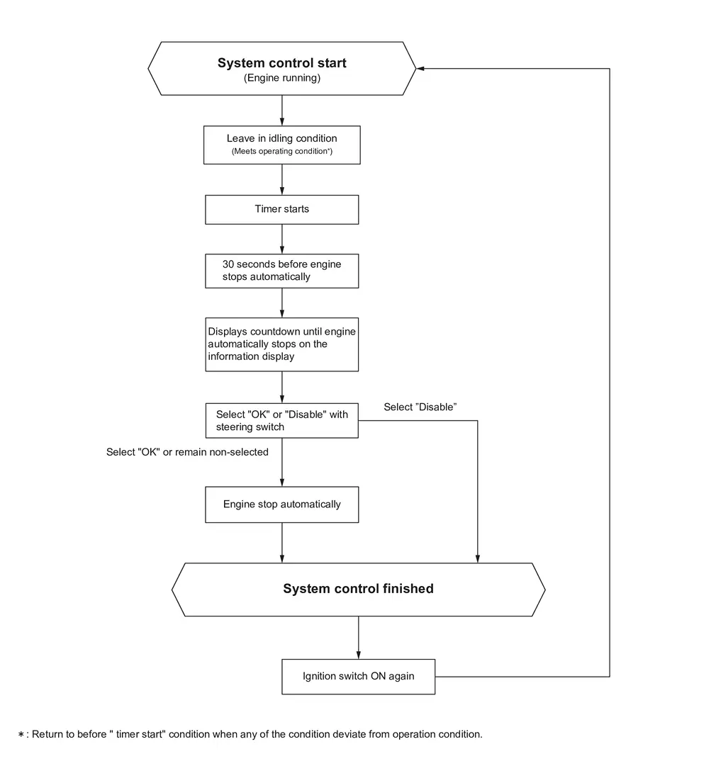
SYSTEM DIAGRAM
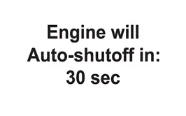
Auto engine shutoff system is a function which is designed to automatically stop the engine after certain while to prevent an extended periods idling.
While idling and system operation condition meets, auto engine shutoff system start operate and timer in the system starts.
When any of the condition is deviate from operation condition, the timer will be reset.
The system display the countdown on the information display from 30 seconds before engine automatically stop.
Auto engine shutoff system can be canceled by steering switch operation even if the countdown announce is displayed.
However, after cancelling the system, when the ignition switch is turned ON again, the system will reset to the operating condition.
| Meets all of 6 conditions | Acceleratorr pedal is not pressed | ||
| Brake pedal is not depressed | |||
| Nissan Pathfinder Vehicle is stopped | |||
| Engine running | |||
| Ignition switch ON | |||
| Meets either of 2 conditions | (For A/T models) Shift position is in P range | ||
| (For M/T models) Meets all of 2 conditions | Shift position is in Neutral position | ||
| Parking brake is in operation | |||
 NOTE:
NOTE:
When driver cancel the Auto engine shutoff system, timer does not start even if above condition meets.
AUTO ENGINE SHUTOFF SYSTEM DISPLAY STATUS (INFORMATION DISPLAY)
Refer to Indicator/Information.
BASIC OPERATION
Direct Injection Gasoline System
System Description
SYSTEM DIAGRAM
| Component parts | Function |
|---|---|
| Crankshaft position sensor 1 | Crankshaft Position Sensor 1 |
| Exhaust camshaft position sensor | Exhaust Camshaft Position Sensor |
|
Mass air flow sensor (With intake air temperature sensor) |
Mass Air Flow Sensor (With Intake Air Temperature Sensor) |
| Intake air temperature sensor | Mass Air Flow Sensor (With Intake Air Temperature Sensor) |
| Engine coolant temperature sensor | Engine Coolant Temperature Sensor |
| Air fuel ratio (A/F) sensor 1 | Air Fuel Ratio (A/F) Sensor 1 |
| Fuel rail pressure sensor | Fuel Rail Pressure Sensor |
| Throttle position sensor | Electric Throttle Control Actuator |
| Accelerator pedal position sensor | Accelerator Pedal Position Sensor |
| Battery | ECM receives the battery voltage signal. |
| Knock sensor | Knock Sensor |
| Heated oxygen sensor 2 | Heated Oxygen Sensor 2 |
| TCM | ECM receives the shift position signal via CAN communication. |
| Power steering control module | ECM receives the EPS operation signal via CAN communication. |
| ABS actuator and electric unit (control unit) |
ECM receives the following signals via CAN communication.
|
| A/C auto amp. | ECM receives the A/C ON signal via CAN communication. |
| Combination meter | ECM receives the Nissan Pathfinder vehicle speed signal via CAN communication. |
| ECM | ECM (With Barometric Pressure Sensor) |
| Fuel injector | Fuel Injector |
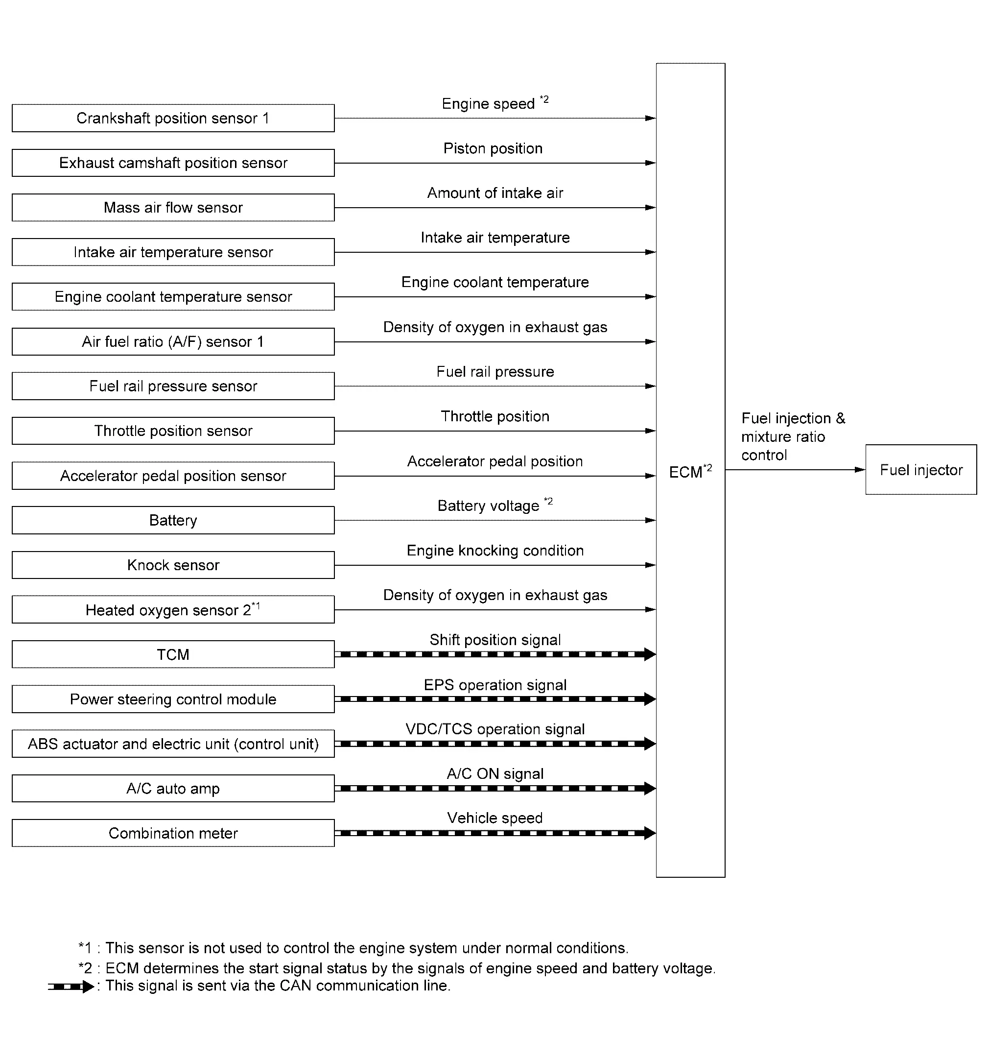
SYSTEM DESCRIPTION
The adoption of the fuel injection method enables more accurate adjustment of fuel injection quantity by injecting atomized high-pressure fuel directly into the cylinder. This method allows high-powered engine, low fuel consumption, and emissions-reduction.
The amount of fuel injected from the fuel injector is determined by the ECM. The ECM controls the length of time the valve remains open (injection pulse duration). The amount of fuel injected is a program value in the ECM memory. The program value is preset by engine operating conditions. These conditions are determined by input signals (for engine speed, intake air, fuel rail pressure and boost pressure) from the crankshaft position sensor 1, exhaust camshaft position sensor, mass air flow sensor and fuel rail pressure sensor.
VARIOUS FUEL INJECTION INCREASE/DECREASE COMPENSATION
In addition, the amount of fuel injected is compensated to improve engine performance under various operating conditions as listed below.
<Fuel increase>
-
During warm-up
-
When starting the engine
-
During acceleration
-
Hot-engine operation
-
When selector lever position is changed from N to D
-
High-load, high-speed operation
<Fuel decrease>
-
During deceleration
-
During high engine speed operation
FUEL INJECTION CONTROL
Catalyst-heating Combustion
Catalyst-heating combustion is a combustion method.
Right after a start with the engine coolant temperature between −12°C (10.2°F) to 40°C (104°F), the catalyst warm-up is accelerated by this combustion.
Homogeneous Combustion
Homogeneous combustion is a combustion method that fuel is injected during intake process so that combustion occurs in the entire combustion chamber, as is common with conventional methods.
As for a start except for starts with the engine cold, homogeneous combustion occurs.
MIXTURE RATIO FEEDBACK CONTROL (CLOSED LOOP CONTROL)
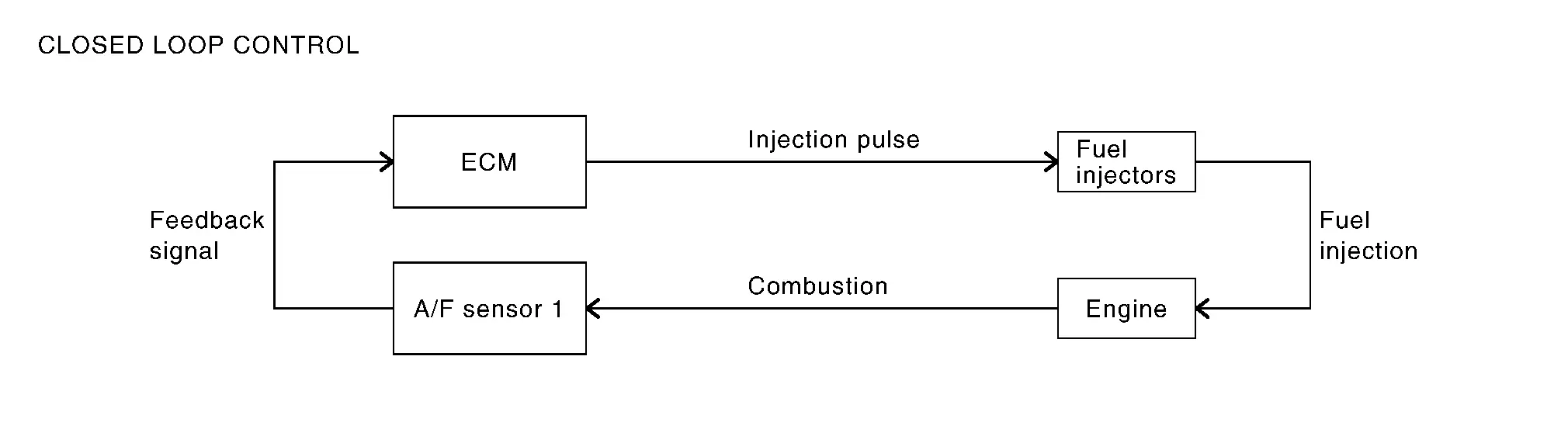
The mixture ratio feedback system provides the best air-fuel mixture ratio for driveability and emission control. The three way catalyst (manifold) can better reduce CO, HC and NOx emissions. This system uses A/F sensor 1 in the exhaust manifold to monitor whether the engine operation is rich or lean. The ECM adjusts the injection pulse width according to the sensor voltage signal. For more information about A/F sensor 1, refer to Air Fuel Ratio (A/F) Sensor 1. This maintains the mixture ratio within the range of stoichiometric (ideal air-fuel mixture).
This stage is referred to as the closed loop control condition.
Heated oxygen sensor 2 senses an oxygen concentration of exhaust gas at downstream of catalytic converter. Even if the switching characteristics of A/F sensor 1 shift, the air-fuel ratio is controlled to stoichiometric by the signal from heated oxygen sensor 2.
-
Open Loop Control
The open loop system condition refers to when the ECM detects any of the following conditions. Feedback control stops in order to maintain stabilized fuel combustion.
-
Deceleration and acceleration
-
High-load, high-speed operation
-
Malfunction of A/F sensor 1 or its circuit
-
Insufficient activation of A/F sensor 1 at low engine coolant temperature
-
High engine coolant temperature
-
During warm-up
-
When starting the engine
-
MIXTURE RATIO SELF-LEARNING CONTROL
The mixture ratio feedback control system monitors the mixture ratio signal transmitted from A/F sensor 1. This feedback signal is then sent to the ECM. The ECM controls the basic mixture ratio as close to the theoretical mixture ratio as possible. However, the basic mixture ratio is not necessarily controlled as originally designed. Both manufacturing differences (i.e., mass air flow sensor sensing element) and characteristic changes during operation (i.e., fuel injector clogging) directly affect mixture ratio.
Accordingly, the difference between the basic and theoretical mixture ratios is monitored in this system. This is then computed in terms of “injection pulse duration” to automatically compensate for the difference between the two ratios.
“Fuel trim” refers to the feedback compensation value compared against the basic injection duration. Fuel trim includes “short-term fuel trim” and “long-term fuel trim”.
“Short term fuel trim” is the short-term fuel compensation used to maintain the mixture ratio at its theoretical value. The signal from A/F sensor 1 indicates whether the mixture ratio is RICH or LEAN compared to the theoretical value. The signal then triggers a reduction in fuel volume if the mixture ratio is rich, and an increase in fuel volume if it is lean.
“Long-term fuel trim” is overall fuel compensation carried out over time to compensate for continual deviation of the “short-term fuel trim” from the central value. Continual deviation will occur due to individual engine differences, wear over time and changes in the usage environment.
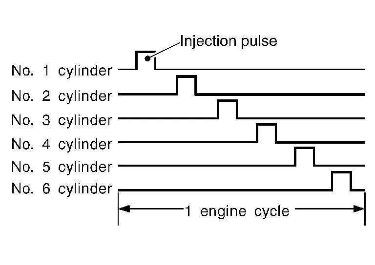
FUEL INJECTION TIMING
Sequential Direct Injection Gasoline System
Fuel is injected into each cylinder during each engine cycle according to the ignition order.
FUEL SHUT-OFF
Fuel to each cylinder is shut-off during deceleration, operation of the engine at excessively high speed or operation of the Nissan Pathfinder vehicle at excessively high speed.
Electric Ignition System
System Description
SYSTEM DIAGRAM
| Component parts | Function |
|---|---|
| Crankshaft position sensor 1 | Crankshaft Position Sensor 1 |
| Exhaust camshaft position sensor | Exhaust Camshaft Position Sensor |
|
Mass air flow sensor (With intake air temperature sensor) |
Mass Air Flow Sensor (With Intake Air Temperature Sensor) |
| Engine coolant temperature sensor | Engine Coolant Temperature Sensor |
| Throttle position sensor | Electric Throttle Control Actuator |
| Accelerator pedal position sensor | Accelerator Pedal Position Sensor |
| Battery | ECM receives the battery voltage signal. |
| Knock sensor | Knock Sensor |
| Heated oxygen sensor 2 | Heated Oxygen Sensor 2 |
| TCM | ECM receives the shift position signal via CAN communication. |
| Combination meter | ECM receives the Nissan Pathfinder vehicle speed signal via CAN communication. |
| ECM | ECM (With Barometric Pressure Sensor) |
|
Ignition coil (With power transistor) |
Ignition Coil and Spark Plug |
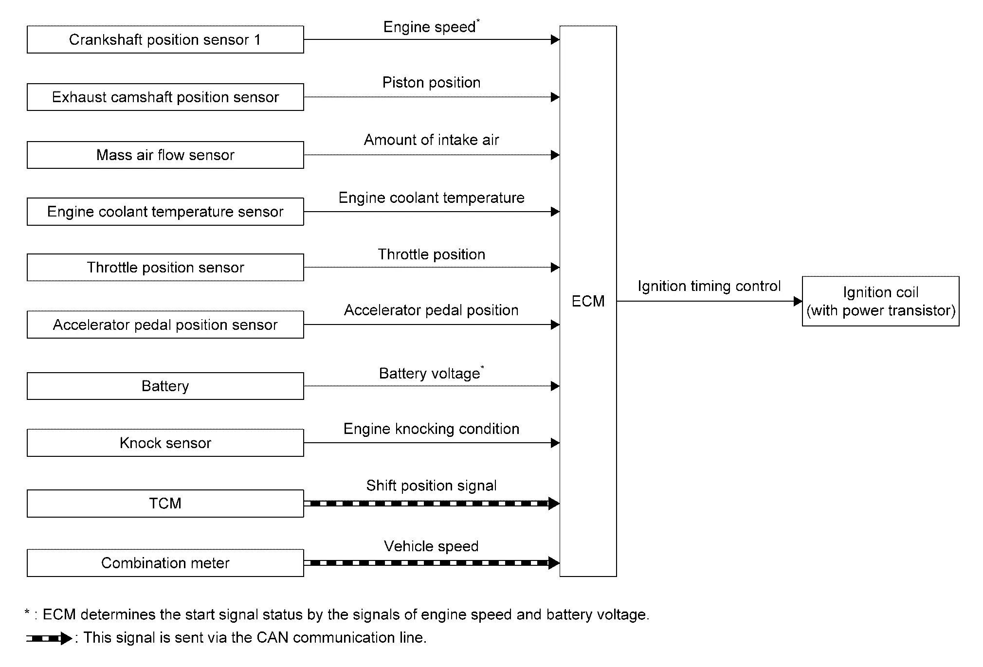
SYSTEM DESCRIPTION
Ignition order: 1 - 2 - 3 - 4 - 5 - 6
The ignition timing is controlled by the ECM to maintain the best air-fuel ratio for every running condition of the engine. The ignition timing data is stored in the ECM.
The ECM receives information such as the injection pulse width and exhaust camshaft position sensor signal. Computing this information, ignition signals are transmitted to the power transistor.
During the following conditions, the ignition timing is revised by the ECM according to the other data stored in the ECM.
-
At starting
-
During warm-up
-
At idle
-
At low battery voltage
-
During acceleration
The knock sensor retard system is designed only for emergencies. The basic ignition timing is programmed within the anti-knocking zone, if recommended fuel is used under dry conditions. The retard system does not operate under normal driving conditions. If engine knocking occurs, the knock sensor monitors the condition. The signal is transmitted to the ECM. The ECM retards the ignition timing to eliminate the knocking condition.
Ignition cylinder detection signals
Fuel Pressure Control
System Description
SYSTEM DIAGRAM
| Component parts | Function |
|---|---|
| Crankshaft position sensor 1 | Crankshaft Position Sensor 1 |
| Exhaust camshaft position sensor | Exhaust Camshaft Position Sensor |
| Fuel rail pressure sensor | Fuel Rail Pressure Sensor |
| Engine coolant temperature sensor | Engine Coolant Temperature Sensor |
| Throttle position sensor | Electric Throttle Control Actuator |
| Accelerator pedal position sensor | Accelerator Pedal Position Sensor |
| Battery | ECM receives the battery voltage signal. |
| ECM | ECM (With Barometric Pressure Sensor) |
| High pressure fuel pump | High Pressure Fuel Pump |
| FPCM | Fuel Pump Control Module |
| Low pressure fuel pump | Low Pressure Fuel Pump |
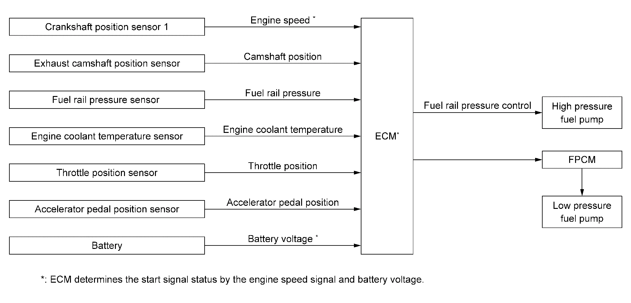
SYSTEM DESCRIPTION
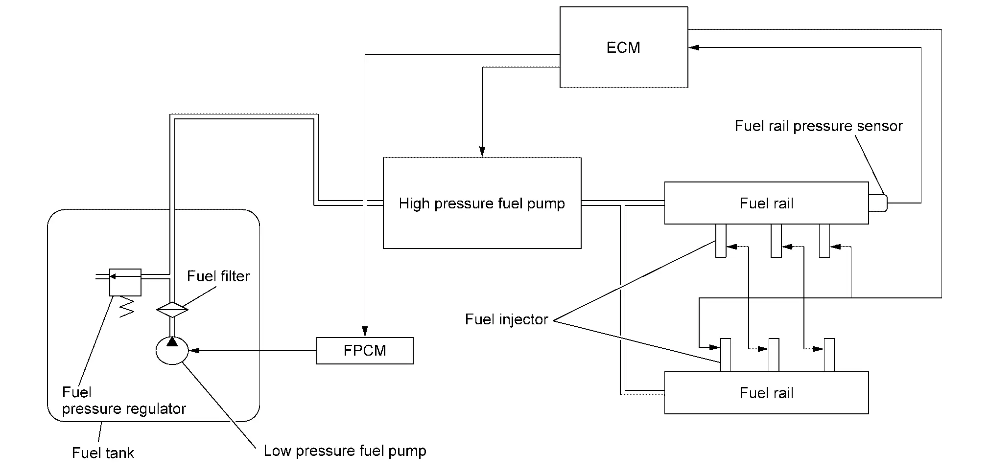
LOW FUEL PRESSURE CONTROL
-
The low fuel pressure pump is controlled by ECM. The pumped fuel passes through the fuel filter and is sent to the high pressure fuel pump.
-
Low fuel pressure is adjusted by the fuel pressure regulator.
HIGH FUEL PRESSURE CONTROL
The high pressure fuel pump raises the pressure of the fuel sent from the low pressure fuel pump. Actuated by the exhaust camshaft, the high pressure fuel pump activates the high pressure fuel pump solenoid based on a signal received from ECM, and adjusts the amount of discharge by changing the timing of closing the inlet check valve to control fuel rail pressure.
Fuel Pump Control Module (fpcm)
System Description
SYSTEM DIAGRAM
| Component parts | Function |
|---|---|
| Crankshaft position sensor 1 | Crankshaft Position Sensor 1 |
| Exhaust camshaft position sensor | Exhaust Camshaft Position Sensor |
| Engine coolant temperature sensor | Engine Coolant Temperature Sensor |
|
Mass air flow sensor (With intake air temperature sensor) |
Mass Air Flow Sensor (With Intake Air Temperature Sensor) |
| Battery | ECM receives the battery voltage signal. |
| ECM | ECM (With Barometric Pressure Sensor) |
| FPCM | Fuel Pump Control Module |
| Low pressure fuel pump | Low Pressure Fuel Pump |
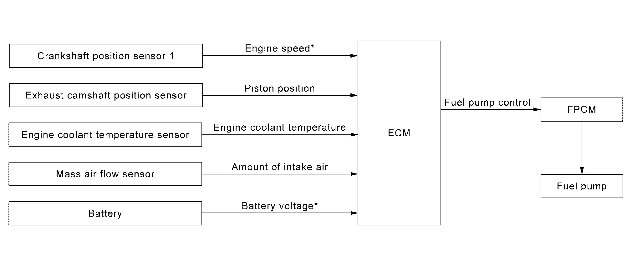
SYSTEM DESCRIPTION
The fuel pump control module (FPCM) controls the discharging volume of the fuel pump by the FPCM control signals (Low/Mid/High) depending on driving conditions.
| Conditions | Amount of fuel flow | Supplied voltage (Approx.) |
|---|---|---|
| For 1 second after turning ignition switch ON | Low/Mid | 12.9 V |
|
High | 10.7 – 12.9 V |
| Except the above | Low/Mid | 8.1 – 12.9 V |
Intake Valve Timing Control
System Description
SYSTEM DIAGRAM
| Component parts | Function |
|---|---|
| Crankshaft position sensor 1 | Crankshaft Position Sensor 1 |
| Intake camshaft position sensor | Intake Camshaft Position Sensor |
| Engine oil temperature sensor | Engine Coolant Temperature Sensor |
| ECM | ECM (With Barometric Pressure Sensor) |
| Electric intake valve timing control module | Electric Intake Valve Timing Control Module |
| Electric intake valve timing control actuator | Electric Intake Valve Timing Control Actuator |
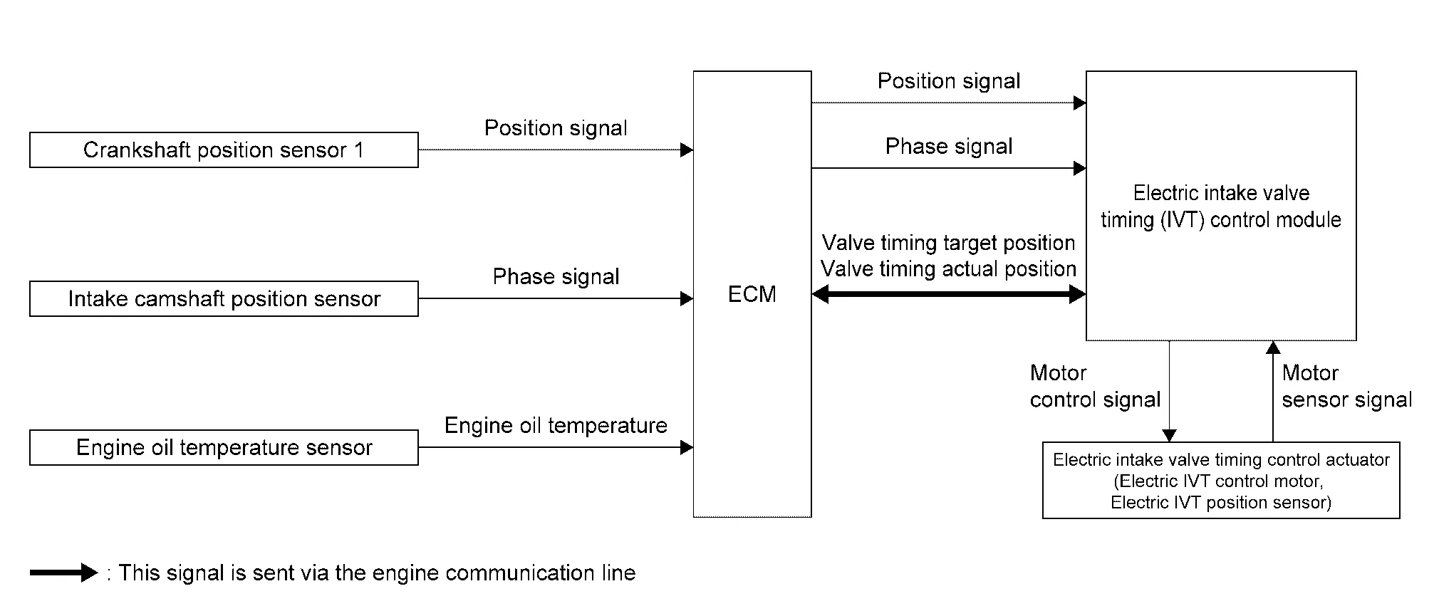
SYSTEM DESCRIPTION
This engine uses an electric VTC. The electric VTC responds faster than hydraulic VTC and allows operating under low engine speed condition. This improves the fuel economy, engine output, and exhaust performance.
This mechanism continuously controls the phase of camshaft by the electric intake valve timing (IVT) control actuator with the amount of intake valve operation held constant.
ECM transmits a crankshaft position signal and an intake camshaft position signal to the electric IVT control module and transmits target values of electric IVT control actuator via engine communication (CAN).
The electric IVT control module controls the electric IVT control actuator according to a signal from ECM and changes the opening and closing timing of intake valve. Furthermore, the electric IVT control actuator has a diagnostic function and transmits a DTC detection signal to ECM via engine communication when detecting a system error.
| Status of electric intake valve timing control actuator | Electric intake valve timing control actuator activation |
|---|---|
| Advanced angle | Electric IVT control motor rotates faster than camshaft. This allows the camshaft position (cam phase) against camshaft sprocket to move toward the advanced angle. |
| Maintained | Electric IVT control motor and camshaft rotate at the same speed. |
| Retard angle | Electric IVT control motor rotates slower than camshaft. This allows the camshaft position (cam phase) against camshaft sprocket to move toward the retard angle. |
Exhaust Valve Timing Control
System Description
SYSTEM DIAGRAM
| Component parts | Function |
|---|---|
| Crankshaft position sensor 1 | Crankshaft Position Sensor 1 |
| Exhaust camshaft position sensor | Exhaust Camshaft Position Sensor |
| Engine oil temperature sensor | Engine Oil Temperature Sensor |
| Combination meter | ECM receives the Nissan Pathfinder vehicle speed signal via CAN communication. |
| ECM | ECM (With Barometric Pressure Sensor) |
| Exhaust valve timing control solenoid valve | Exhaust Valve Timing Control Solenoid Valve |
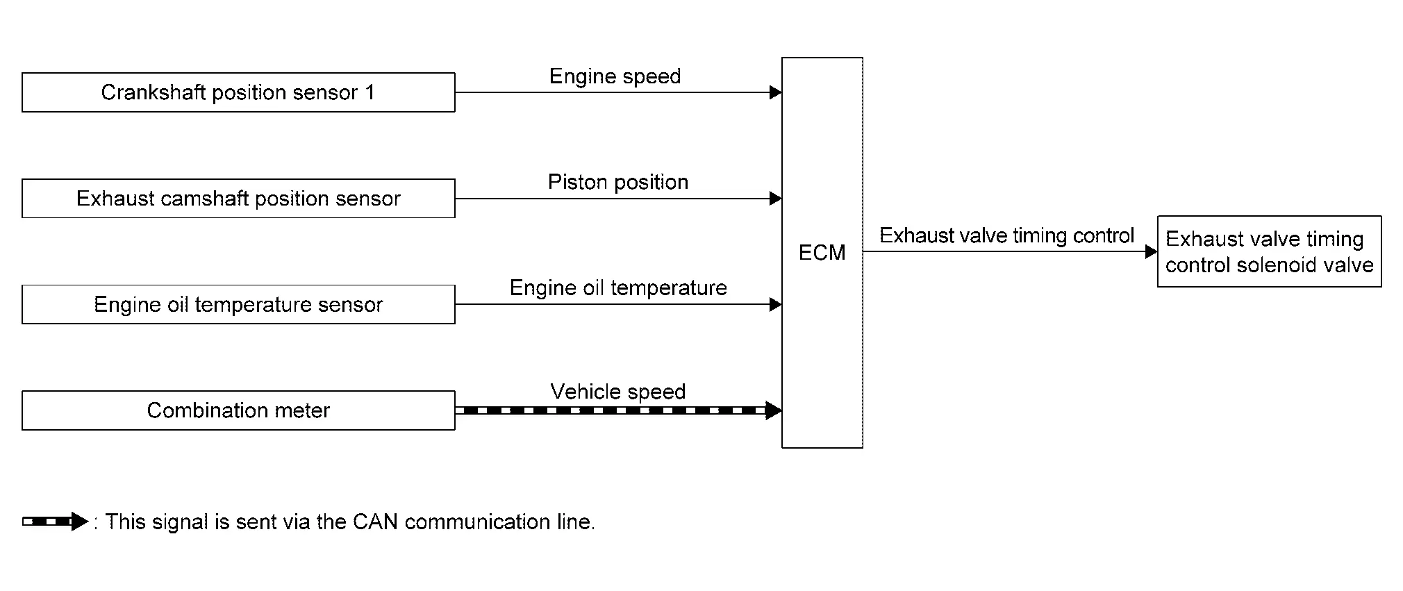
SYSTEM DESCRIPTION
With the exhaust valve timing controller which controls the phase of exhaust camshaft to optional position continuously, ECM improves both low-middle speed torque and high speed performance, emission and fuel efficiency by optimizing the exhaust valve open/close timing according to driving conditions.
The exhaust valve timing controller is hydraulically controlled by the exhaust valve timing control solenoid valve.
This mechanism hydraulically controls cam phases continuously with the fixed operating angle of the exhaust valve.
The ECM receives signals such as crankshaft position, camshaft position, engine speed, and engine oil temperature. Then, the ECM sends ON/OFF pulse duty signals to the exhaust valve timing control solenoid valve depending on driving status. This makes it possible to control the shut/open timing of the exhaust valve to increase engine torque and output in a range of high engine speed.
EXHAUST VALVE TIMING CONTROL SOLENOID VALVE CONTROL
The exhaust valve timing control solenoid valve is driven ON-OFF (duty control) by ECM output signal, and controls the open/close timing of the exhaust valve to the optimum by changing its duty ratio according to the Nissan Pathfinder vehicle's driving condition.
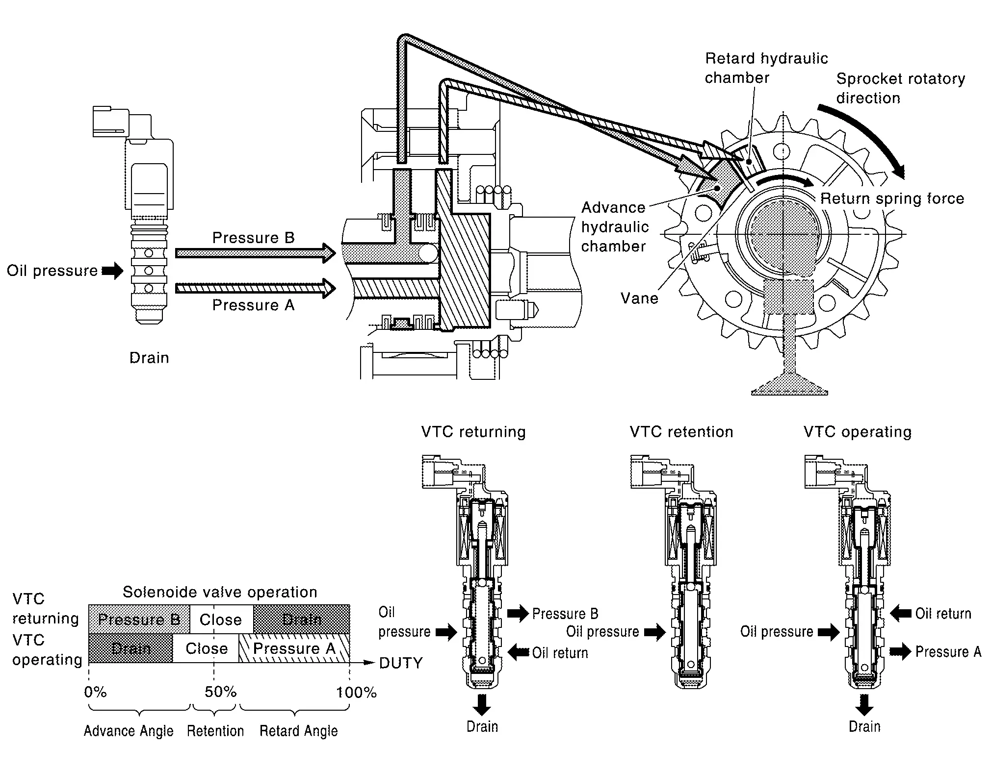
| Exhaust valve timing control solenoid valve condition | Exhaust valve timing controller operation |
|---|---|
| Engine OFF | When starting the engine, the controller vane and sprocket are fixed in full advanced position by the reaction force of return spring, improving the starting performance of the engine. |
| Active (Retard angle) | When the energization rate to the control solenoid valve is increased, the oil pressure from the oil pump is conveyed to the retard angle chamber of the controller. And advanced angle chamber oil is drained. Accordingly, the controller vane rotates leftward and the phase of camshaft becomes retard angle. This condition brings about the greater overlap with the intake valve, enabling the exhaust gas cleaning by the internal EGR effect and the fuel consumption improvement by the reduction in pumping loss. |
| Neutral (Maintained) | When it is the target valve timing, the energization rate to the control solenoid valve is adjusted to the intermediate state. The solenoid valve is positioned at the neutral position and the oil path is interrupted to maintain the cam shaft phase. |
| Return (Advanced angle) | When the energization rate to the control solenoid valve is decreased, the oil pressure from the oil pump is conveyed to the advanced chamber of the controller. And retard angle chamber oil is drained. Accordingly, the controller vane rotates rightward and the phase of camshaft becomes advanced angle. |
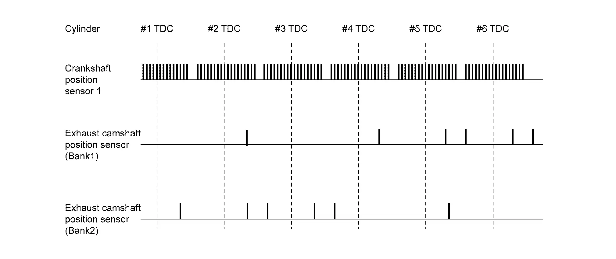
EXHAUST VALVE TIMING CONTROL FEEDBACK CONTROL
Cam Position Detection
The exhaust camshaft position sensor detects a cam position, by using the groove on the plate located at the rear of the exhaust camshaft.
Feedback Control
The exhaust camshaft position sensor feeds back an actual cam position signal to ECM. Based on the signal, ECM controls the exhaust valve timing control solenoid valve to satisfy the optimum target valve opening/closing timing according to a driving condition.
Air Conditioning Cut Control
System Description
SYSTEM DIAGRAM
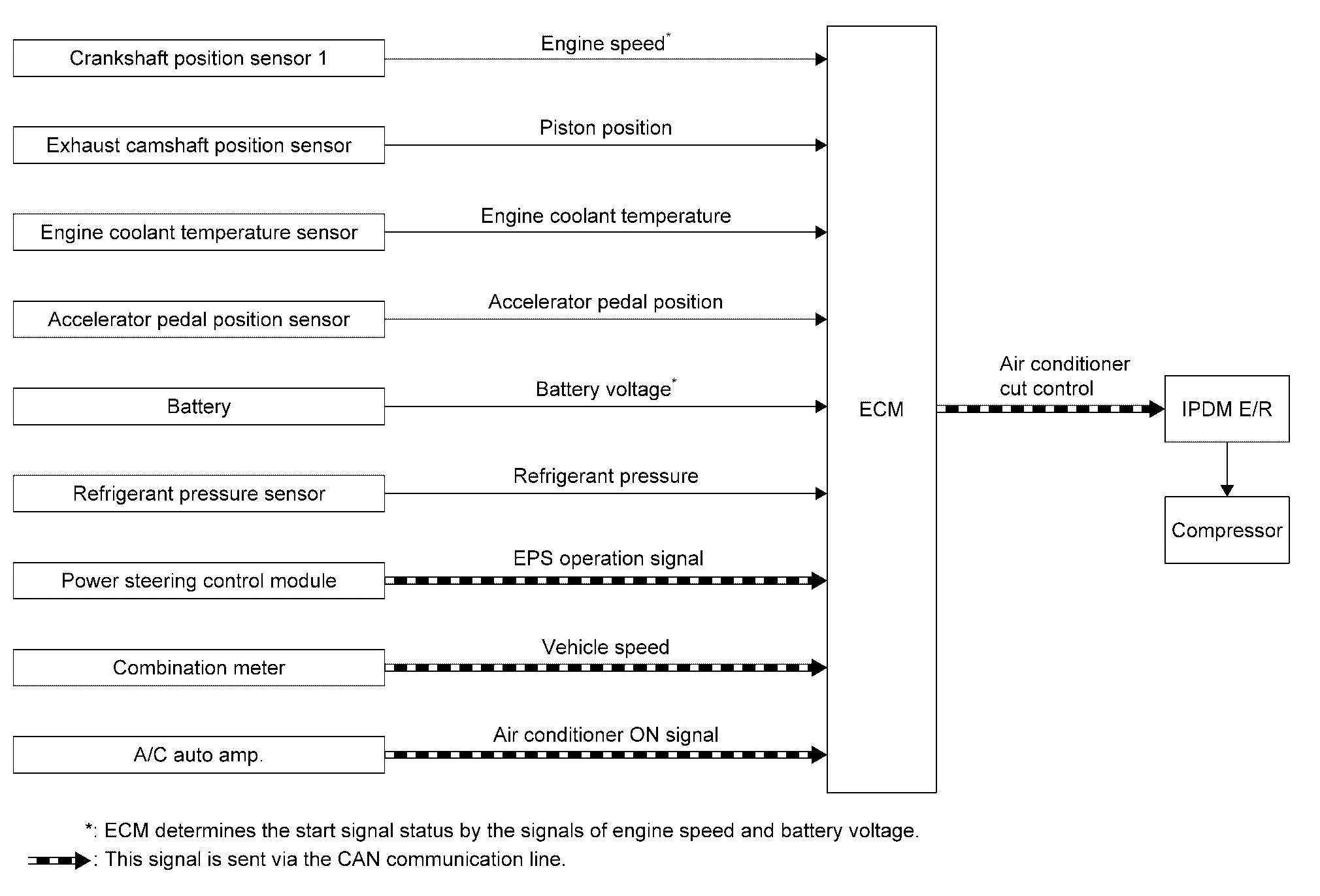
Exhaust camshaft position sensor is not used for engine control operation.
| Component parts | Function |
|---|---|
| Crankshaft position sensor 1 | Crankshaft Position Sensor 1 |
| Exhaust camshaft position sensor | Exhaust Camshaft Position Sensor |
| Engine coolant temperature sensor | Engine Coolant Temperature Sensor |
| Accelerator pedal position sensor | Accelerator Pedal Position Sensor |
| Battery | ECM receives the battery voltage signal. |
| Refrigerant pressure sensor | Refrigerant Pressure Sensor |
| Heated oxygen sensor 2 | Heated Oxygen Sensor 2 |
| Power steering control module | ECM receives the EPS operation signal via CAN communication. |
| Combination meter | ECM receives the Nissan Pathfinder vehicle speed signal via CAN communication. |
| A/C auto amp. | ECM receives the A/C ON signal via CAN communication. |
| ECM | ECM (With Barometric Pressure Sensor) |
| IPDM E/R | ECM transmits the air conditioner cut control signal via CAN communication. |
| Compressor | A/C Compressor |
SYSTEM DESCRIPTION
This system improves engine operation when the air conditioner is used.
Under the following conditions, the air conditioner is turned off.
-
When the accelerator pedal is fully depressed.
-
When cranking the engine.
-
At high engine speeds.
-
When the engine coolant temperature becomes excessively high.
-
When operating power steering during low engine speed or low Nissan Pathfinder vehicle speed.
-
When engine speed is excessively low.
-
When refrigerant pressure is excessively low or high.
Engine Oil Pressure Control System
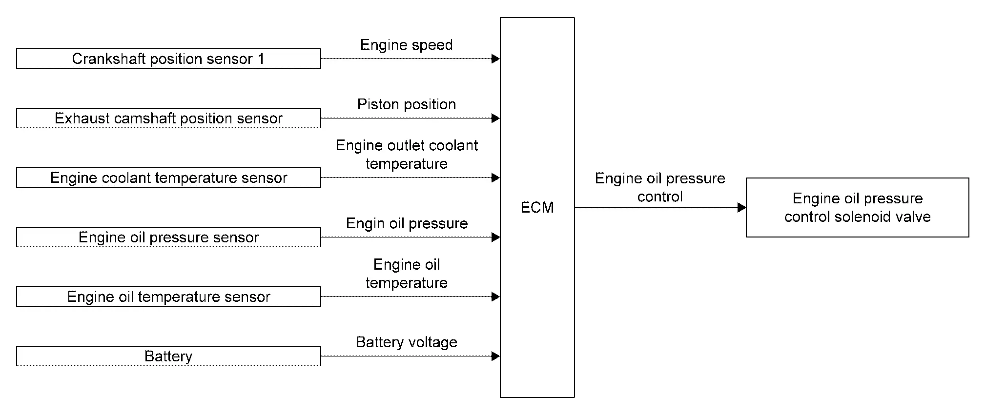
System Description
SYSTEM DIAGRAM
| Component parts | Function |
|---|---|
| Crankshaft position sensor 1 | Crankshaft Position Sensor 1 |
| Exhaust camshaft position sensor | Exhaust Camshaft Position Sensor |
| Engine coolant temperature sensor | Engine Coolant Temperature Sensor |
| Engine oil pressure sensor | Engine Oil Pressure Sensor |
| Engine oil temperature sensor | Engine Oil Temperature Sensor |
| Battery | ECM receives the battery voltage signal. |
| ECM | ECM (With Barometric Pressure Sensor) |
| Engine oil pressure control solenoid valve | Engine Oil Pressure Control Solenoid Valve |
SYSTEM DESCRIPTION
ECM performs the variable hydraulic control (low oil pressure control and high oil pressure control) based on signals from each sensor according to oil temperature and engine load. ECM activates the engine oil pressure control solenoid valve and switches to the low oil pressure control and high oil pressure control. ECM uses the low oil pressure control for 80-90% of the operating area to maintain low oil pressure and stops piston cooling jet (i.e. achievement of less than or equal to jet injection valve opening pressure).
High oil pressure control start condition
-
High oil pressure control start condition
-
High engine speed
-
Coolant temperature is 60°C (140°F) or more under high engine load condition
Low oil pressure control start condition
-
Coolant temperature is less than 60°C (140°F) under low engine speed condition
-
Coolant temperature is 60°C (140°F) or more under low engine load and low engine speed conditions
Engine Protection Control at Low Engine Oil Pressure
System Description
SYSTEM DIAGRAM
| Component parts | Function |
|---|---|
| Engine oil pressure sensor | Engine Oil Pressure Sensor |
| Crankshaft position sensor 1 | Crankshaft Position Sensor 1 |
| Engine oil temperature sensor | Engine Oil Temperature Sensor |
| ECM | ECM (With Barometric Pressure Sensor) |
| Combination meter | It receives the engine oil pressure waning lamp signal from ECM via CAN communication. |
SYSTEM DESCRIPTION
-
The engine protection control at low engine oil pressure warns the driver of a decrease in engine oil pressure by the oil pressure warning lamp before the engine becomes damaged.
-
When detecting a decrease in engine oil pressure at an engine speed less than 1,000 rpm, ECM transmits an oil pressure warning lamp signal to the combination meter. The combination meter turns ON the oil pressure warning lamp, according to the signal.
-
When detecting a decrease in engine oil pressure at an engine speed 1,000 rpm or more, ECM transmits an oil pressure warning lamp signal to the combination meter.
The combination meter turns ON the oil pressure warning lamp, according to the signals. When detecting a decrease in engine oil pressure, ECM cuts fuel if the engine speed exceeds the specified value.
| Decrease in engine oil pressure | Engine speed | Combination meter | Fuel cut |
|---|---|---|---|
| Oil pressure warning lamp | |||
| Detection | Less than 1,000 rpm | ON* | NO |
| 1,000 rpm or more | ON | YES |
*: When detecting a normal engine oil pressure, ECM turns OFF the oil pressure warning lamp.
Cooling System
System Description
SYSTEM DIAGRAM
| Component parts | Function |
|---|---|
| Crankshaft position sensor 1 | Crankshaft Position Sensor 1 |
| Exhaust camshaft position sensor | Exhaust Camshaft Position Sensor |
| Engine coolant temperature sensor | Engine Coolant Temperature Sensor |
| Refrigerant pressure sensor | Refrigerant Pressure Sensor |
| Battery | ECM receives the battery voltage signal. |
| Combination meter | ECM receives the Nissan Pathfinder vehicle speed signal via CAN communication. |
| A/C auto amp. |
ECM receives below signal via CAN communication.
|
| ECM | ECM (With Barometric Pressure Sensor) |
| IPDM E/R | ECM transmits the cooling fan speed request signal via CAN communication. |
| Cooling fan control module | Cooling Fan |
| Cooling fan motor |
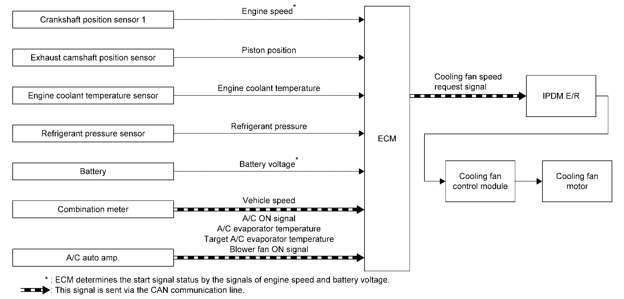
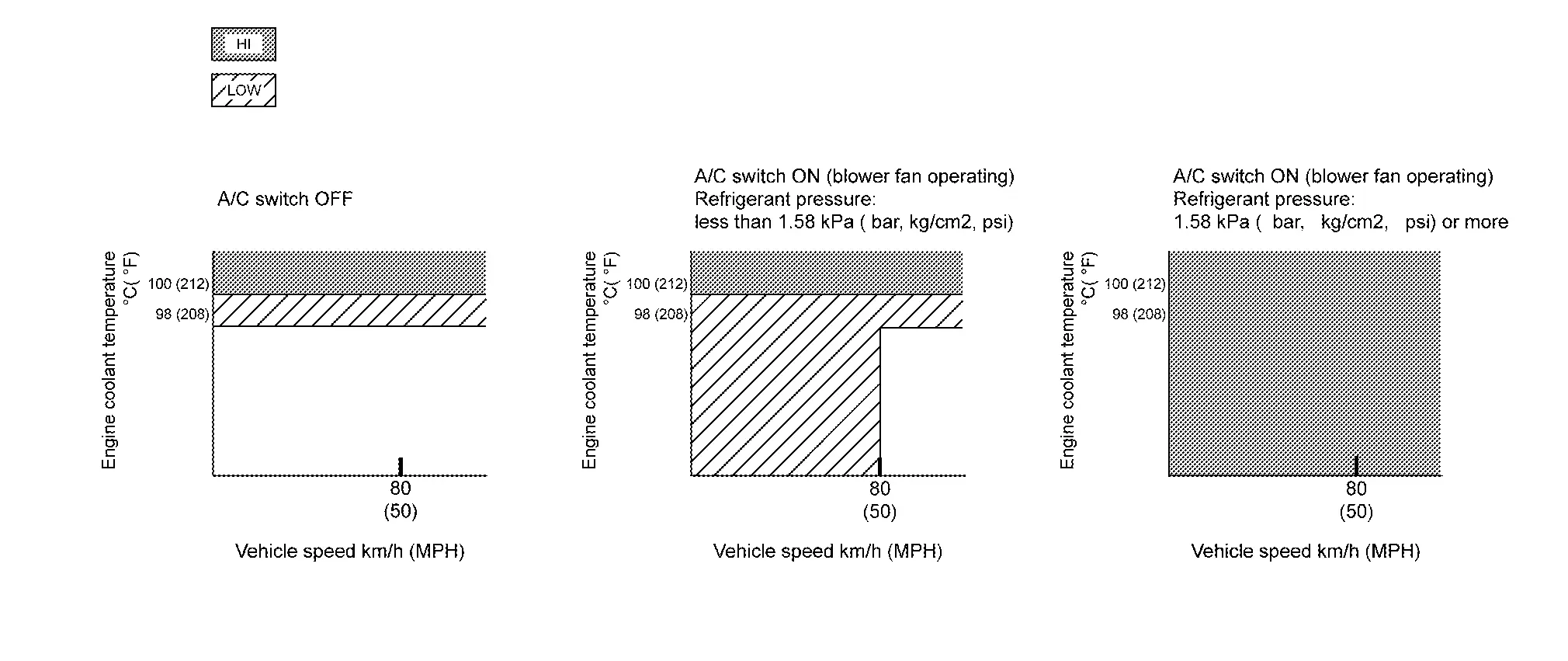
SYSTEM DESCRIPTION
ECM controls cooling fan speed corresponding to vehicle speed, engine coolant temperature, air conditioner ON signal, refrigerant pressure, target A/C evaporator temperature, and A/C evaporator temperature.
Cooling fan speed request signal is sent to IPDM E/R from ECM by CAN communication line. Then, IPDM E/R sends ON/OFF pulse duty signal to cooling fan control module. Corresponding to this ON/OFF pulse duty signal, cooling fan control module gives cooling fan motor operating voltage to cooling fan motors. Cooling fan speed is controlled by duty cycle of cooling fan motor operating voltage sent from cooling fan control module.
Electronic Controlled Engine Mount
System Description
SYSTEM DIAGRAM
| Component parts | Function |
|---|---|
| Crankshaft position sensor 1 | Crankshaft Position Sensor 1 |
| Intake camshaft position sensor | Intake Camshaft Position Sensor |
| Combination meter | ECM receives the Nissan Pathfinder vehicle speed signal via CAN communication. |
| ECM | ECM (With Barometric Pressure Sensor) |
| Engine mount control solenoid valve | Electronic Controlled Engine Mount |
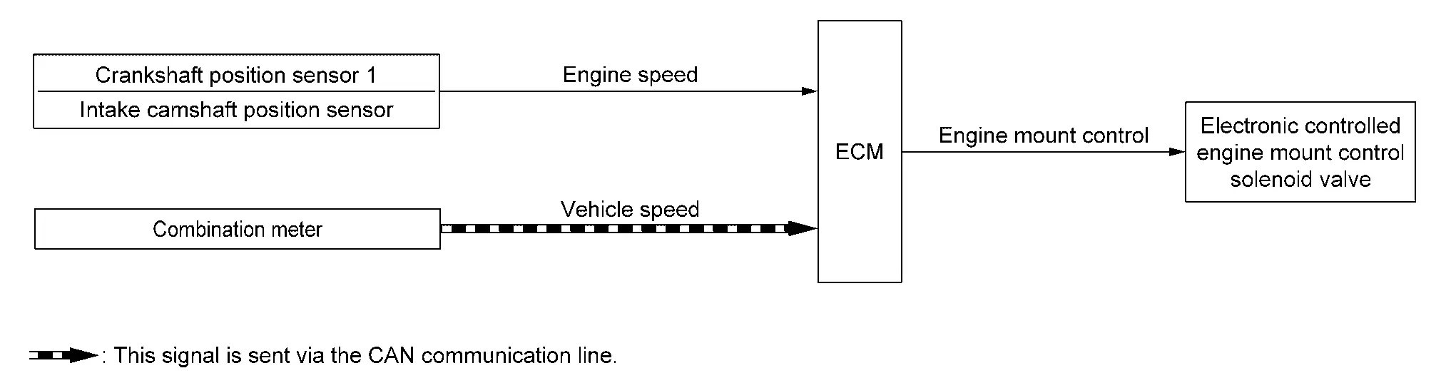
SYSTEM DESCRIPTION
The ECM controls the engine mount operation corresponding to the engine speed. The control system has a 2-step control [Soft/Hard]
| Vehicle condition | Engine mount control |
|---|---|
| Engine speed: Below 950 rpm | Soft |
| Engine speed: Above 950 rpm | Hard |
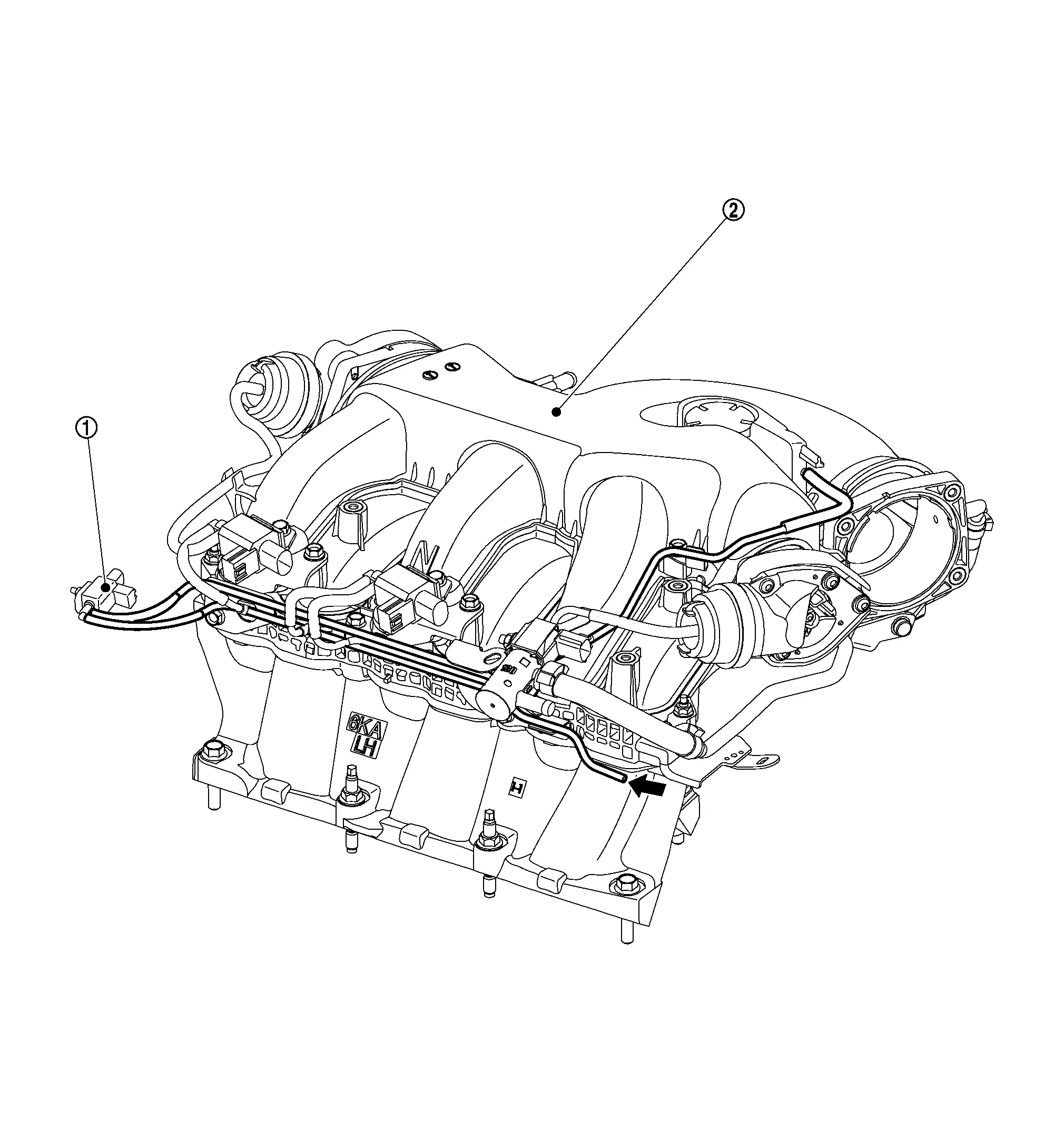
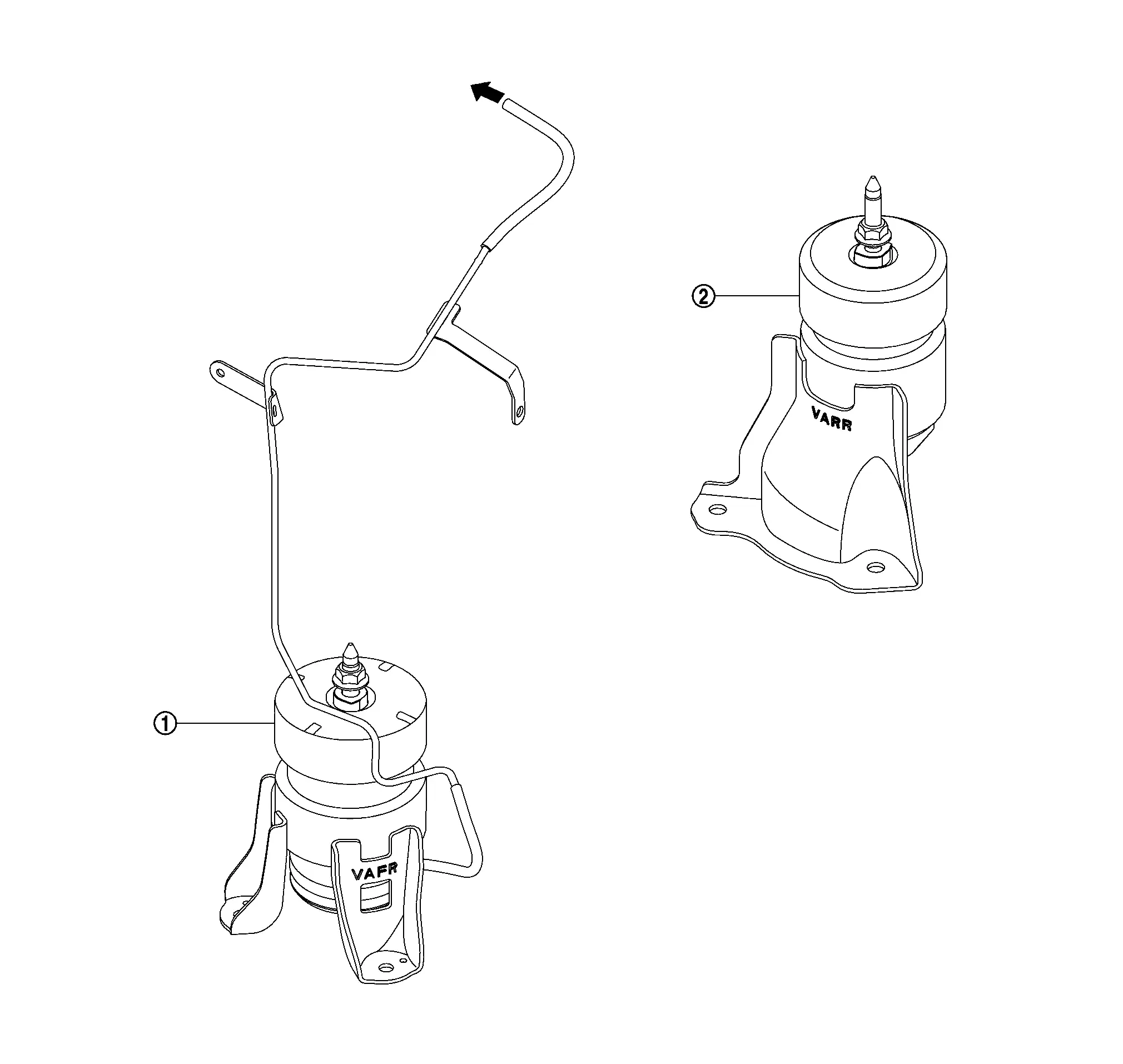
ELECTRONIC CONTROLLED ENGINE MOUNT LINE DRAWING
 |
Electronic controlled engine mount control solenoid valve |
 |
Intake manifold collector | ||
 |
: From next figure |
 |
Front electronic controlled engine mount |
 |
Rear electronic controlled engine mount | ||
 |
: To previous figure |
 NOTE:
NOTE:
Do not use soapy water or any type of solvent while installing vacuum hose.
Evaporative Emission System
System Description
SYSTEM DIAGRAM
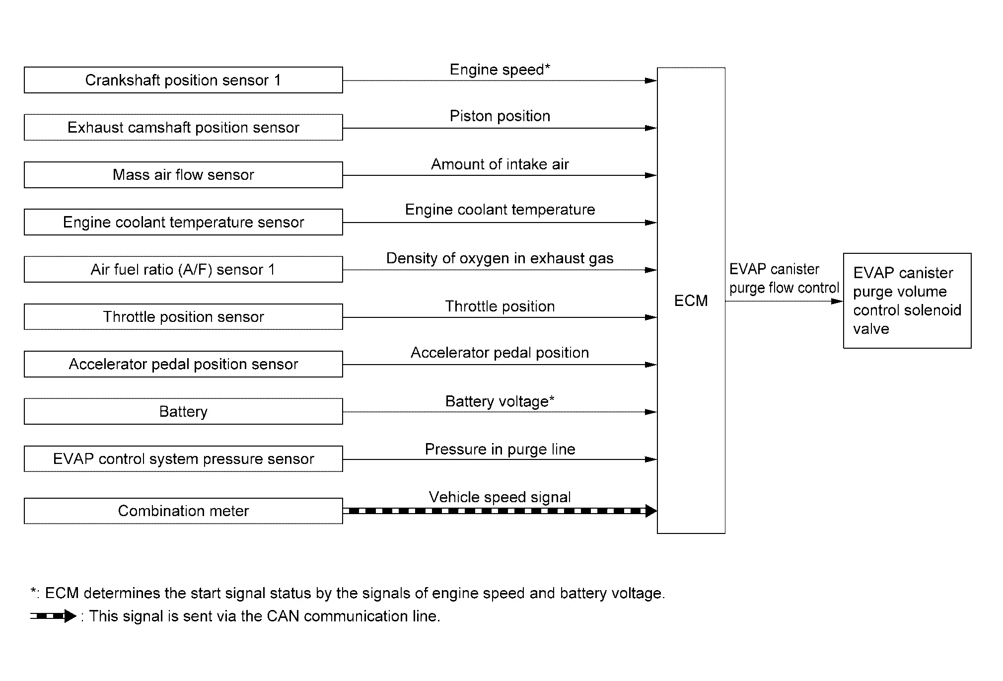
| Component parts | Function |
|---|---|
| Crankshaft position sensor 1 | Crankshaft Position Sensor 1 |
| Exhaust camshaft position sensor | Exhaust Camshaft Position Sensor |
|
Mass air flow sensor (With intake air temperature sensor) |
Mass Air Flow Sensor (With Intake Air Temperature Sensor) |
| Engine coolant temperature sensor | Engine Coolant Temperature Sensor |
| Air fuel ratio (A/F) sensor 1 | Air Fuel Ratio (A/F) Sensor 1 |
| Throttle position sensor | Electric Throttle Control Actuator |
| Accelerator pedal position sensor | Accelerator Pedal Position Sensor |
| Battery | ECM receives the battery voltage signal. |
| EVAP control system pressure sensor | EVAP Control System Pressure Sensor |
| Combination meter | ECM receives the Nissan Pathfinder vehicle speed signal via CAN communication. |
| ECM | ECM (With Barometric Pressure Sensor) |
| EVAP canister purge volume control solenoid valve | EVAP Canister Purge Volume Control Solenoid Valve |
SYSTEM DESCRIPTION
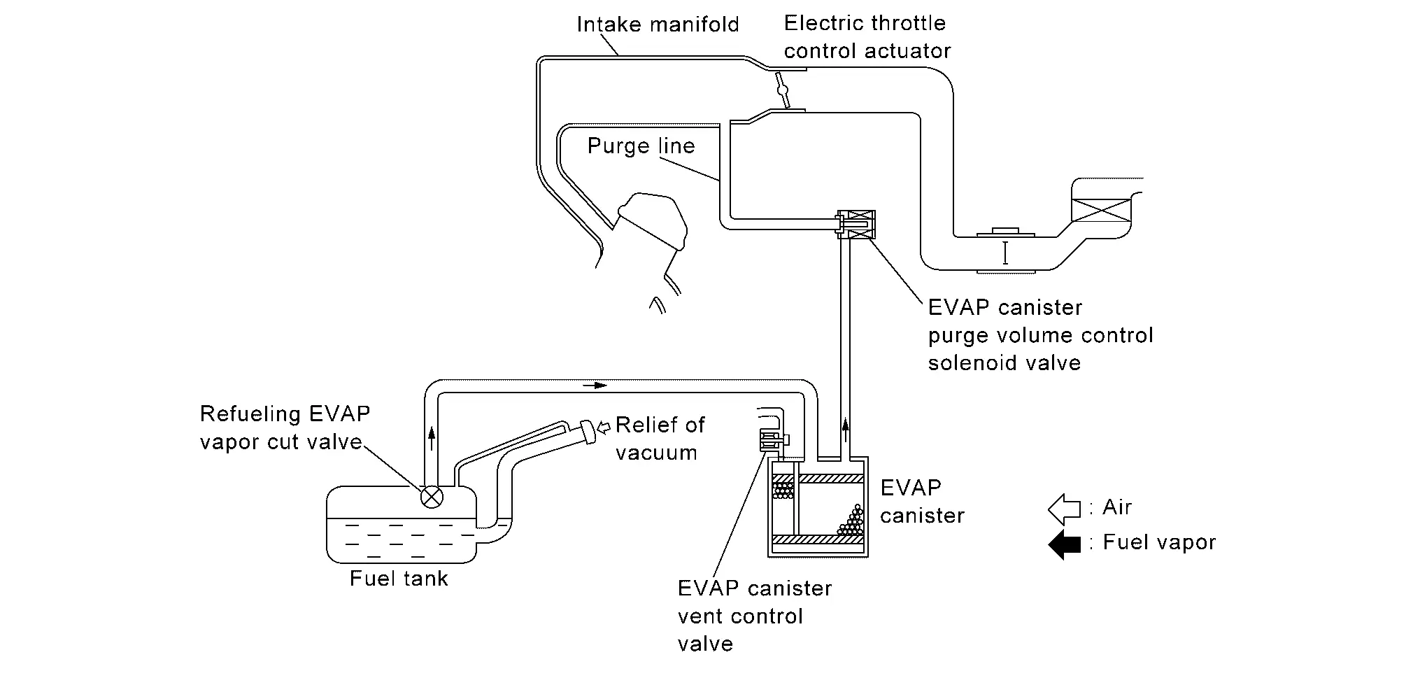
The evaporative emission system is used to reduce hydrocarbons emitted into the atmosphere from the fuel system. This reduction of hydrocarbons is accomplished by activated charcoals in the EVAP canister.
The fuel vapor in the sealed fuel tank is led into the EVAP canister which contains activated carbon and the vapor is stored there when the engine is not operating or when refueling to the fuel tank.
The vapor in the EVAP canister is purged by the air through the purge line to the intake manifold when the engine is operating. EVAP canister purge volume control solenoid valve is controlled by ECM. When the engine operates, the flow rate of vapor controlled by EVAP canister purge volume control solenoid valve is proportionally regulated as the air flow increases.
EVAP canister purge volume control solenoid valve also shuts off the vapor purge line during decelerating and idling.
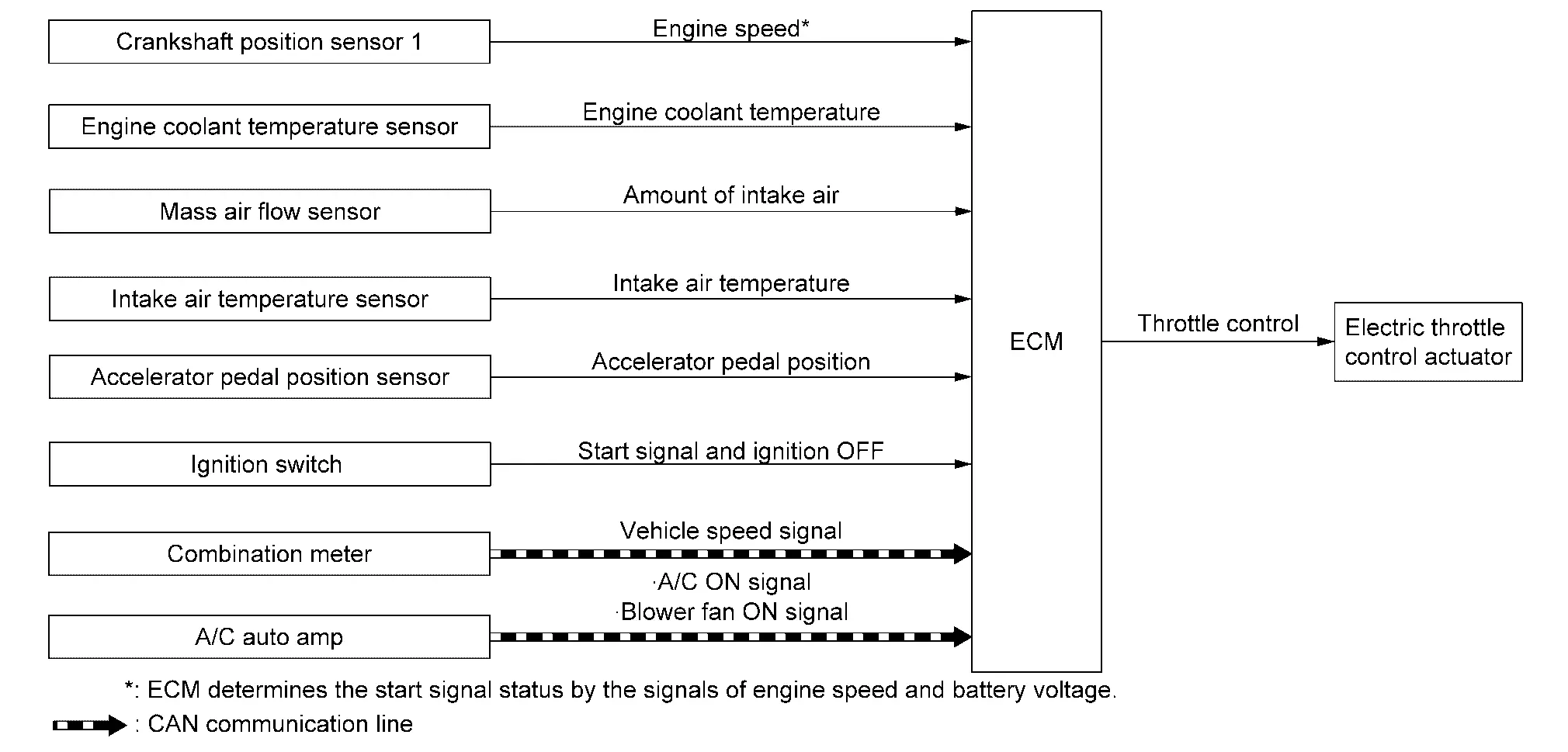
Throttle Control
System Description
SYSTEM DIAGRAM
| Component parts | Function |
|---|---|
| Crankshaft position sensor 1 | Crankshaft Position Sensor 1 |
| Engine coolant temperature sensor | Engine Coolant Temperature Sensor |
| Exhaust camshaft position sensor | Exhaust Camshaft Position Sensor |
|
Mass air flow sensor (With intake air temperature sensor) |
Mass Air Flow Sensor (With Intake Air Temperature Sensor) |
| Intake air temperature sensor | Mass Air Flow Sensor (With Intake Air Temperature Sensor) |
| Accelerator pedal position sensor | Accelerator Pedal Position Sensor |
| Ignition switch | ECM receives the ignition start signal and OFF signal. |
| Combination meter | ECM receives the Nissan Pathfinder vehicle speed signal via CAN communication. |
| A/C auto amp. |
ECM receives below signal via CAN communication.
|
| ECM | ECM (With Barometric Pressure Sensor) |
| Electric throttle control actuator | Electric Throttle Control Actuator |
SYSTEM DESCRIPTION
ECM calculates the value of signal transmitted from the accelerator pedal and activates the throttle valve by transmitting a control signal to the electric throttle control actuator. This allows the optimum throttle angle and improves drivability and fuel consumption. In addition, ECM learns the fully closed position every time when the ignition switch is turned OFF to improve the accuracy in throttle valve position.
When a malfunction occurs in the throttle control system, the throttle valve is closed by the return spring and maintains the minimum engine speed by holding a slightly opened condition which is close to the fully opened condition. This allows the securing of brake system, power steering system, and electric system and the ensuring of the safety.
Variable Induction Air System
System Description
SYSTEM DIAGRAM
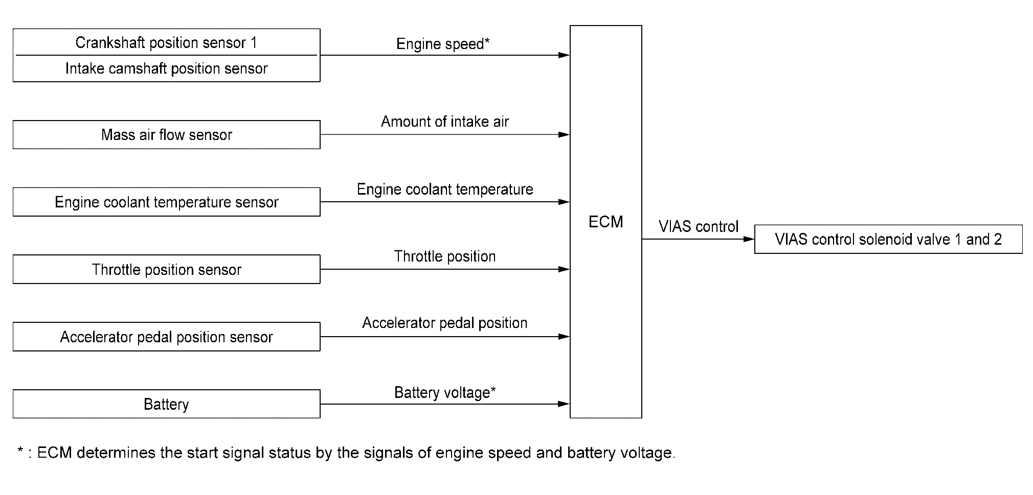
| Component parts | Function |
|---|---|
| Crankshaft position sensor 1 | Crankshaft Position Sensor 1 |
| Intake camshaft position sensor | Intake Camshaft Position Sensor |
|
Mass air flow sensor (With intake air temperature sensor) |
Mass Air Flow Sensor (With Intake Air Temperature Sensor) |
| Engine coolant temperature sensor | Engine Coolant Temperature Sensor |
| Throttle position sensor | Electric Throttle Control Actuator |
| Accelerator pedal position sensor | Accelerator Pedal Position Sensor |
| Battery | ECM receives the battery voltage signal. |
| ECM | ECM (With Barometric Pressure Sensor) |
| VIAS control solenoid valve 1 and 2 | VIAS Control Solenoid Valve 1 and 2 |
SYSTEM DESCRIPTION
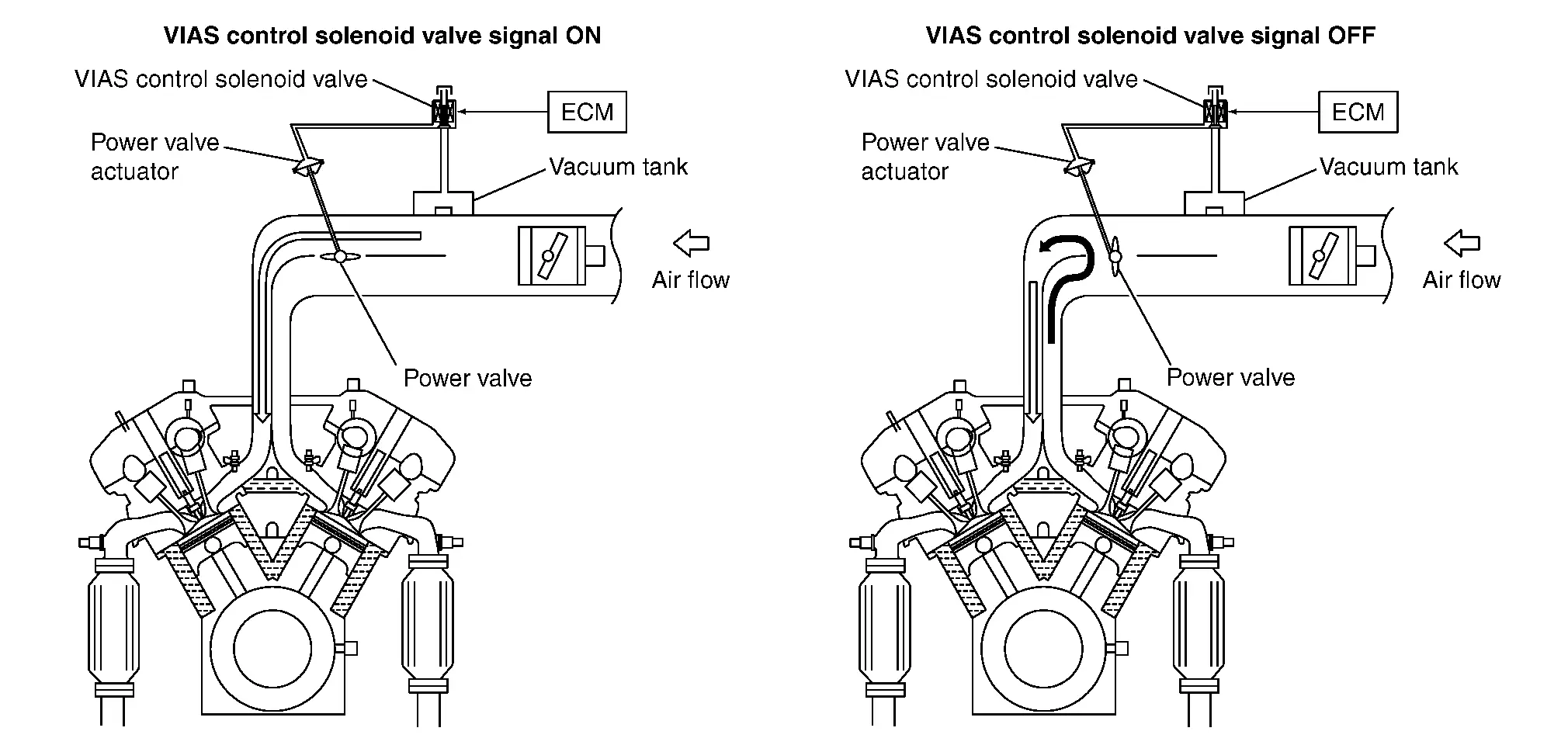
In the medium speed range, the ECM sends the ON signal to the VIAS control solenoid valve. This signal introduces the intake manifold vacuum into the power valve actuator and therefore closes the power valve. Under this condition, the pressure waves of the exhaust stroke do not disturb the pressure waves of the intake stroke of each opposite bank. Therefore, charging efficiency is increased together with the effect of the long intake passage.
However, in the high speed range, the ECM sends the OFF signal to the VIAS control solenoid valve and the power valve is opened. Under this condition, the pressure waves of intake stroke are resonant with those of each opposite bank exhaust stroke. Therefore, charging efficiency is also increased.
In addition, both valves 1 and 2 are opened or closed in other ranges mentioned above. Thus maximum charging efficiency is obtained for the various driving conditions.
VACUUM HOSE DRAWING
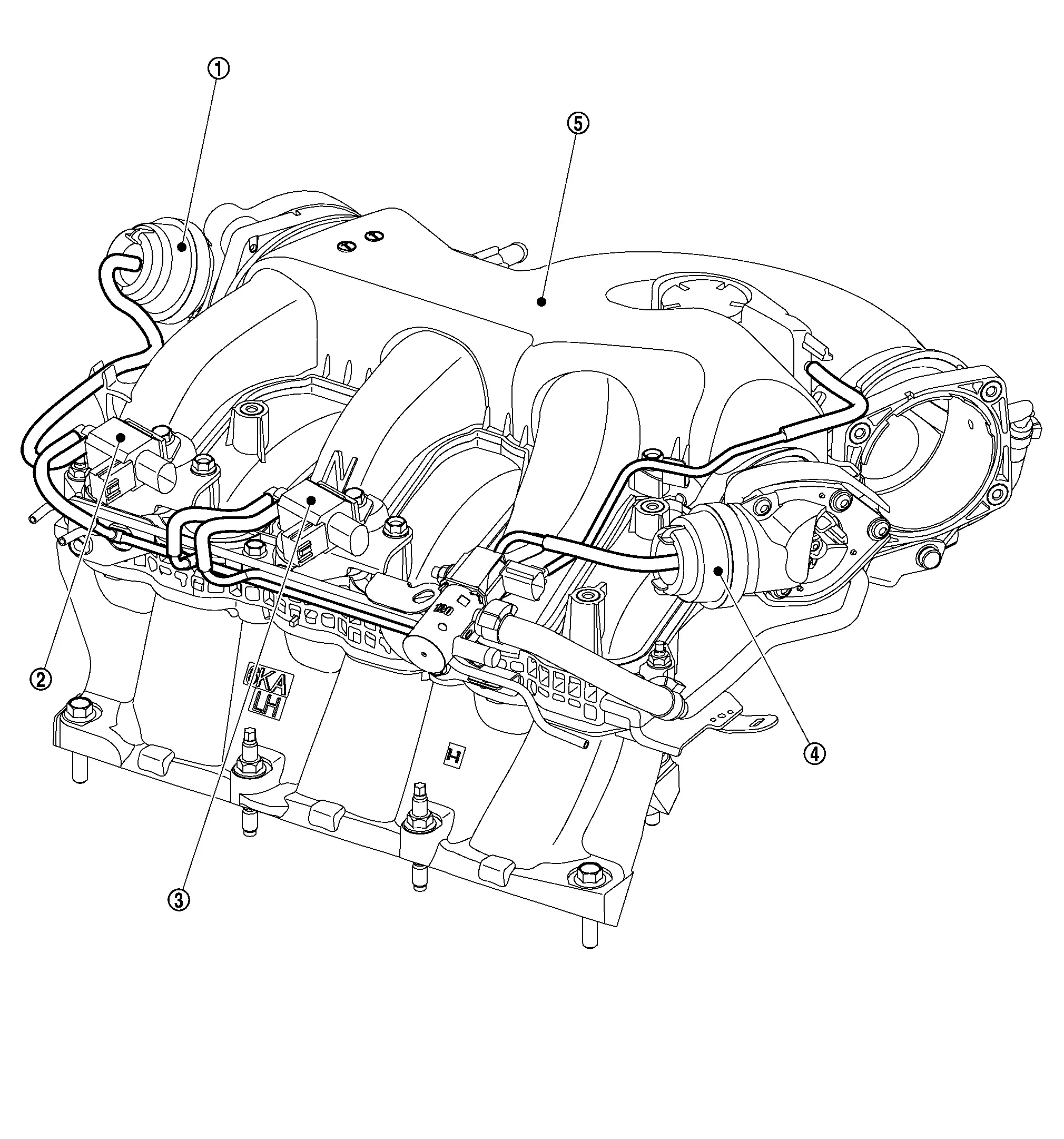
 |
Power valve actuator 1 |
 |
VIAS control solenoid valve 1 |
 |
VIAS control solenoid valve 2 |
 |
Power valve actuator 2 |
 |
Intake manifold collector |
Automatic Speed Control Device (ascd)
System Description
SYSTEM DIAGRAM
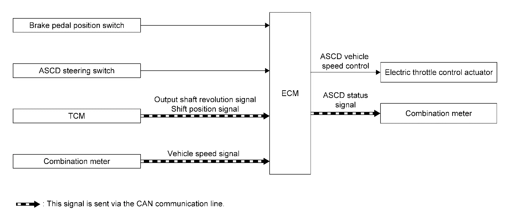
| Component parts | Function |
|---|---|
| Brake pedal position switch | Stop Lamp Switch Brake Pedal Position Switch |
| ASCD steering switch | ASCD Steering Switch |
| TCM |
ECM receives the following signals via CAN communication.
|
| Combination meter |
|
| ECM | ECM (With Barometric Pressure Sensor) |
| Electric throttle control actuator | Electric Throttle Control Actuator |
BASIC ASCD SYSTEM
Refer to Owner's Manual for ASCD operating instructions.
Automatic Speed Control Device (ASCD) allows a driver to keep vehicle at predetermined constant speed without depressing accelerator pedal. Driver can set Nissan Pathfinder vehicle speed in advance between approximately 40 km/h (25 MPH) and 144 km/h (89 MPH).
ECM controls throttle angle of electric throttle control actuator to regulate engine speed.
Operation status of ASCD is indicated by CRUISE indicator and SET indicator in combination meter. If any malfunction occurs in the ASCD system, it automatically deactivates control.
 NOTE:
NOTE:
Always drive vehicle in a safe manner according to traffic conditions and obey all traffic laws.
SET OPERATION
Press MAIN switch. (The CRUISE indicator in combination meter illuminates.)
When vehicle speed reaches a desired speed between approximately 40 km/h (25 MPH) and 144 km/h (89 MPH), press COAST/SET switch. (Then SET lamp in combination meter illuminates.)
ACCELERATE OPERATION
If the ACCEL/RES switch is pressed during cruise control driving, increase the vehicle speed until the switch is released or Nissan Pathfinder vehicle speed reaches maximum speed controlled by the system.
And then ASCD will maintain the new set speed.
CANCEL OPERATION
When any of following conditions exist, cruise operation will be canceled.
-
CANCEL switch is pressed
-
More than 2 switches at ASCD steering switch are pressed at the same time (Set speed will be cleared)
-
Brake pedal is depressed
-
Selector lever is in the N, P, R position
-
Nissan Pathfinder Vehicle speed decreased to 13 km/h (8 MPH) lower than the set speed
-
TCS system is operated
When the ECM detects any of the following conditions, the ECM will cancel the cruise operation and inform the driver by blinking indicator lamp.
-
Engine coolant temperature is slightly higher than the normal operating temperature, CRUISE lamp may blink slowly.
When the engine coolant temperature decreases to the normal operating temperature, CRUISE lamp will stop blinking and the cruise operation will be able to work by pressing COAST/SET switch or ACCEL/RES switch.
-
Malfunction for some self-diagnoses regarding ASCD control: SET indicator will blink quickly.
If MAIN switch is turned to OFF while ASCD is activated, all of ASCD operations will be canceled and Nissan Pathfinder vehicle speed memory will be erased.
COAST OPERATION
When the COAST/SET switch is pressed during cruise control driving, decrease vehicle set speed until the switch is released. And then ASCD will maintain the new set speed.
RESUME OPERATION
When the ACCEL/RES switch is pressed after cancel operation other than pressing MAIN switch is performed, Nissan Pathfinder vehicle speed will return to last set speed. To resume vehicle set speed, vehicle condition must meet following conditions.
-
Brake pedal is released
-
CVT shift selector lever is in the P and N positions
-
Nissan Pathfinder Vehicle speed is greater than 40 km/h (25 MPH) and less than 144 km/h (89 MPH)
Can Communication
System Description
CAN (Controller Area Network) is a serial communication line for real time application. It is an on-Nissan Pathfinder vehicle multiplex communication line with high data communication speed and excellent error detection ability. Many electronic control units are equipped onto a Nissan Pathfinder vehicle, and each control unit shares information and links with other control units during operation (not independent). In CAN communication, control units are connected with 2 communication lines (CAN H line, CAN L line) allowing a high rate of information transmission with less wiring. Each control unit transmits/receives data but selectively reads required data only.
Refer to CAN Communication Control Circuit, about CAN communication for detail.
Oil Control System
System Description
SYSTEM DIAGRAM
| Component parts | Function |
|---|---|
| Crankshaft position sensor 1 | Crankshaft Position Sensor 1 |
| Engine coolant temperature sensor | Engine Coolant Temperature Sensor |
| Mass Air Flow Sensor (With Intake Air Temperature Sensor) | Mass Air Flow Sensor (With Intake Air Temperature Sensor) |
| ECM | ECM (With Barometric Pressure Sensor) |
| Combination meter |
|
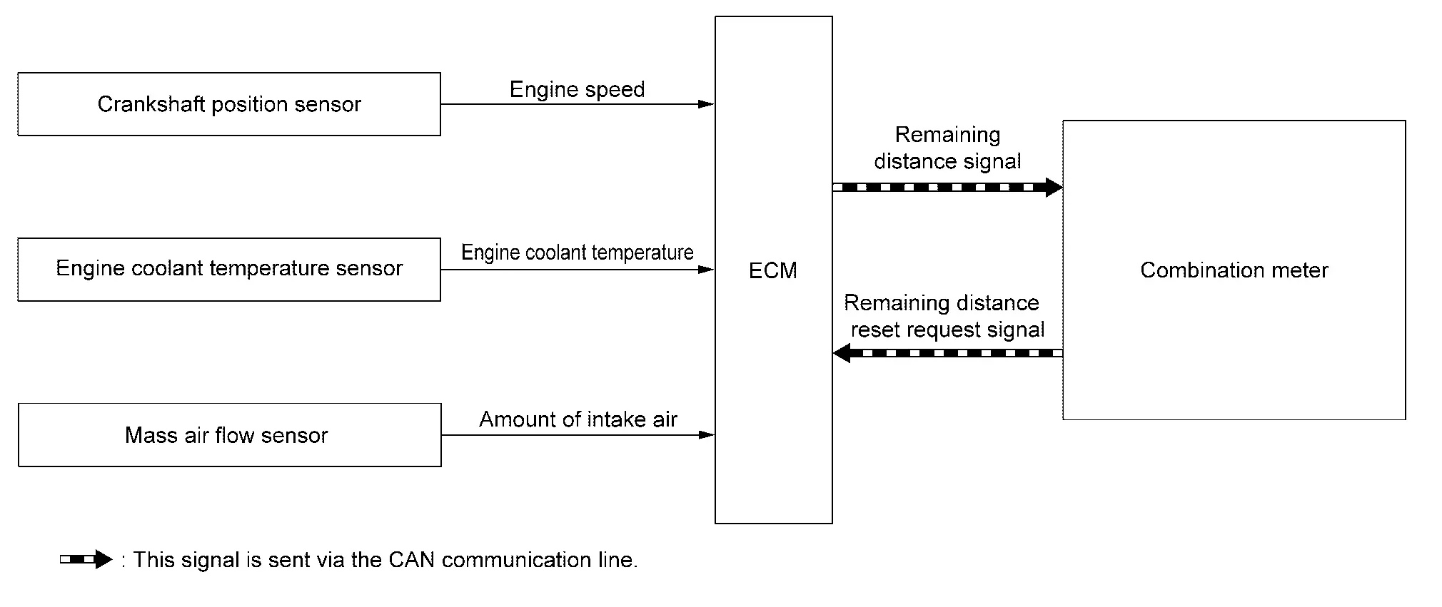
SYSTEM DESCRIPTION
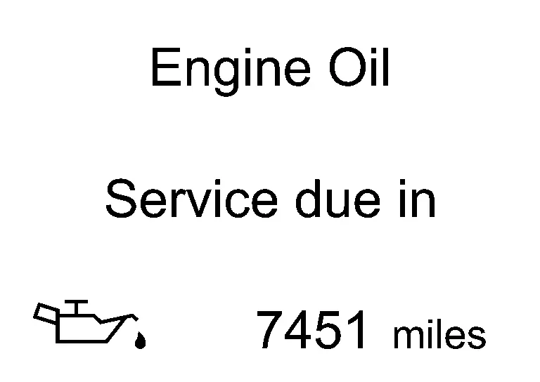
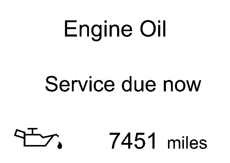
ECM calculates engine load, engine coolant temperature, and engine speed based on signals from the mass air flow sensor, engine coolant temperature sensor, and crankshaft position sensor 1 and monitors the deterioration state of engine oil.
When the mileage before engine oil change comes to approximately 1,500 km or less, pre-alert message is displayed to inform the driver that the maintenance timing is close as shown in the following table.
| Remaining mileage to the engine oil change timing | Alert timing | ||
|---|---|---|---|
| 1,000 km < the mileage ≤ 1,500 km (630 mile <the mileage ≤ 940 mile) | The first IGN ON after reaching 1,500 km (940 mile) | ||
| 500 km < the mileage ≤ 1,000 km (310 mile < the mileage ≤ 630 mile) | The first IGN ON after reaching 1,000 km (630 mile) | ||
| 500 km or less (310 mile or less) | The first IGN ON every 100 km (60 mile) |
Furthermore, when the timing is passed, alert message is displayed every time when ignition switch is turned ON to inform the driver that engine oil change is necessary.
At oil change, the mileage must be reset using vehicle information display function.
 NOTE:
NOTE:
Alerted mileage might be different from actual mileage.
Stop/start System
System Description
SYSTEM DIAGRAM

Electric oil pump is not applied.
INPUT/OUTPUT SIGNAL CHART
| Input/Output | Transmits/Receives component | Signal name | Description | |
|---|---|---|---|---|
| Input | Accelerator pedal position sensor | Accelerator pedal position sensor signal | Detects an accelerator pedal position. | |
| Crankshaft position sensor | Crankshaft position sensor signal | Detects an engine speed. | ||
| Engine coolant temperature sensor | Engine coolant temperature sensor signal | Detects an engine coolant temperature. | ||
| Atmospheric pressure sensor | Atmospheric pressure sensor signal | Detects an atmospheric pressure. | ||
| IPDM E/R | CAN communication | Stop/Start permit signal | Detects the Electric Energy management system is ready to operate the stop/start system. | |
| Hood switch signal | Detects engine hood status. | |||
| Starter status signal | Detects the status of starter | |||
| Starter relay and starter control relay status signal | Detects the status of Starter relay. | |||
| BCM | CAN communication | Stop lamp switch signal | Detects the status of brake pedal switch. | |
| Door switch signal | Detects the status of driver side door. | |||
| Stop/Start OFF switch signal | Detects stop/start OFF switch status. | |||
| I-key exist information signal | Detects the i-key exist | |||
| Driver seatbelt switch malfunction signal | Detects the driver seatbelt switch is malfunction. | |||
| Delivery mode signal | Detects Nissan Pathfinder vehicle is in delivery mode | |||
| Seat belt buckle switch signal | Detects driver is sitting on the driver seat. | |||
| ABS actuator and electric unit (control unit) | CAN communication | Nissan Pathfinder Vehicle speed signal | Detects vehicle speed. | |
| Brake fluid pressure sensor signal | Detects brake fluid pressure. | |||
| ABS operation signal | Detects ABS operation. | |||
| Stop/Start permit signal | Detects the Braking system is ready to operate the stop/start system | |||
| ABS malfunction signal | Detects ABS is malfunction | |||
| Brake booster pressure status signal | Detects the status of brake booster pressure. | |||
| Stand Still Assist signal | Detect the Stand still Assist status. | |||
| Road sloop estimetion signal | Detects Nissan Pathfinder vehicle angularity. | |||
| EPS control unit | CAN communication | EPS torque signal | Detects an operational state of EPS system. | |
| A/C auto amp. | CAN communication | Stop/Start permit signal | Detects the air conditioning system is ready to operate the stop/start system. | |
| Combination meter | CAN communication | Parking brake status signal | Detects the status of parking brake | |
| TCM | CAN communication | Stop/Start permit signal | Detects the transmission is ready to operate the stop/start system. | |
| Shift position signal | Detects the transmission is ready to operate the stop/start system. | |||
| Transmission malfunction signal | Detects Transmission is malfunction. | |||
| Electric parking brake | CAN communication | Stop/Start permit signal | Detects the electrical parking brake status. | |
| ADAS control unit 2 | CAN communication | Stop/Start permit signal | Detects the pro pilot status. | |
| Chassis control module | CAN communication | Drive mode status signal | Detects the drive mode status. | |
| Output | BCM | CAN communication | Stop/Start status signal | Transmits a stop/start status signal |
| ST Cut relay ON request signal | Transmits ST Cut relay ON request according to the stop/start system | |||
| Stop/start switch lamp ON request signal | | Transmits the stop/start switch lamp ON request | |||
| ABS actuator and electric unit (control unit) | CAN communication | Stop/Start status signal | Transmits a stop/start status signal | |
| Brake hold request signal | Transmits the brake hold/release request according to the stop/start system. | |||
| EPS control unit | CAN communication | Stop/Start status signal | Transmits a stop/start status signal | |
| A/C auto amp. | CAN communication | Stop/Start status signal | Transmits a stop/start status signal | |
| TCM | CAN communication | Stop/Start status signal | Transmits a stop/start status signal | |
| Combination meter | CAN communication | Stop/Start indicator lamp and message request signal | Transmits request signal which turns ON the stop/start indicator lamp and display message | |
| Electric parking brake | CAN communication | Stop/Start status signal | Transmit a stop/start status signal. | |
| ADAS control unit 2 | CAN communication | Stop/Start status signal | Transmit a stop/start status signal. | |
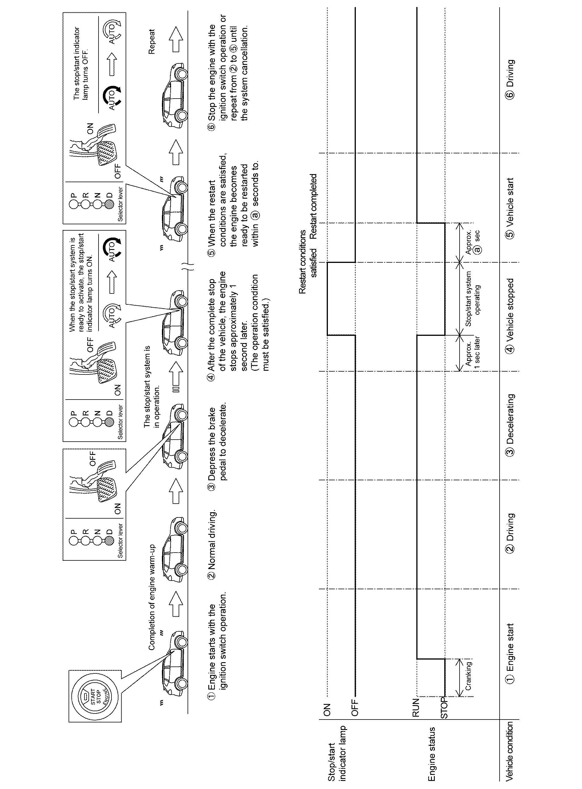
SYSTEM DESCRIPTION
The stop/start system enables the engine to automatically stop/restart with a simple operation and reduces unnecessary idling during stoplight or traffic congestion to improve fuel economy, reduce exhaust gas, and minimize noise.
ECM detects a vehicle condition, engine condition and driver′s operation condition based on signals sent from each unit and the sensors to comprehensively control the stop/start system.
The operation condition of the stop/start system is indicated by the stop/start indicator lamp on the combination meter and showing on the information display. (Refer to Switch Name and Function.) If a malfunction is detected in the stop/start system, the system control is automatically deactivated and the malfunction is alerted to the driver by blinking the stop/start indicator lamp and showing the status on the information display. When a driver′s operation is judged as dangerous one during the stop/start system operation, the stop/start indicator lamp blinks at a high speed and the status is shown on the information display . The buzzer mounted on the combination meter sounds simultaneously to warn the driver of the dangerous operation.
Stop/start indicator lamp status
| System condition | Condition | Stop/start indicator lamp | Warning chime |
|---|---|---|---|
| Operate | Normal | Illuminate | — |
| Hood open | No display | Sound | |
| Fail-Safe | Starter motor operation counter: too much | blinking | — |
| Malfunction of stop/start system | Blinking | — |
 NOTE:
NOTE:
Starting the engine from stop/start system operation is regarded as “Restart”.
BASIC OPERATION
FUNCTION DESCRIPTION
When the stop/start system readiness conditions are satisfied while the vehicle is moving, the system is ready.
When the stop/start system operation conditions are satisfied while the vehicle is in a stop condition, the engine is stopped.
The amount of fuel saved by the stop/start system and CO2 saved information are indicated on the combination meter.
When the engine restart conditions are satisfied, ECM makes IPDM E/R restart the engine.
After restarting the engine, the stop/start indicator lamp and the indication on the information display turn OFF.
Stop/Start Readiness Condition
ECM judges stop/start system is ready when the following conditions are satisfied.
| Item | Condition | ||
|---|---|---|---|
| Nissan Pathfinder Vehicle | Stop/start OFF switch | OFF (Switch indicator: OFF) | |
| Stop/start indicator Lamp | Not blink (No malfunction) | ||
| Door (driver side) | Close | ||
| Seat belt (driver side) | Fastened | ||
| Driving history | Drive the Nissan Pathfinder vehicle at 13 km/h (8 MPH) or more after start the engine with ignition switch | ||
|
Drive the Nissan Pathfinder vehicle at 8 km/h (5 MPH) or more after restart
When shift the selector lever R to D, drive the Nissan Pathfinder vehicle at 10 km/h (6.3 MPH) or more. |
|||
| Passes 5 seconds or more after restart | |||
| Hood | Close | ||
| Air conditioning | Automatic air conditioning | Not in DEF mode | |
| Receives Stop/start permit signal | |||
| Manual air conditioning | Not in DEF mode | ||
| ABS | System is normal | ||
| ABS not activated*2 | |||
| Receives Stop/start permit signal | |||
| EPS | System is normal | ||
| Battery status | Receives Stop/start permit signal from IPDM E/R. | ||
| Gear Position | D position | ||
| I-key | I-key exists inside Nissan Pathfinder vehicle | ||
| ST RLY operation status | Relay operates correctly | ||
| Starter motor | No starter motor long continuous operation | ||
| Delivery mode | Not in delivery mode*2 | ||
| Brake booster pressure | Presence of sufficient negative pressure to a brake force. (Refer to System Description.) | ||
| Stand Still Activation | Receives Stop/Start permit signal. | ||
| Pro pilot | Receives Stop/Start permit signal. | ||
| Intelligent Parking Assist | Receives Stop/Start permit signal. | ||
| Drive mode switch | Detects TOW mode. | ||
 NOTE:
NOTE:
*1: If ABS system is activated, drive the vehicle at 12 km/h (7.5 MPH) or more after stop the vehicle.
*2: No activation in market
CAUTION:
-
The stop/start system may be cancelled when the battery is weak or if a battery other than the stop/start system specific battery is used.
-
Even though the Nissan Pathfinder vehicle is in above conditions, the stop/start system may be cancelled automatically.
Stop/Start Operation Condition
When the following conditions are satisfied, ECM stops the engine. And the combination meter turns ON a stop/start indicator lamp.
| Item | Condition | |
|---|---|---|
| Nissan Pathfinder Vehicle | Vehicle speed | Vehicle stopped [0 km/h (0 MPH)] |
| Steering wheel | Not steer (steering force does not occur) | |
| Brake pedal | Depressed | |
| Brake fluid pressure | 0.6 Mpa (6 bar, 6.12 kg/cm2, 87 psi) | |
| Nissan Pathfinder Vehicle angularity | Approx. 14% or less | |
| ST RLY Cut relay | Close | |
| Engine | Engine speed | Around idle speed (Approx. 1,200 rpm or less) |
| Elevation | 2500 m (8,202 ft) | |
| Engine coolant temperature | 37 - 100℃ (98.6 - 212°F) | |
| Engine system | Permit Stop/start operation | |
| Transmission | Transmission system | Receives Stop/start permit signal |
| Gear position | D position. | |
Restart Condition
When any of the following conditions is satisfied during stop/start system operating condition, ECM restarts the engine. And the combination meter turns OFF the stop/start indicator lamp.
| Item | Condition | ||
|---|---|---|---|
| Stop/Start before Nissan Pathfinder vehicle halt | Stop/Start | ||
| Nissan Pathfinder Vehicle | Stop/start OFF switch | ON (Switch indicator ON) | |
| Door (driver side) | Open | ||
| Seat belt | Released | ||
| I-key | I-key doesn't exist inside Nissan Pathfinder vehicle | ||
| Air conditioning | Auto air conditioning | Select DEF mode | |
| Air conditioning system cannot keep the performance. | |||
| Manual air conditioning | Select DEF mode and fan is ON | ||
| Brake | Brake pedal | Released | |
| Brake pedal negative pressure | Insufficient brake negative pressure | ||
| Accelerator pedal | Depressed | ||
| Engine | Engine coolant temperature | less than 36℃ (96.8°F)、 over than 100℃ (212°F) | |
| Engine system | Inhibit Stop/start operation | ||
| Trans mission | Shift lever position | Except for D position | |
| Paddle shift | Operation | ||
| Battery |
Poor battery performance (for details, refer to System Description.) |
||
| ABS | Receives Stop/start operation | ||
| Intelligent Parking Assist | |||
| Stand Still Assist | |||
| Traffic Jam Pilot | |||
| Emargency brake | |||
| Drive mode switch | Selected the TOW mode | ||
Engine stalled Condition
When any of the following conditions is satisfied during stop/start system operating condition, ECM stalls the engine.
| Item | Condition | |
|---|---|---|
| Nissan Pathfinder Vehicle | Hood | Open |
 NOTE:
NOTE:
-
The engine may restart automatically if required by the Idling Stop System.
-
Place the Ignition switch in the "OFF" position before opening the hood or performing any maintenance. Failure to do so may result in serious injuries due to automatic engine restart.
-
Always place the Ignition switch in the "OFF" position before leaving your vehi-cle, as the system may have turned the engine off, but the Ignition will still be on and automatic restart may occur.
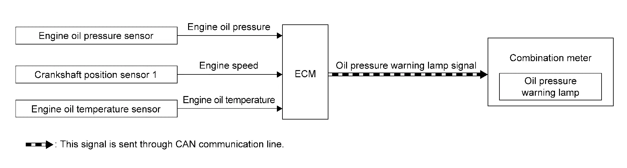
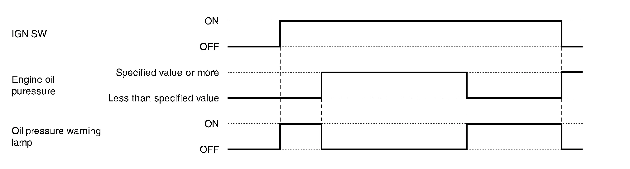
Warning Lamps/indicator Lamps
Engine Oil Pressure Warning Lamp
DESIGN/PURPOSE
When engine oil pressure is low, the oil pressure warning lamp informs the driver of low oil pressure to prevent damage to the engine.
BULB CHECK
Not applicable
OPERATION AT COMBINATION METER CAN COMMUNICATION CUT-OFF OR UNUSUAL SIGNAL
For the operation for CAN communications blackout or abnormal signal reception, refer to Fail-Safe.
SYSTEM DIAGRAM
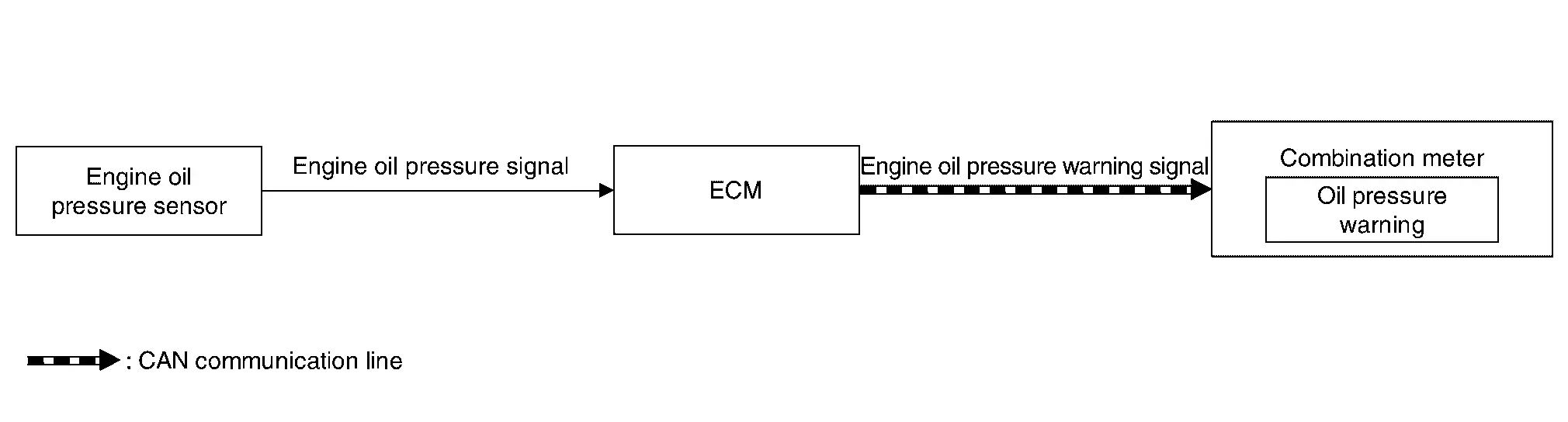
SIGNAL PATH
ECM calculates an engine oil pressure according to a signal transmitted from the engine oil pressure sensor. When the engine oil pressure is low, ECM transmits the engine oil pressure warning lamp signal to combination meter via CAN communication. Then the engine oil pressure warning lamp illuminates.
LIGHTING CONDITION
When any of the following conditions is satisfied:
-
Ignition switch: ON
-
Engine oil pressure is the specified value or more.
SHUTOFF CONDITION
When any of the following conditions is satisfied:
-
Ignition switch: OFF
-
Engine oil pressure is the specified value or more.
TIMING CHART
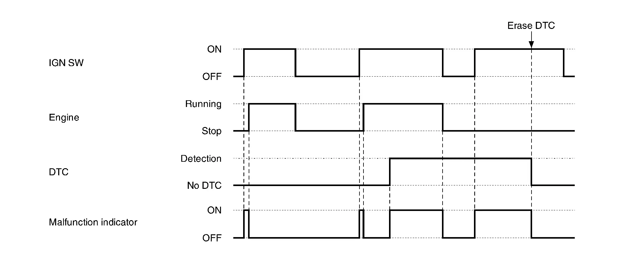
Malfunction Indicator Lamp (MIL)
DESIGN/PURPOSE
When a malfunction which increases exhaust gases is detected, ECM turns ON MIL and informs the driver of the necessity of inspection and repair.
When a malfunction which causes damage to the catalyst is detected, ECM immediately blinks MIL to alert the driver.
BULB CHECK
The bulb turns ON after turning ON the ignition switch (engine stop) and turns OFF after restarting the engine.
OPERATION AT COMBINATION METER CAN COMMUNICATION CUT-OFF OR UNUSUAL SIGNAL
For the operation for CAN communication blackout in the combination meter, refer to Fail-Safe.
SYSTEM DIAGRAM
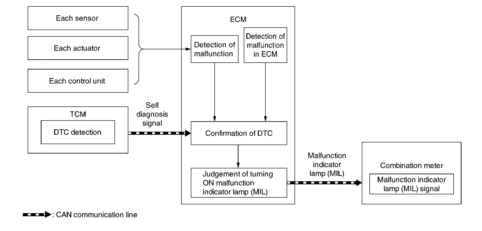
SIGNAL PATH
-
When the lighting conditions of the malfunction indicator lamp (MIL) are satisfied, ECM transmits a malfunction indicator lamp (MIL) signal to the combination meter via CAN communication.
-
The combination meter turns ON or blinks the malfunction indicator lamp (MIL), according to a signal received from ECM.
LIGHTING CONDITION
When all of the following conditions are satisfied:
-
Ignition switch: ON
-
DTC which influences on exhaust gasses is judged.
For DTCs that the malfunction indicator lamp turns ON and the number of DTC diagnosis trips, refer to DTC Index.
SHUTOFF CONDITION
When any of the following conditions is satisfied:
-
Ignition switch: OFF
-
Erase DTC
TIMING CHART
Infomation Display (combination Meter)
Indicator/Information
| Item | Symbol | Function |
|---|---|---|
| Auto engine shutoff system indicator |
|
|
| ASCD indicator |
|
For detail of ASCD function, refer to System Description. |
| Oil control system (OCS) indicator |
|
For detail of OCS function, refer to System Description. |
|
|
||
|
|
 NOTE:
NOTE:
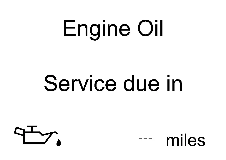
Engine warning
DESIGN/PURPOSE
Warn the driver that the state of the engine.
| Symbol | Message |
|---|---|
|
|
|

BULB CHECK
Not applicable
OPERATION AT COMBINATION METER CAN COMMUNICATION CUT-OFF OR UNUSUAL SIGNAL
For the operation for CAN communications blackout or abnormal signal reception, Fail-Safe (FULL TFT METER) or Fail-Safe (7 INCH INFORMATION DISPLAY).
SYSTEM DIAGRAM
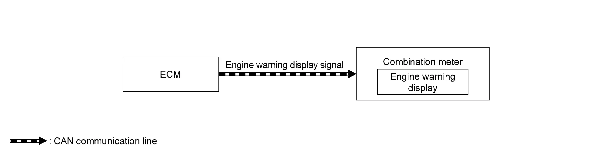
SIGNAL PATH
ECM transmits the engine warning display signal to combination meter via CAN communication.
Then the engine warning displays.
LIGHTING CONDITION
When all of the following conditions is satisfied:
-
Ignition switch: ON
-
Failure of powertrain which may cause serious accident is detected.
-
Driving condition may cause accident or situation that car cannot run.
SHUTOFF CONDITION
When any of the following conditions is satisfied:
-
Ignition switch: OFF
-
Failure of powertrain which may cause serious accident is not detected.
-
No problem about driving condition.
TIMING CHART
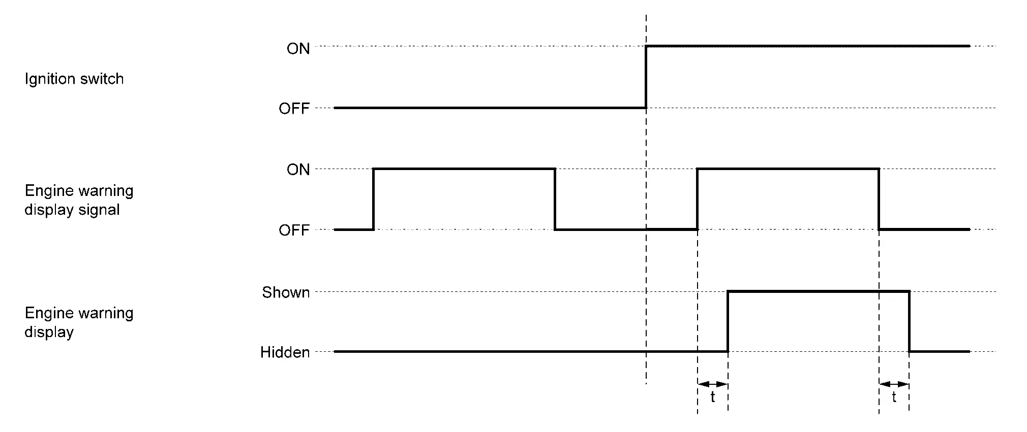
| t | : 100 ms |
Warning Chime
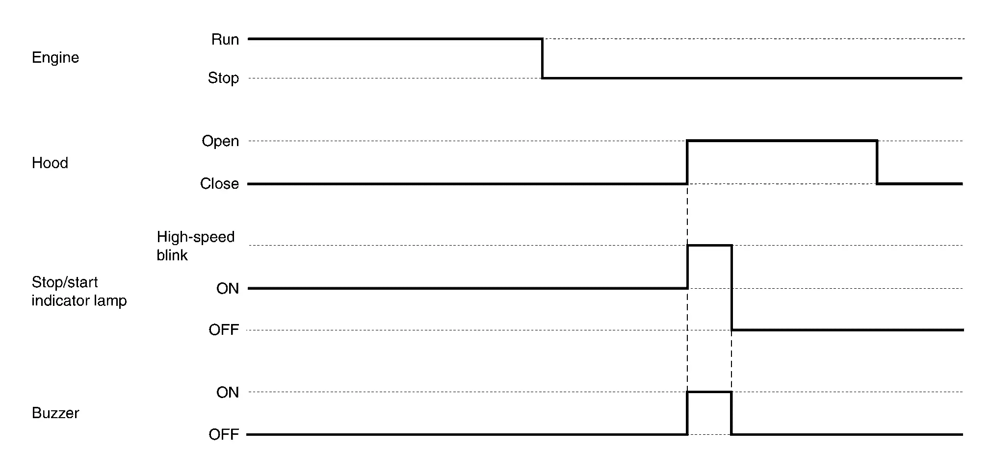
Stop/Start warning
PURPOSE
The combination meter alerts the driver by sounding the integrated buzzer and blinking the indicator lamp at high speed when the driver′s operation is judged as improper operation while the stop/start system is operating.
SYNCHRONIZATION WITH WARNING/INDICATOR (INFORMATION DISPLAY)
Applicable
For warning/indicator (information display), refer to Indicator/Information.
SYSTEM DIAGRAM
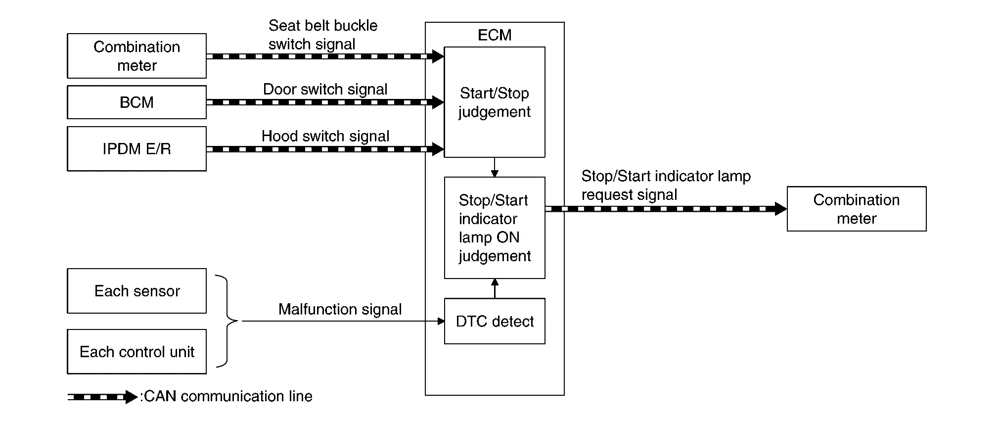
SIGNAL PATH
-
IPDM E/R transmits a hood switch signal to ECM via CAN communication.
-
BCM transmits a door switch signal to ECM via CAN communication.
-
The combination meter transmits a seat belt buckle switch signal to ECM via CAN communication.
-
ECM judges a stop/start system warning according to a received signal and transmits a stop/start indicator lamp request signal to the combination meter via CAN communication.
-
The combination meter sounds the warning buzzer and blinks the indicator lamp when receiving a stop/start indicator lamp request signal.
WARNING OPERATING CONDITION
When the following conditions are satisfied during stop/start system operation:
-
Hood is opened.
 NOTE:
NOTE:
The stop/start system is cancelled and the engine stops when the hood is opened.To restart the engine, use the key switch.
WARNING CANCEL CONDITION
-
Stop/start system is cancelled after the hood is opened.
-
Driver′s door is closed.
-
Driver′s seat belt is buckled.
TIMING CHART
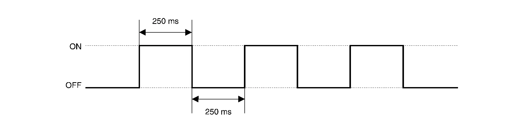
SOUND SPECIFICATION
Warning/indicator/chime List
Warning Lamp/Indicator Lamp
 NOTE:
NOTE:
Regarding the arrangement. Refer to Design (FULL TFT METER) or Design (7 INCH INFORMATION DISPLAY).
| Item | Design | Reference |
|---|---|---|
| Engine Oil Pressure Warning Lamp |
 |
Regarding the function. Refer to Engine Oil Pressure Warning Lamp. |
| Malfunction indicator lamp (MIL) |
 |
Regarding the function. Refer to Malfunction Indicator Lamp (MIL). |
Warning/Indicator (On Information Display)
| Item | Reference | |
|---|---|---|
| ASCD indicator | Refer to Indicator/Information. | |
| Engine warning | Refer to Engine warning. | |
| Oil control system (OCS) indicator | Refer to Indicator/Information. | |
| Stop/Start indicator | Refer to Switch Name and Function. | |
Warning Chime
| Item | Reference | |
|---|---|---|
| Stop/Start warning | Refer to Stop/Start warning. | |

Nissan Pathfinder (R53) 2022-2026 Service Manual
Contact Us
Nissan Pathfinder Info Center
Email: info@nipathfinder.com
Phone: +1 (800) 123-4567
Address: 123 Pathfinder Blvd, Nashville, TN 37214, USA
Working Hours: Mon–Fri, 9:00 AM – 5:00 PM (EST)
