Nissan Pathfinder: System Description - Component Parts ++
Engine Control System
Component Parts Location
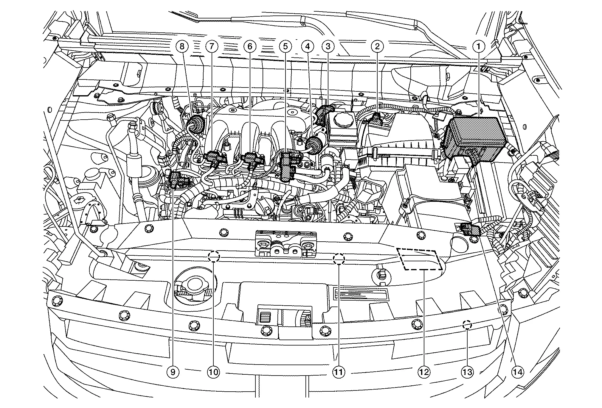
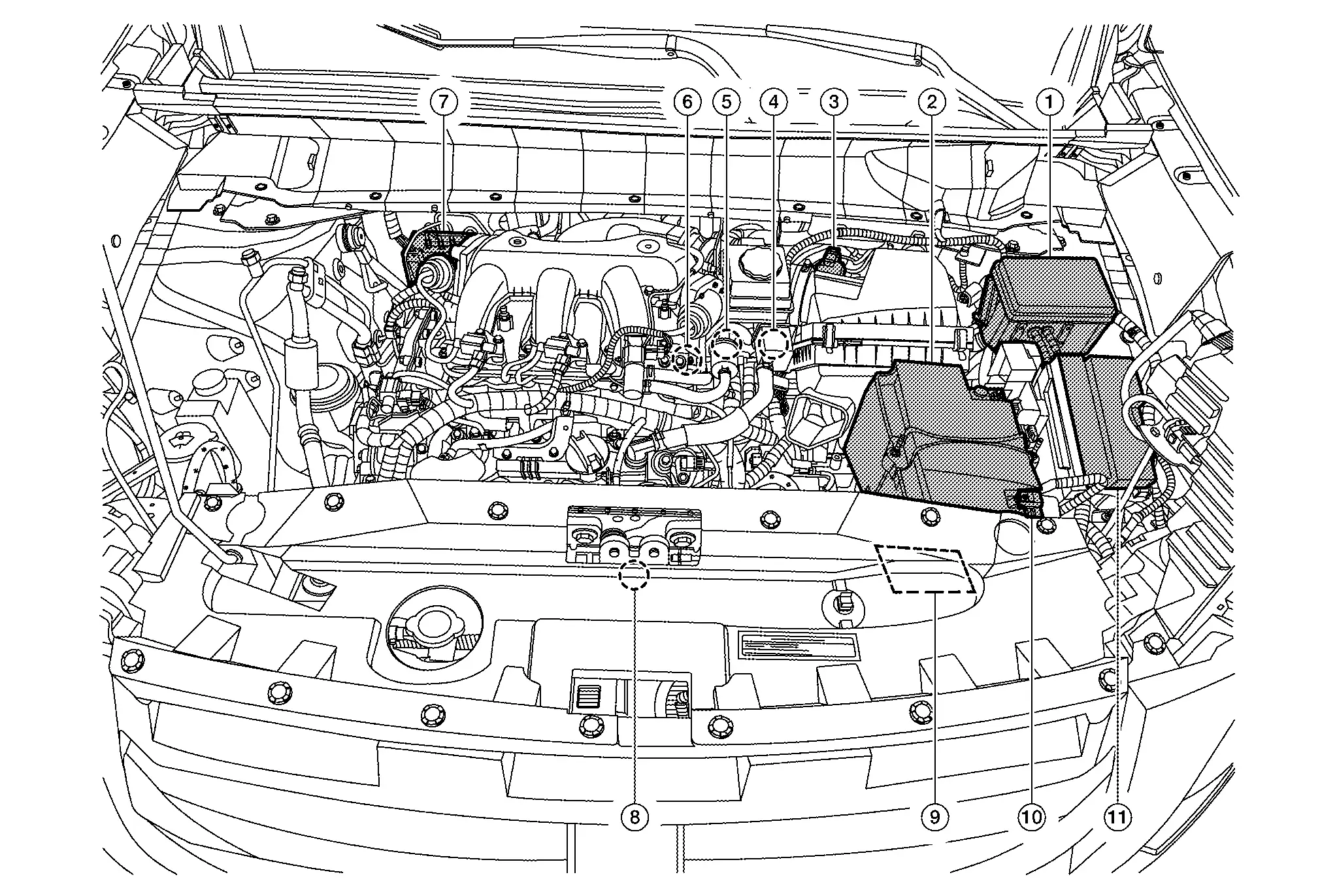
Engine Room Component
 |
IPDM E/R |
 |
Mass air flow sensor (with intake air temperature sensor) |
 |
Electric throttle control actuator |
 |
Power valve actuator 2 |
 |
EVAP canister purge volume control solenoid valve |
 |
VIAS control solenoid valve 2 |
 |
VIAS control solenoid valve 1 |
 |
Power valve actuator 1 |
 |
Electronic controlled engine mount control solenoid valve |
 |
Cooling fan motor-2 |
 |
Cooling fan motor-1 |
 |
ECM (with barometric pressure sensor) |
 |
Refrigerant pressure sensor |
 |
Battery current sensor |
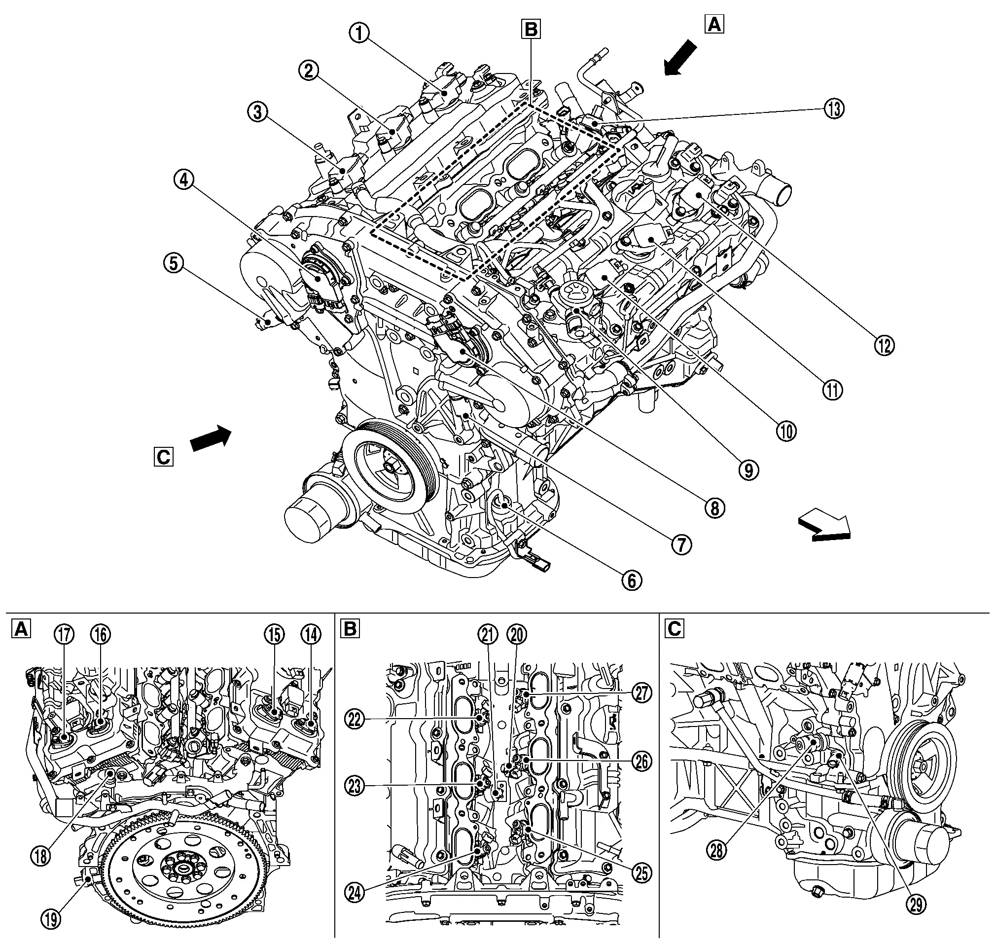
Engine Assembly Component
 |
Rear view of the engine |
 |
Top view of the engine |
 |
Side view of the engine |
 |
Nissan Pathfinder Vehicle front |
 |
Ignition coil (with power transistor) and spark plug (No.5 cylinder) |
 |
Ignition coil (with power transistor) and spark plug (No.3 cylinder) |
 |
Ignition coil (with power transistor) and spark plug (No.1 cylinder) |
 |
Electric intake valve timing control actuator (bank 1) |
 |
Exhaust valve timing control solenoid valve (bank 1) |
 |
Engine oil pressure control solenoid valve |
 |
Exhaust valve timing control solenoid valve (bank 2) |
 |
Electric intake valve timing control actuator (bank 2) |
 |
High pressure fuel pump |
 |
Ignition coil (with power transistor) and spark plug (No.2 cylinder) |
 |
Ignition coil (with power transistor) and spark plug (No.4 cylinder) |
 |
Ignition coil (with power transistor) and spark plug (No.6 cylinder) |
 |
Fuel rail pressure sensor |
 |
Exhaust camshaft position sensor (bank 1) |
 |
Intake camshaft position sensor (bank 1) |
 |
Intake camshaft position sensor (bank 2) |
 |
Exhaust camshaft position sensor (bank 2) |
 |
Engine coolant temperature sensor |
 |
Crankshaft position sensor 1 |
 |
Knock sensor (bank 2) |
 |
Knock sensor (bank 1) |
 |
Fuel injector (No.5 cylinder) |
 |
Fuel injector (No.3 cylinder) |
 |
Fuel injector (No.1 cylinder) |
 |
Fuel injector (No.2 cylinder) |
 |
Fuel injector (No.4 cylinder) |
 |
Fuel injector (No.6 cylinder) |
 |
Engine oil pressure sensor |
 |
Engine oil temperature sensor |
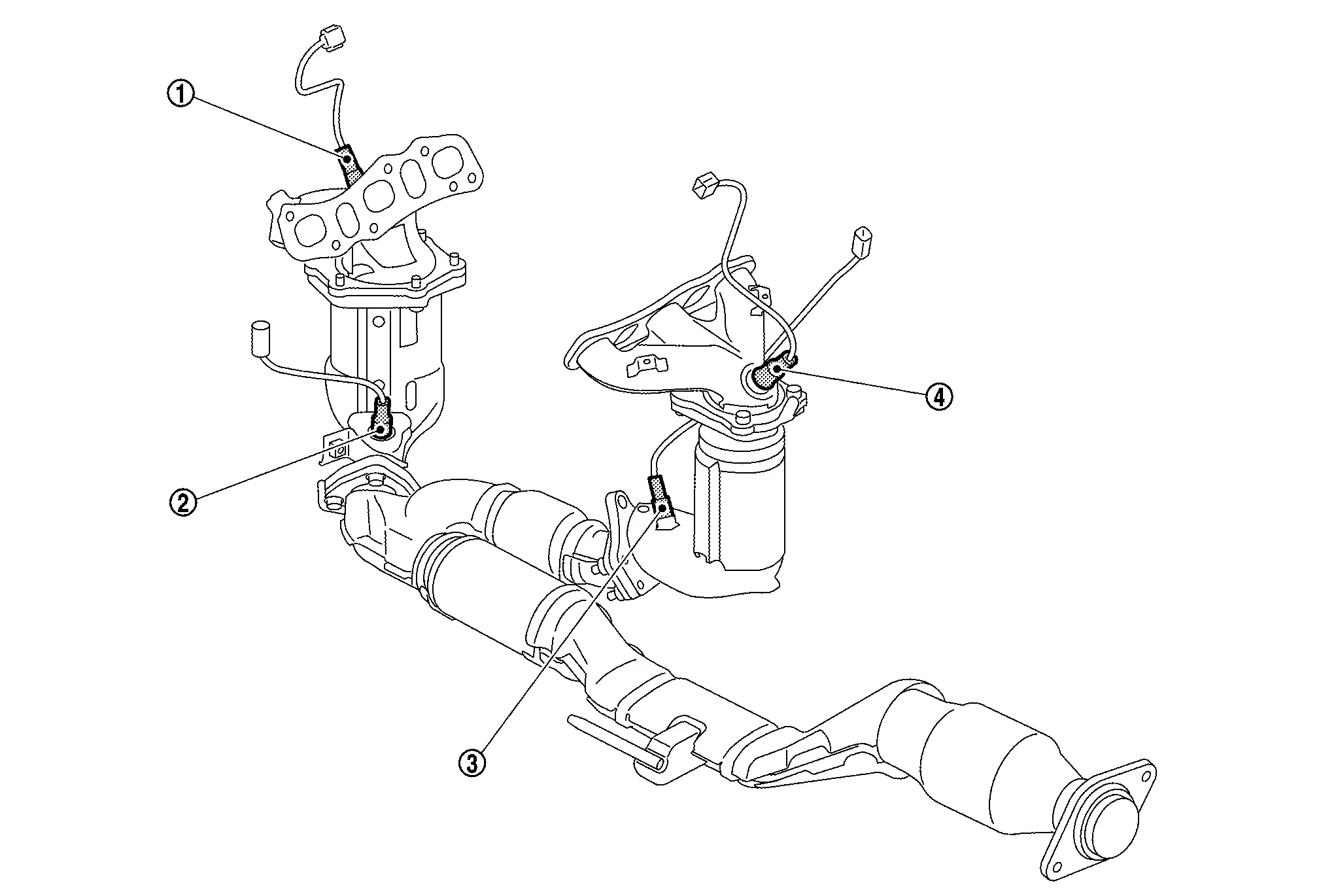
Exhaust System Component
 |
Air fuel ratio (A/F) sensor 1 (bank 2) |
 |
Heated oxygen sensor 2 (bank 2) |
 |
Heated oxygen sensor 2 (bank 1) |
 |
Air fuel ratio (A/F) sensor 1 (bank 1) |
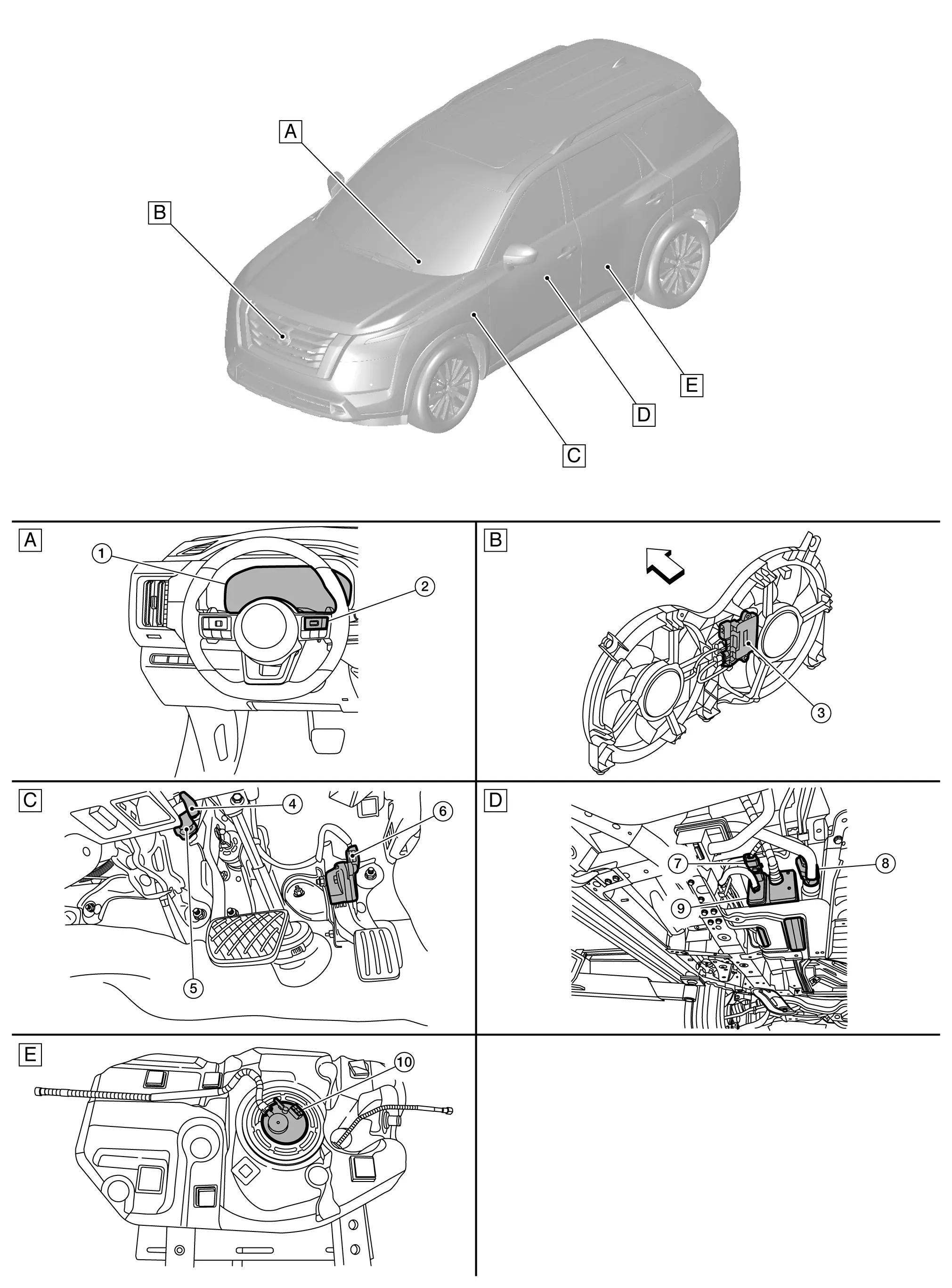
Vehicle Compartment
 |
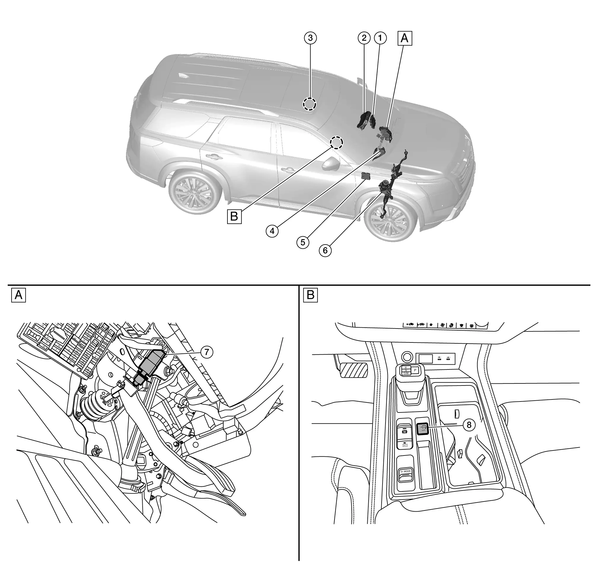
Instrument panel periphery |
 |
Front side of engine room |
 |
Pedal periphery |
 |
Undercarriage center area |
 |
Under of rear seat | ||
 |
Nissan Pathfinder Vehicle front |
 |
Combination meter |
 |
ASCD/ICC steering switch |
 |
Cooling fan control module |
 |
Brake pedal position switch |
 |
Stop lamp switch |
 |
Accelerator pedal position sensor |
 |
EVAP control system pressure sensor |
 |
EVAP canister vent control valve |
 |
EVAP canister |
 |
Fuel level sensor unit and fuel pump (with fuel tank temperature sensor) |
Stop/start System
Component Parts Location
Engine Room Component
 |
IPDM E/R |
 |
12 V Battery |
 |
Mass air flow sensor (with intake air temperature sensor) |
 |
Brake booster pressure sensor |
 |
Engine coolant temperature sensor |
 |
Crankshaft position sensor 2 |
 |
ABS actuator and electric unit (control unit) |
 |
Hood switch |
 |
ECM |
 |
Battery current sensor |
 |
Relay box |
Body Compartment
 |
Pedal periphery |
 |
Center console area |
 |
BCM |
 |
Combination meter |
 |
Door switch (driver side) |
 |
Accelerator pedal position sensor |
 |
A/C auto amp. |
 |
EPS control unit |
 |
Stop lamp switch |
 |
Stop/start OFF switch |
Accelerator Pedal Position Sensor
The accelerator pedal position sensor is integrated with the accelerator pedal. The sensor detects the accelerator position and sends a signal to the ECM.
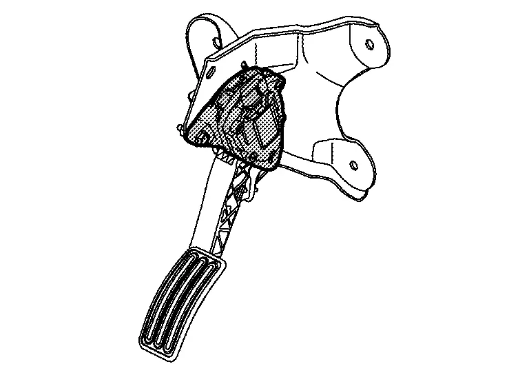
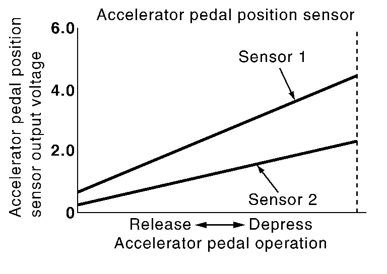
Accelerator pedal position sensor has 2 sensors. These sensors are a kind of potentiometer which transform the accelerator pedal position into output voltage, and emit the voltage signal to the ECM. The ECM judges the current opening angle of the accelerator pedal from these signals and controls the throttle control motor based on these signals.
Idle position of the accelerator pedal is determined by the ECM receiving the signal from the accelerator pedal position sensor. The ECM uses this signal for engine operations such as fuel cut.
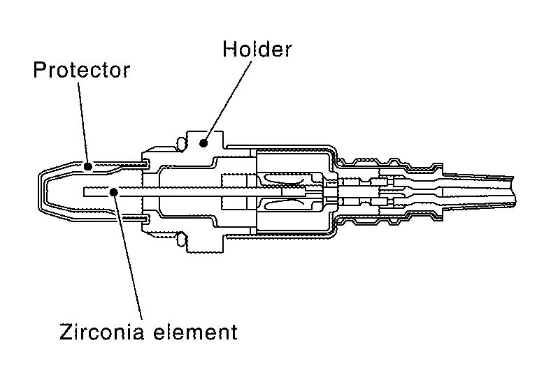
Air Fuel Ratio (A/F) Sensor 1
DESCRIPTION
The sensor element of the A/F sensor 1 is composed an electrode layer, which transports ions. It has a heater in the element.
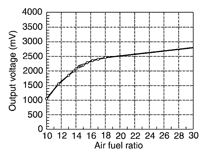
The sensor is capable of precise measurement
 = 1, but also in the lean and rich range. Together with its control electronics, the sensor outputs a clear, continuous signal throughout a wide
 range.
The exhaust gas components diffuse through the diffusion layer at the sensor cell. An electrode layer is applied voltage, and this current relative oxygen density in lean. Also this current relative hydrocarbon density in rich.
Therefore, the A/F sensor 1 is able to indicate air fuel ratio by this electrode layer of current. In addition, a heater is integrated in the sensor to ensure the required operating temperature of approximately 760°C (1,400°F).
A/F SENSOR 1 HEATER
A/F sensor 1 heater is integrated in the sensor.
The ECM performs ON/OFF duty control of the A/F sensor 1 heater corresponding to the engine operating condition to keep the temperature of A/F sensor 1 element within the specified range.
ASCD Steering Switch
ASCD steering switch has variant values of electrical resistance for each button. ECM reads voltage variation of switch, and determines which button is operated.
Refer to System Description for the ASCD function.
Cooling Fan
COOLING FAN CONTROL MODULE
Cooling fan control module receives ON/OFF pulse duty signal from IPDM E/R. Corresponding to this ON/OFF pulse duty signal, cooling fan control module sends cooling fan motor operating voltage to cooling fan motor. The revolution speed of cooling fan motor is controlled by duty cycle of the voltage.
COOLING FAN MOTOR
Cooling fan motor receives cooling fan motor operating voltage from cooling fan control module. The revolution speed of cooling fan motor is controlled by duty cycle of the voltage.
COOLING FAN RELAY
Cooling fan relay provides power supply to the cooling fan control module.
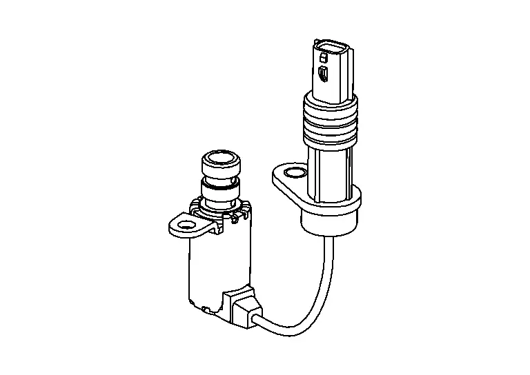
Crankshaft Position Sensor 1
The crankshaft position sensor 1 is located on the transmission housing facing the gear teeth (cogs) of the signal plate. It detects the fluctuation of the engine revolution.
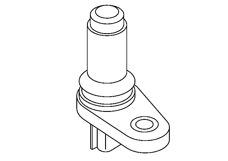
The sensor consists of a permanent magnet and Hall IC.
When the engine is running, the high and low parts of the teeth cause the gap with the sensor to change.
The changing gap causes the magnetic field near the sensor to change.
Due to the changing magnetic field, the voltage from the sensor changes.
The ECM receives the voltage signal and detects the fluctuation of the engine revolution.
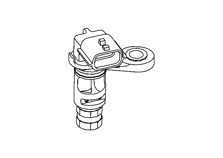
Crankshaft Position Sensor 2
FUNCTIONS WITHIN THE SYSTEM
The ECM judges the piston position of each cylinder based on the crankshaft position sensor 2 signal that is input into it.
INDIVIDUAL FUNCTION WITHIN THE SYSTEM
The ECM inputs the voltage change caused by the change in magnetic field generated close to the crankshaft position sensor 2 as signal voltage.
INDIVIDUAL OPERATION
Crankshaft position sensor 2 consists of a permanent magnet and Hall IC. When the engine is running, the gap between ring gear and crankshaft position sensor 2 is changed by the gear teeth. The changing gap causes the magnetic field near the sensor to change. Due to the changing magnetic field, the voltage from the sensor changes. Detailed piston position can be detected by reading this because the ring gear includes more teeth than the signal plate detected by crank shaft position sensor 1.
COMPONENT PARTS LOCATION
Crankshaft position sensor 2 is installed on upper the converter housing.
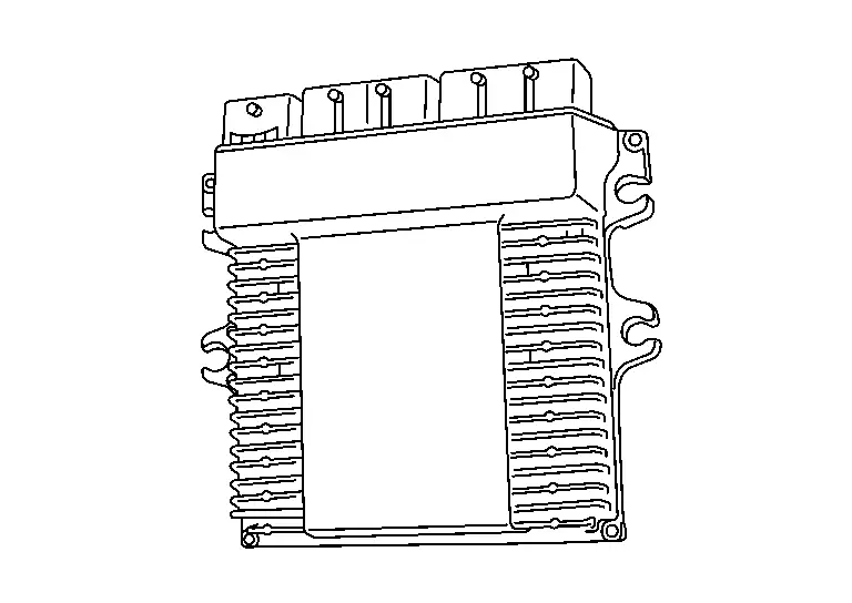
ECM (With Barometric Pressure Sensor)
The ECM consists of a microcomputer and connectors for signal input and output and for power supply. The ECM controls the engine.
Electric Intake Valve Timing Control Actuator
The electric intake valve timing (IVT) control actuator activates the actuator motor according to a signal from the electric IVT control module to maintain the timing of intake valve timing at advance angle or retard angle.
The actuator has position sensor and transmits a motor position signal and a motor speed signal to Electric IVT Control Module.
 NOTE:
NOTE:
The actuator is non separable.
Electric Intake Valve Timing Control Module
The electric intake valve timing (IVT) control module controls the electric IVT control actuator, according to signals sent from ECM and the sensor built in the electric IVT control actuator.
The target angle of valve timing is adjusted based on the engine communication signals transmitted from ECM.
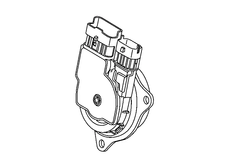
Electric Throttle Control Actuator
THROTTLE CONTROL MOTOR
The throttle control motor is operated by the ECM and it opens and closes the throttle valve.
The current opening angle of the throttle valve is detected by the throttle position sensor and it provides feedback to the ECM to control the throttle control motor to make the throttle valve opening angle properly in response to driving condition.
THROTTLE POSITION SENSOR
Electric throttle control actuator consists of throttle control motor, throttle position sensor, etc. The throttle position sensor responds to the throttle valve movement.
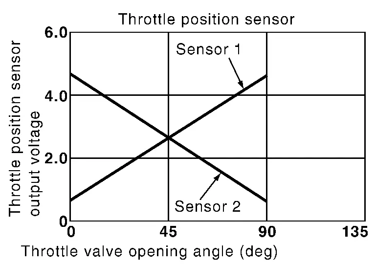
The throttle position sensor has two sensors. These sensors are a kind of potentiometer which transform the throttle valve position into output voltage, and emit the voltage signals to the ECM. The ECM judges the current opening angle of the throttle valve from these signals and controls the throttle valve opening angle properly in response to driving condition via the throttle control motor.
Electronic Controlled Engine Mount
In the idle range, ECM turns OFF the electronically-controlled engine mount control solenoid valve and applies manifold pressure to the electronically-controlled engine mount. This decreases damping force of the electronically-controlled engine mount and absorbs vibrations traveling from the engine to the body for improving the quietness.
In the driving range, ECM turns ON the electronically-controlled engine mount control solenoid valve and cuts manifold pressure applied on the electronically-controlled engine mount. This increases damping force of the electronically-controlled engine mount and reduces vibrations generated during driving.
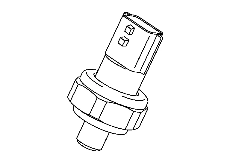
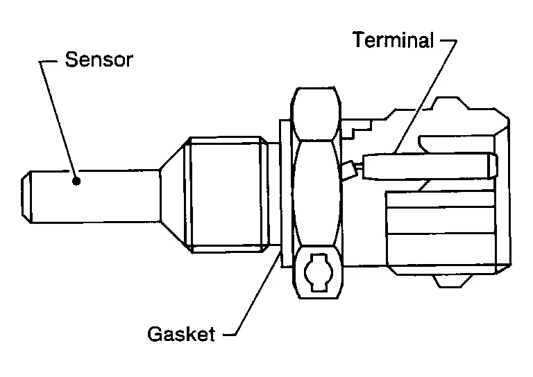
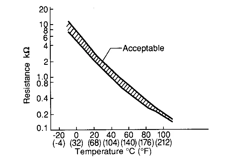
Engine Coolant Temperature Sensor
The engine coolant temperature sensor is used to detect the engine coolant temperature. The sensor modifies a voltage signal from the ECM. The modified signal returns to the ECM as the engine coolant temperature input. The sensor uses a thermistor which is sensitive to the change in temperature. The electrical resistance of the thermistor decreases as temperature increases.

<Reference data>

| Engine coolant temperature [°C (°F)] | Voltage* (V) | Resistance (kΩ) |
|---|---|---|
| −10 (14) | 4.4 | 7.0 – 11.4 |
| 20 (68) | 3.5 | 2.10 – 2.90 |
| 50 (122) | 2.2 | 0.68 – 1.00 |
| 90 (194) | 0.9 | 0.236 – 0.260 |
*: These data are reference values and are measured between ECM terminals and sensor ground.
Engine Oil Pressure Control Solenoid Valve
The engine oil pressure control solenoid valve performs the variable hydraulic control (low oil pressure control and high oil pressure control) according to oil temperature and engine load.
Engine Oil Pressure Sensor
The engine oil pressure (EOP) sensor is detects engine oil pressure and transmits a voltage signal to the ECM.
Engine Oil Temperature Sensor
The engine oil temperature sensor is used to detect the engine oil temperature. The sensor modifies a voltage signal from the ECM. The modified signal returns to the ECM as the engine oil temperature input. The sensor uses a thermistor which is sensitive to the change in temperature. The electrical resistance of the thermistor decreases as temperature increases.
<Reference data>
| Engine oil temperature [°C (°F)] | Voltage* (V) | Resistance (kΩ) |
|---|---|---|
| −10 (14) | 4.4 | 7.0 – 11.4 |
| 20 (68) | 3.5 | 2.10 – 2.90 |
| 50 (122) | 2.2 | 0.68 – 1.00 |
| 90 (194) | 0.9 | 0.236 – 0.260 |
| 110 (230) | 0.6 | 0.143 – 0.153 |
*: These data are reference values and are measured between ECM terminals and sensor ground.
EVAP Canister Purge Volume Control Solenoid Valve
The EVAP canister purge volume control solenoid valve is used to control the flow rate of fuel vapor from the EVAP canister. The EVAP canister purge volume control solenoid valve is moved by ON/OFF pulses from the ECM. The longer the ON pulse, the greater the amount of fuel vapor that will flow through the valve.
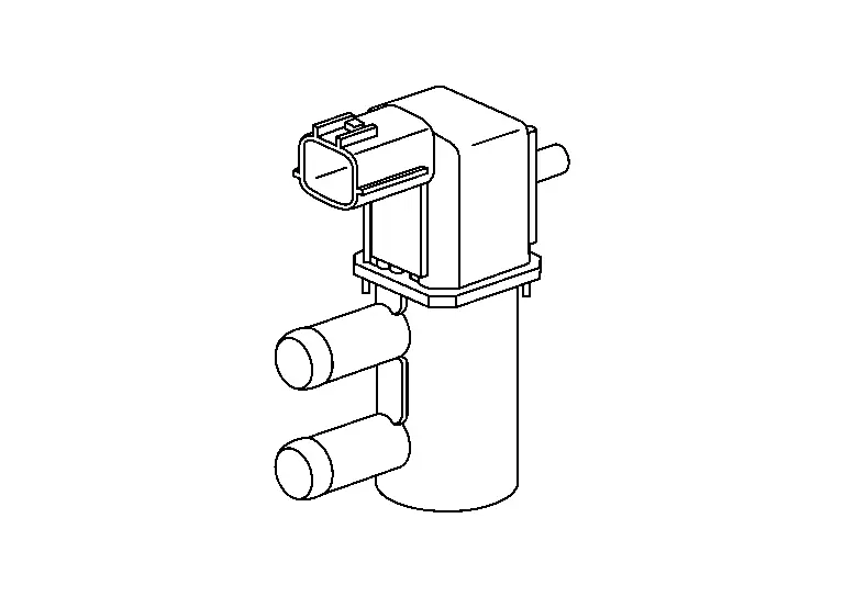
EVAP Canister Vent Control Valve
The EVAP canister vent control valve is located on the EVAP canister and is used to seal the canister vent.
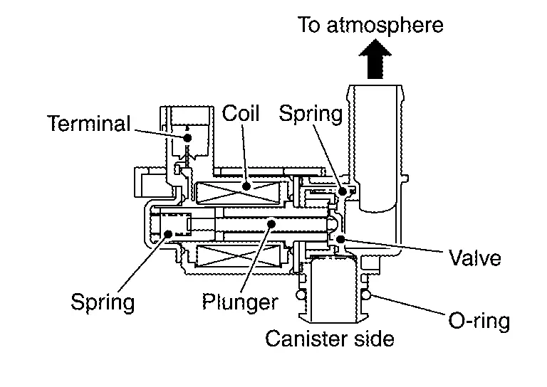
This solenoid valve responds to signals from the ECM. When the ECM sends an ON signal, the coil in the solenoid valve is energized. A plunger will then move to seal the canister vent. The ability to seal the vent is necessary for the on board diagnosis of other evaporative emission control system components.
This solenoid valve is used only for diagnosis, and usually remains opened.
When the vent is closed, under normal purge conditions, the evaporative emission control system is depressurized and allows “EVAP Control System” diagnosis.
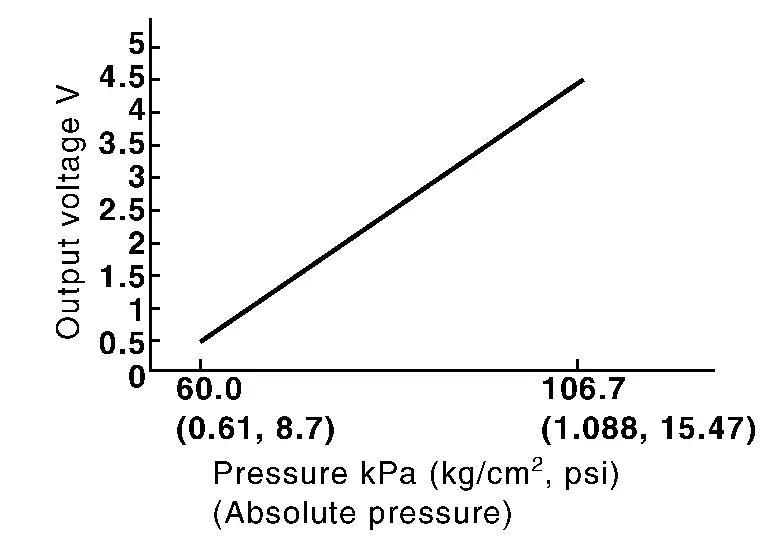
EVAP Control System Pressure Sensor
The EVAP control system pressure sensor detects pressure in the purge line. The sensor output voltage to the ECM increases as pressure increases.
Exhaust Camshaft Position Sensor
The exhaust camshaft position sensor senses the retraction of camshaft to identify a particular cylinder. The sensor senses piston position of the each cylinder for precise combustion.

When the crankshaft position sensor system becomes inoperative, the camshaft position sensor provides various controls of engine parts instead, utilizing timing of cylinder identification signals.
The cylinder identification is performed by the crankshaft position sensor and the camshaft position sensors (Bank 1 and Bank 2). For this reason, if one of the camshaft position sensors has a malfunction, the other camshaft position sensor can work with the crankshaft position sensor.
The sensor consists of a permanent magnet and Hall IC.
When engine is running, the high and low parts of the teeth cause the gap with the sensor to change.
The changing gap causes the magnetic field near the sensor to change.
Due to the changing magnetic field, the voltage from the sensor changes.
Exhaust Valve Timing Control Solenoid Valve
Exhaust valve timing control solenoid valve is activated by ON/OFF pulse duty (ratio) signals from the ECM.
The exhaust valve timing control solenoid valve changes the oil amount and direction of flow through exhaust valve timing control unit or stops oil flow.
The longer pulse width retards valve angle.
The shorter pulse width advances valve angle.
When ON and OFF pulse widths become equal, the solenoid valve stops oil pressure flow to fix the exhaust valve angle at the control position.
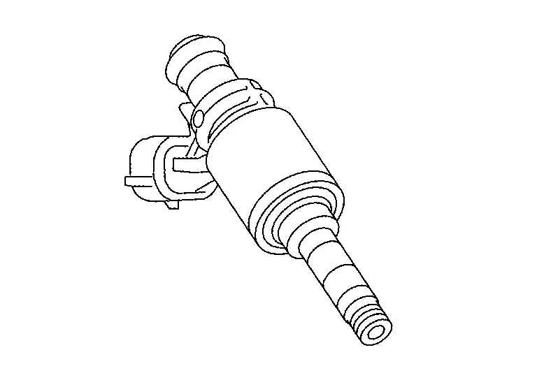
Fuel Injector
For the fuel injector, a high pressure fuel injector is used and this enables a high-pressure fuel injection at a high voltage within a short time. The ECM is equipped with an injector driver unit and actuates the fuel injector at a high voltage (approximately 65 V at the maximum).
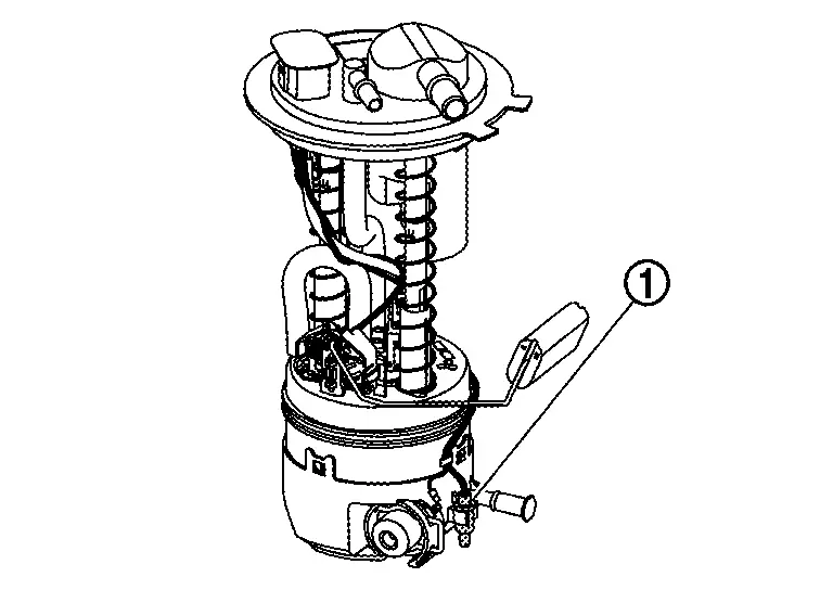
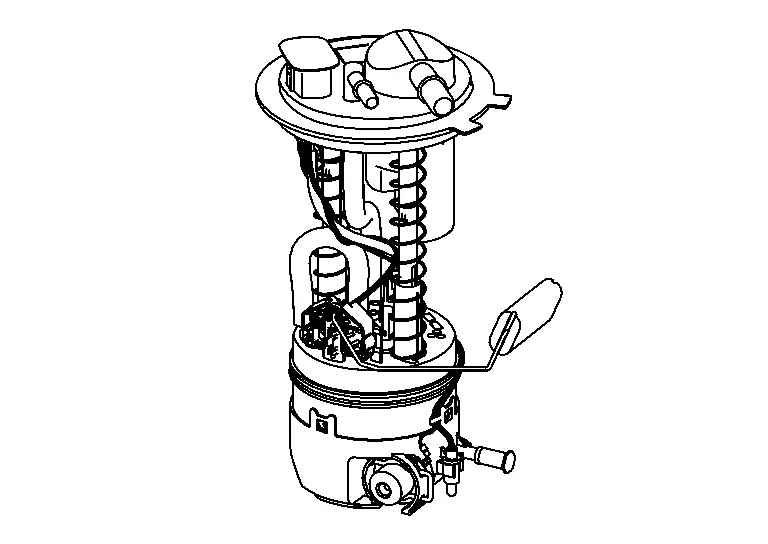
Fuel Level Sensor
The fuel level sensor
 is mounted in the fuel level sensor unit.
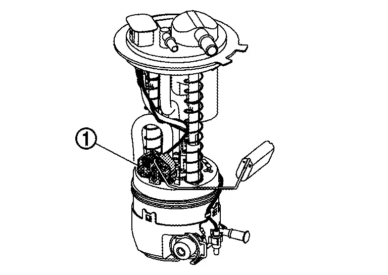
The sensor detects a fuel level in the fuel tank and transmits a signal to the combination meter. The combination meter sends the fuel level sensor signal to the ECM via the CAN communication line.
It consists of two parts, one is mechanical float and the other is variable resistor. Fuel level sensor output voltage changes depending on the movement of the fuel mechanical float.
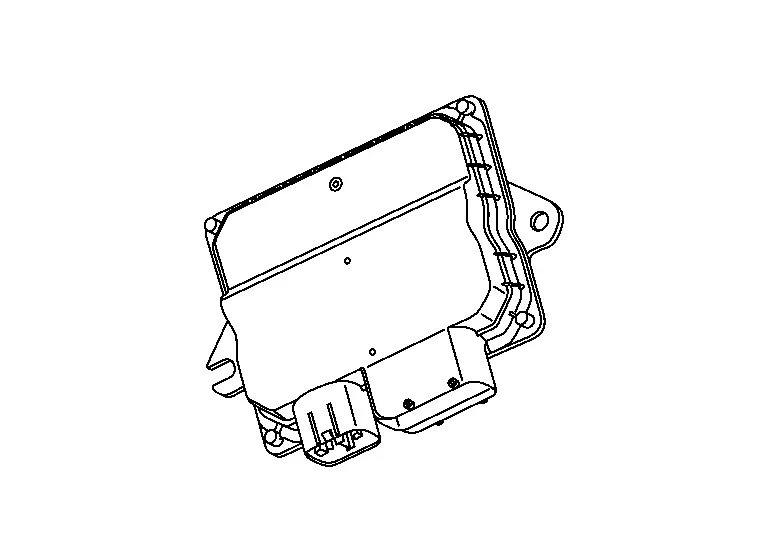
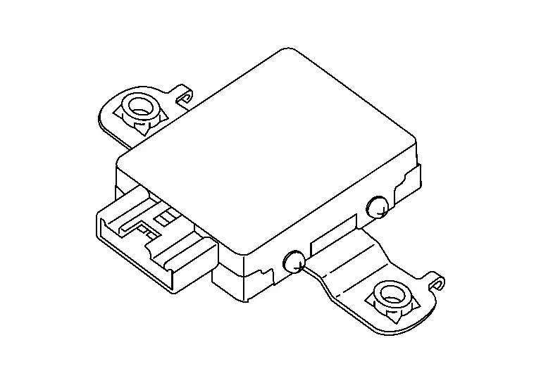
Fuel Pump Control Module
The fuel pump control module (FPCM) controls the fuel pump to satisfy a discharge rate suitable to a driving condition, according to the control from ECM. This reduces the electricity consumption of fuel pump during low load.
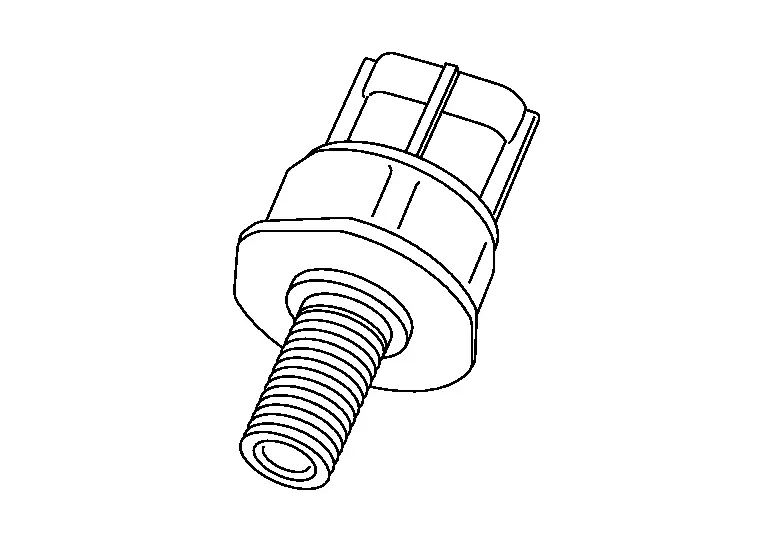
Fuel Rail Pressure Sensor
The fuel rail pressure (FRP) sensor is placed to the fuel rail and measures fuel pressure in the fuel rail. The sensor transmits voltage signal to the ECM. As the pressure increases, the voltage rises. The ECM controls the fuel pressure in the fuel rail by operating high pressure fuel pump. The ECM uses the signal from fuel rail pressure sensor as a feedback signal.
Fuel Tank Temperature Sensor
The fuel tank temperature sensor
 is used to detect the fuel temperature inside the fuel tank. The sensor modifies a voltage signal from the ECM. The modified signal returns to the ECM as the fuel temperature input. The sensor uses a thermistor which is sensitive to the change in temperature. The electrical resistance of the thermistor decreases as temperature increases.
<Reference data>

| Fluid temperature [°C (°F)] | Voltage* (V) | Resistance (kΩ) |
|---|---|---|
| 20 (68) | 3.5 | 2.3 – 2.7 |
| 50 (122) | 2.2 | 0.79 – 0.90 |
*: These data are reference values and are measured between ECM terminals and ECM ground.
Heated Oxygen Sensor 2
DESCRIPTION
The heated oxygen sensor 2, after three way catalyst 1, monitors the oxygen level in the exhaust gas on each bank.
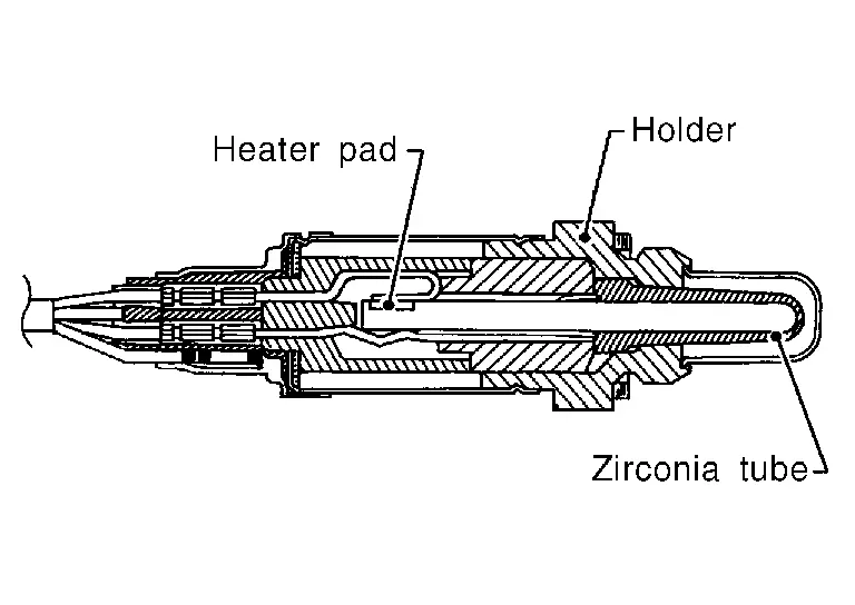
This sensor is made of ceramic zirconia. The zirconia generates voltage from approximately 1 V in richer conditions to 0 V in leaner conditions.
If a malfunction occurs in air fuel ratio (A/F) sensor, air fuel ratio is controlled to become a theoretical air fuel ratio by heated oxygen sensor 2.
Under normal conditions the heated oxygen sensor 2 is not used for engine control operation.
HEATED OXYGEN SENSOR 2 HEATER
Heated oxygen sensor 2 heater is integrated in the sensor.
The ECM performs ON/OFF control of the heated oxygen sensor 2 heater corresponding to the engine speed, amount of intake air and engine coolant temperature.
| Condition | Heated oxygen sensor 2 heater |
|---|---|
| Above 7,500 rpm | OFF |
|
Below 7,500 rpm after the following conditions are met.
|
ON |
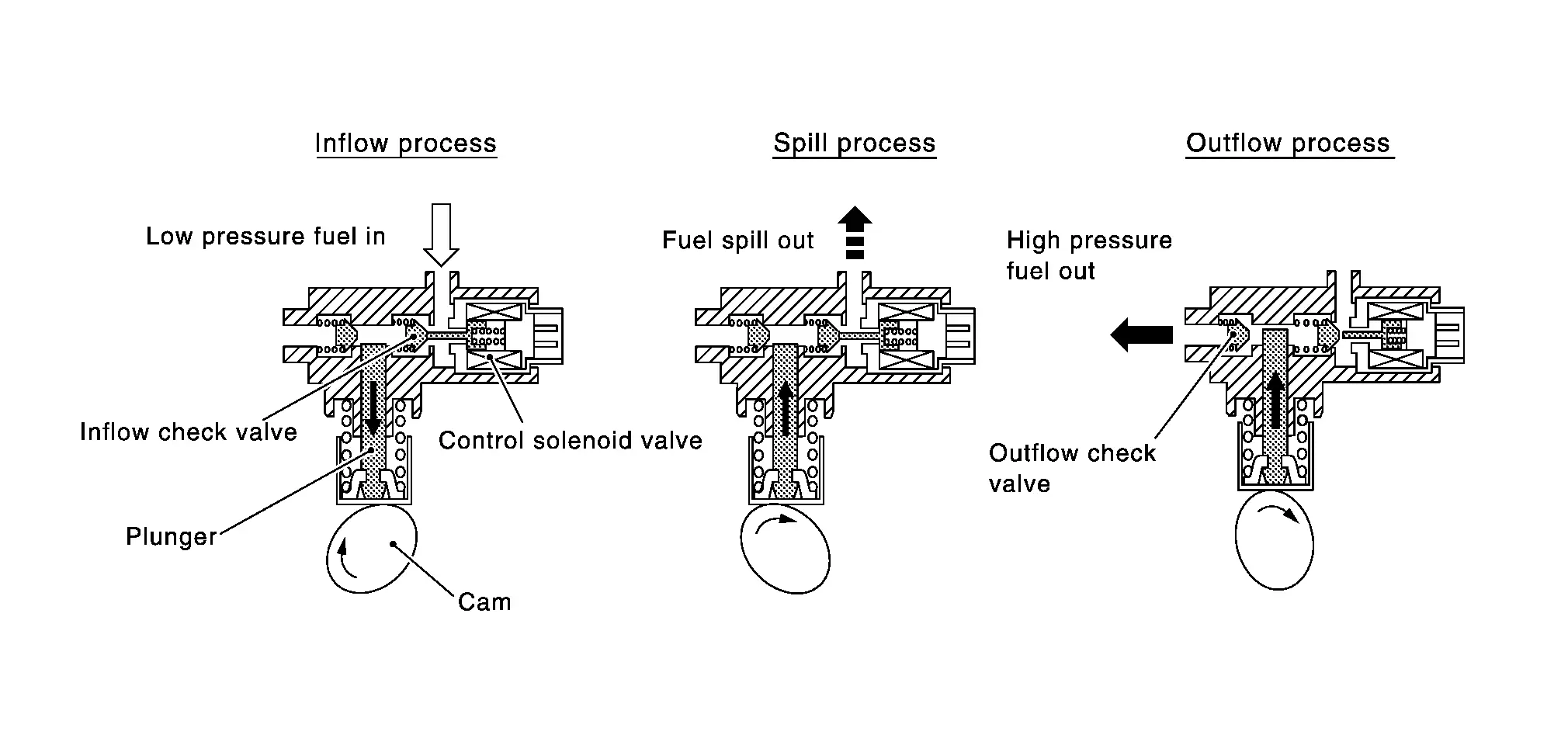
High Pressure Fuel Pump
The high pressure fuel pump is activated by the exhaust camshaft.
ECM controls the high pressure fuel pump control solenoid valve built into the high pressure fuel pump and adjusts the amount of discharge by changing the suction timing of the low pressure fuel.
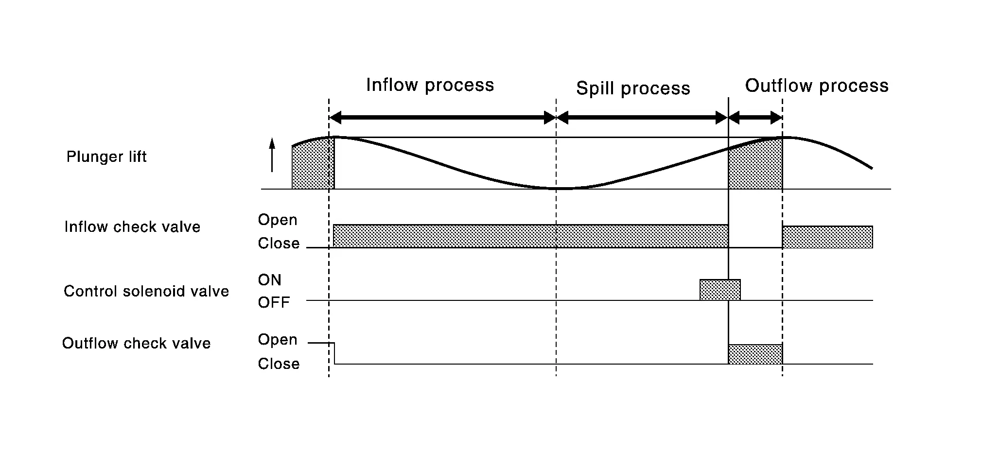
Operating Description
Operating Chart
Hood Switch
FUNCTIONS WITHIN THE SYSTEM
When the ECM receives the hood switch signal via CAN communication, it cancels the stop/start system.
INDIVIDUAL FUNCTION WITHIN THE SYSTEM
The hood switch detects the hood open/close status and inputs the hood switch signal into the IPDM E/R.
INDIVIDUAL OPERATION
The hood switch turns ON/OFF according to the hood status.
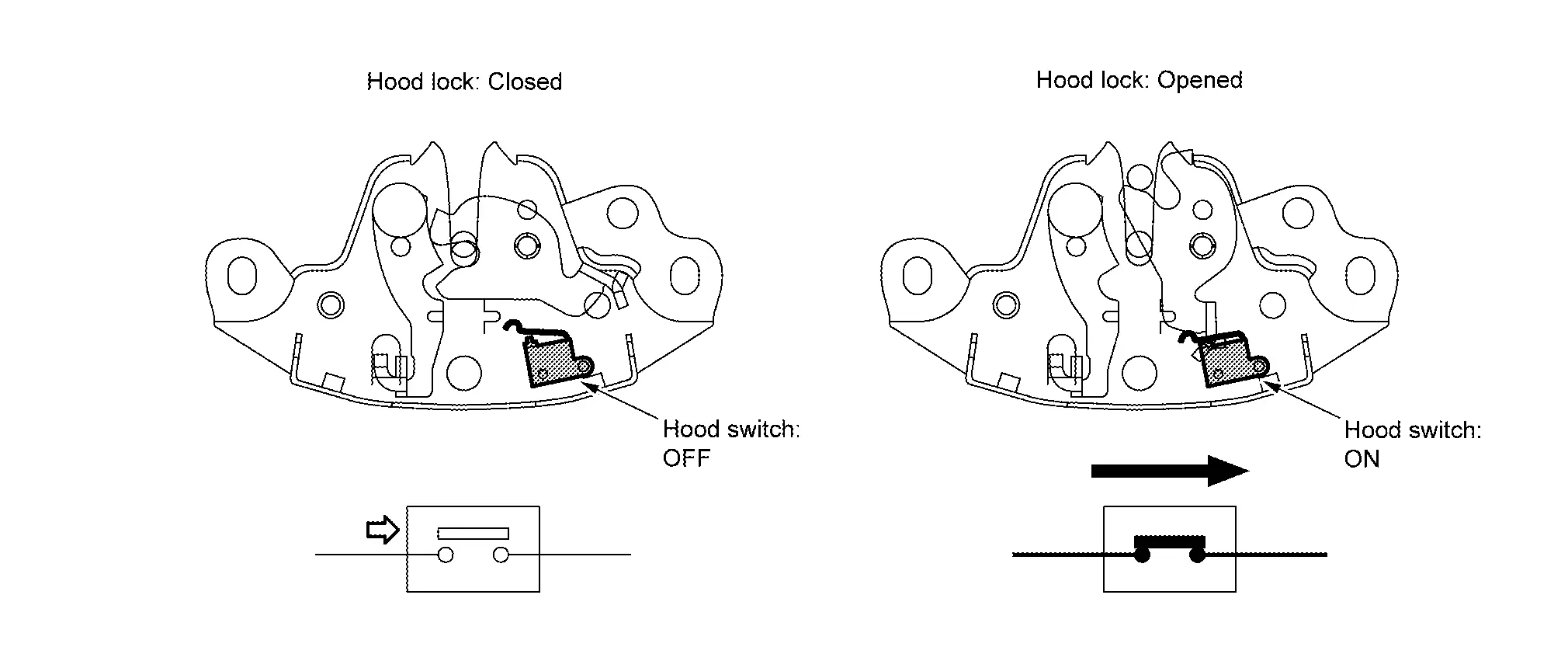
COMPONENT PARTS LOCATION
The hood switch is installed to the hood lock.
ICC Steering Switch
ICC steering switch has variant values of electrical resistance for each button. ECM reads voltage variation of switch, and determines which button is operated.
Refer to System Description for the ICC function.
Ignition Coil and Spark Plug
IGNITION COIL
The ignition signal from the ECM is sent to and amplified by the power transistor. The power transistor turns ON and OFF the ignition coil primary circuit. This ON/OFF operation induces the proper high voltage in the coil secondary circuit.
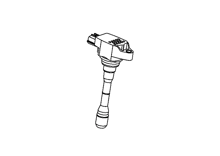
SPARK PLUG
The spark plug is installed to the cylinder head and performs ignitions to air-fuel mixture by discharging ignition coil-applied voltage in the gap between the center electrode and the ground electrode and generating sparks in the combustion chamber.
Intake Camshaft Position Sensor
Intake camshaft position sensor detects the protrusion of the signal plate installed to the intake camshaft rear end.
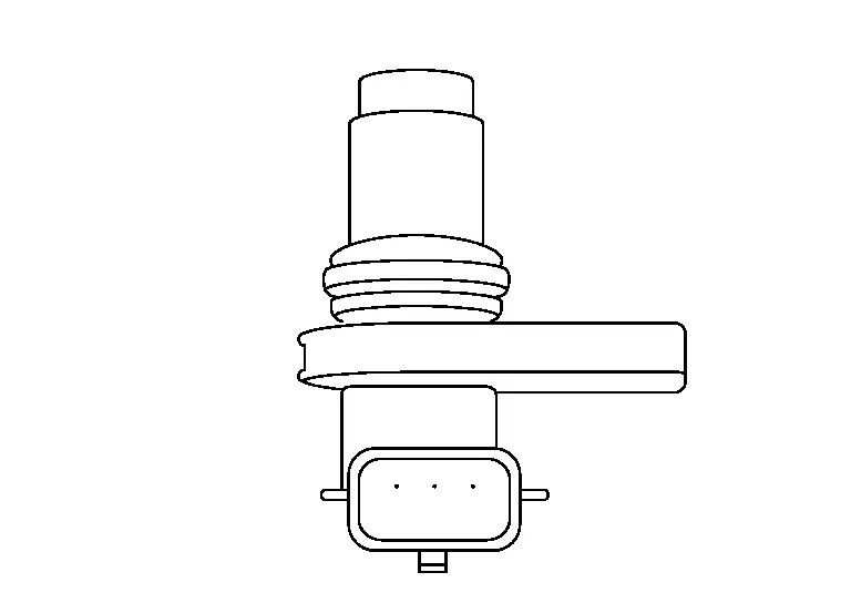
This sensor signal is used for sensing a position of the intake camshaft.
The sensor consists of a permanent magnet and Hall IC.
When engine is running, the high and low parts of the teeth cause the gap with the sensor to change.
The changing gap causes the magnetic field near the sensor to change.
Due to the changing magnetic field, the voltage from the sensor changes.
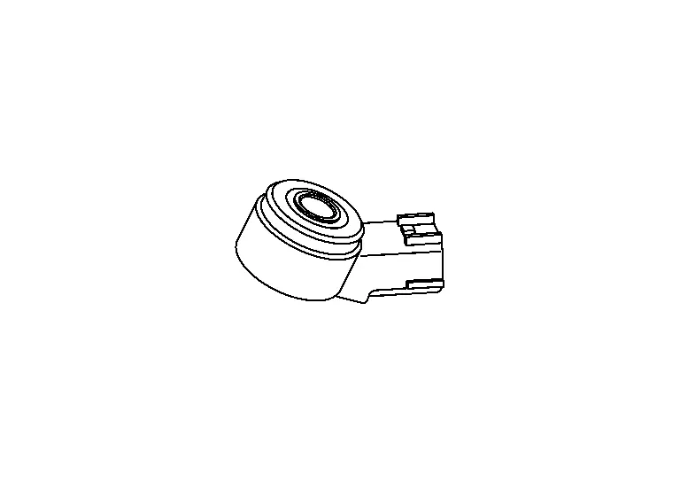
Knock Sensor
The knock sensor is attached to the cylinder block. It senses engine knocking using a piezoelectric element. A knocking vibration from the cylinder block is sensed as vibrational pressure. This pressure is converted into a voltage signal and sent to the ECM.
Low Pressure Fuel Pump
| Sensor | Input signal to ECM | ECM Function | Actuator |
|---|---|---|---|
|
Crankshaft position sensor 1 Exhaust camshaft position sensor |
Engine speed* | Fuel pump control |
Fuel pump relay ↓ Fuel pump |
| Battery | Battery voltage* |
*: ECM determines the start signal status by the signals of engine speed and battery voltage.
The ECM activates the fuel pump for several seconds after the ignition switch is turned ON to improve engine startability. If the ECM receives a engine speed signal from the camshaft position sensor, it knows that the engine is rotating, and causes the pump to operate. If the engine speed signal is not received when the ignition switch is ON, the engine stalls. The ECM stops pump operation and prevents battery discharging, thereby improving safety. The ECM does not directly drive the fuel pump. It controls the ON/OFF fuel pump relay, which in turn controls the fuel pump.
| Condition | Fuel pump operation |
|---|---|
| Ignition switch is turned to ON. | Operates for 1 second. |
| Engine running and cranking | Operates. |
| When engine is stopped | Stops in 1.5 seconds. |
| Except as shown above | Stops. |
Malfunction Indicator Lamp (MIL)
Malfunction Indicator lamp (MIL) is located on the combination meter.
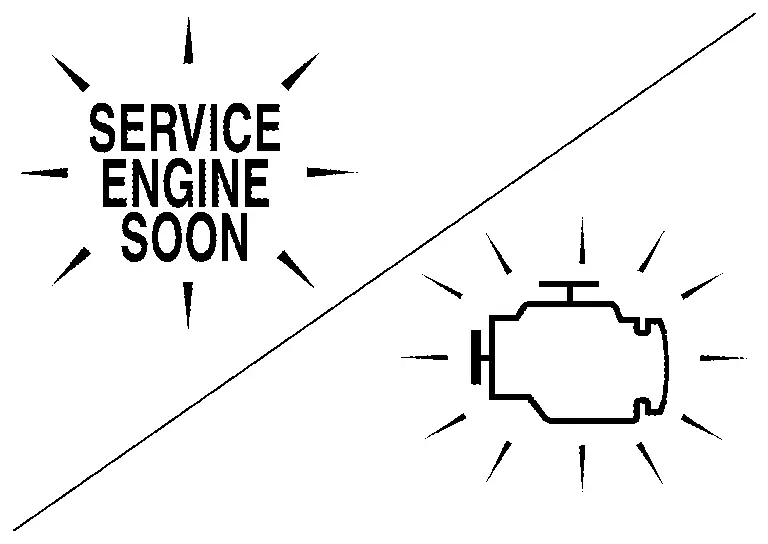
MIL will illuminate when the ignition switch is turned ON without the engine running. This is a bulb check.
When the engine is started, MIL should turn OFF. If the MIL remains illuminated, the on board diagnostic system has detected an engine system malfunction.
For details, refer to Malfunction Indicator Lamp (MIL).
Mass Air Flow Sensor (With Intake Air Temperature Sensor)
MASS AIR FLOW SENSOR
The mass air flow sensor
 is placed in the stream of intake air. It measures the intake flow rate by measuring a part of the entire intake flow. The MAF sensor controls the temperature of the heater in sensing element to a certain amount. The temperature distribution around the heater changes according to the increase in intake air volume. The change is detected by a thermistor and the air volume data is sent to ECM by the MAF sensor.
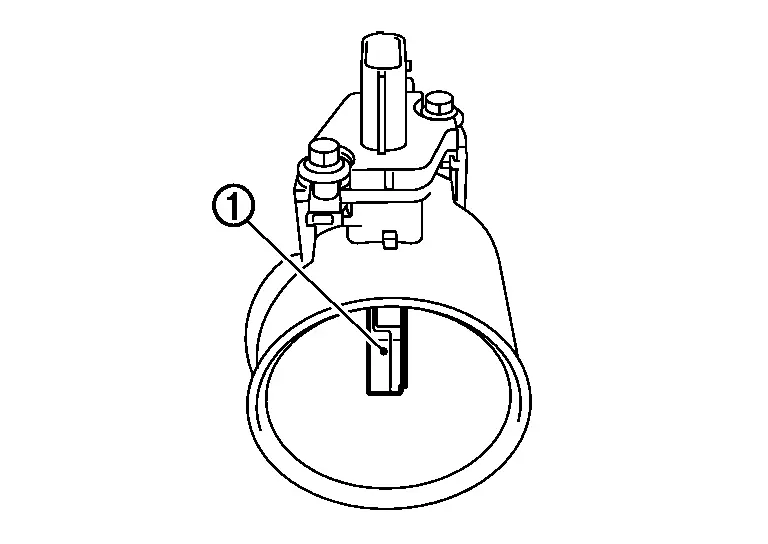
INTAKE AIR TEMPERATURE SENSOR
The intake air temperature sensor is built-into mass air flow sensor. The sensor detects intake air temperature and transmits a signal to the ECM.
The temperature sensing unit uses a thermistor which is sensitive to the change in temperature.
<Reference data>
|
Intake air temperature [°C (°F)] | Voltage* (V) |
|---|---|
| 25 (77) | 2.0 – 2.2 |
| 80 (176) | 3.0 – 3.2 |
*: These data are reference values on the diagnosis tool.
Power Valve Actuator 1 and 2
The power valves are used to control the suction passage of the variable induction air control system. They are set in the fully closed or fully opened position by the power valve actuators operated by the vacuum stored in the vacuum tank. The vacuum to power valve actuators is controlled by the VIAS control solenoid valves.
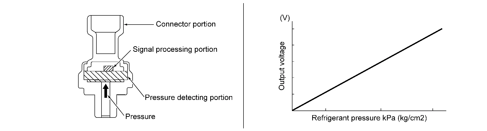
Refrigerant Pressure Sensor
The refrigerant pressure sensor is installed at the condenser of the air conditioner system. The sensor uses an electrostatic volume pressure transducer to convert refrigerant pressure to voltage. The voltage signal is sent to ECM, and ECM controls cooling fan system.
Stop Lamp Switch Brake Pedal Position Switch
Stop lamp switch and brake pedal position switch are installed to brake pedal bracket.
ECM detects the state of the brake pedal by those two types of input (ON/OFF signal).
| Brake pedal | Brake pedal position switch | Stop lamp switch |
|---|---|---|
| Released | ON | OFF |
| Depressed | OFF | ON |
Stop/Start Off Switch
FUNCTIONS WITHIN THE SYSTEM
When the stop/start OFF switch is pressed, the internal indicator lamp (on information display) turns ON, and the stop/start system can be canceled.
INDIVIDUAL FUNCTION WITHIN THE SYSTEM
-
Turns the internal switch ON/OFF, controlling the stop/start OFF switch signal that is input into the BCM.
-
Turns the internal indicator lamp (on the information display) ON/OFF.
INDIVIDUAL OPERATION
-
When the stop/start OFF switch is turned ON, the internal indicator lamp (on the information display) turns ON, and the stop/start system does not operate.
-
When the stop/start OFF switch is turned OFF, the internal indicator lamp turns (on the information display) OFF, and the stop/start system operates.
COMPONENT PARTS LOCATION
The stop/start switch is set on the upper part of the center console.
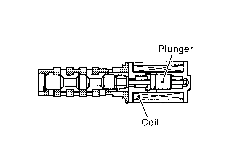
VIAS Control Solenoid Valve 1 and 2
The VIAS control solenoid valve cuts the intake manifold vacuum signal for power valve control. It responds to ON/OFF signals from the ECM. When the solenoid is OFF, the vacuum signal from the intake manifold is cut. When the ECM sends an ON signal the coil pulls the plunger downward and sends the vacuum signal to the power valve actuator.

Nissan Pathfinder (R53) 2022-2026 Service Manual
Contact Us
Nissan Pathfinder Info Center
Email: info@nipathfinder.com
Phone: +1 (800) 123-4567
Address: 123 Pathfinder Blvd, Nashville, TN 37214, USA
Working Hours: Mon–Fri, 9:00 AM – 5:00 PM (EST)
