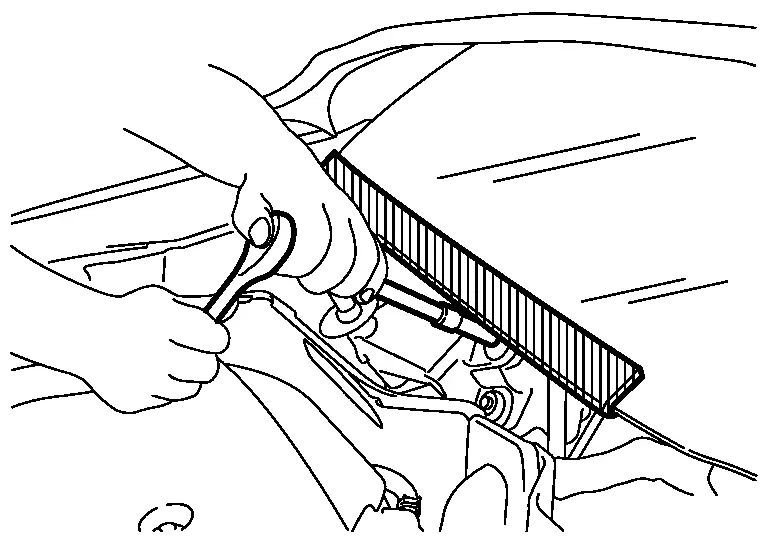
Nissan Pathfinder: Driveline - Transfer: Ty92b
- Precautions
- Preparation
- Ecu Diagnosis Information. Awd Control Unit ➤
- Periodic Maintenance. Transfer Oil
- Unit Removal and Installation. Transfer Assembly ➤
- Service Data and Specifications (SDS)
Precautions Nissan Pathfinder Fifth generation
Precaution for Supplemental Restraint System (SRS) "AIR BAG" and "SEAT BELT PRE-TENSIONER"
The Supplemental Restraint System such as “AIR BAG” and “SEAT BELT PRE-TENSIONER”, used along with a front seat belt, helps to reduce the risk or severity of injury to the driver and front passenger for certain types of collisions.
Information necessary to service the system safely is included in the “SRS AIR BAG” and “SEAT BELT” sections of this Service Manual.
WARNING:
Always observe the following items for preventing accidental activation:
-
To avoid rendering the SRS inoperative, which could increase the risk of personal injury or death in the event of a collision that would result in air bag inflation, it is recommended that all maintenance and repair be performed by an authorized NISSAN/INFINITI dealer.
-
Improper repair, including incorrect removal and installation of the SRS, can lead to personal injury caused by unintentional activation of the system. For removal of Spiral Cable and Air Bag Module, see “SRS AIR BAG”.
-
Never use electrical test equipment on any circuit related to the SRS unless instructed to in this Service Manual. SRS wiring harnesses can be identified by yellow and/or orange harnesses or harness connectors.
PRECAUTIONS WHEN USING POWER TOOLS (AIR OR ELECTRIC) AND HAMMERS
WARNING:
Always observe the following items for preventing accidental activation:
-
When working near the Air Bag Diagnosis Sensor Unit or other Air Bag System sensors with the ignition/power switch ON or engine running, never use air or electric power tools or strike near the sensor(s) with a hammer. Heavy vibration could activate the sensor(s) and deploy the air bag(s), possibly causing serious injury.
-
When using air or electric power tools or hammers, always switch the ignition/power switch OFF, disconnect the 12V battery or batteries, and wait at least 3 minutes before performing any service.
Precaution for Procedure without Cowl Top Cover
When performing the procedure after removing cowl top cover, cover the lower end of windshield with urethane, etc to prevent damage to windshield.
Precaution for Battery Service
Before disconnecting the battery, lower both the driver and passenger windows. This will prevent any interference between the window edge and the Nissan Pathfinder vehicle when the door is opened/closed. During normal operation, the window slightly raises and lowers automatically to prevent any window to Nissan Pathfinder vehicle interference. The automatic window function will not work with the battery disconnected.
Service Notice or Precautions for Transfer
-
After overhaul refill the transfer with new transfer oil.
-
Check the oil level or replace the oil only with the Nissan Pathfinder vehicle parked on level surface.
-
During removal or installation, keep inside of transfer clear of dust or dirt.
-
Replace all tires at the same time. Always use tires of the proper size and the same brand and pattern. Fitting improper size and unusual wear tires applies excessive force to Nissan Pathfinder vehicle mechanism and can cause longitudinal vibration.
-
Disassembly should be done in a clean work area.
-
Before proceeding with disassembly, thoroughly clean the transfer. It is important to prevent the internal parts from becoming contaminated by dirt or other foreign matter.
-
Check for the correct installation status prior to removal or disassembly. If matching marks are required, be certain they do not interfere with the function of the parts when applied.
-
All parts should be carefully cleaned with a general purpose, non-flammable solvent before inspection or reassembly.
-
Check the appearance of the disassembled parts for damage, deformation, and unusual wear. Replace them with a new one if necessary.
-
Gaskets, seals, O-rings and lock nuts should be replaced any time when the transfer is disassembled.
-
In principle, tighten bolts or nuts gradually in several steps working diagonally from inside to outside. If a tightening sequence is specified, use it.
-
Observe the specified torque when assembling.
-
Clean and flush the parts sufficiently and blow-dry them.
-
Be careful not to damage sliding surfaces and mating surfaces.
-
Use lint-free cloth or towels for wiping parts clean. Common shop rags can leave fibers that could interfere with the operation of the transfer.
-
Do not turn the assembled transfer assembly upside down.
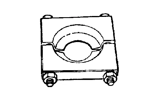
Preparation Nissan Pathfinder 2026
Special Service Tool
The actual shape of the tools may differ from those illustrated here.
|
Tool number (TechMate No.) Tool name | Description | |
|---|---|---|
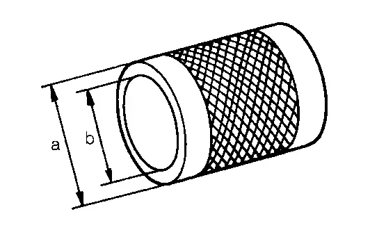
|
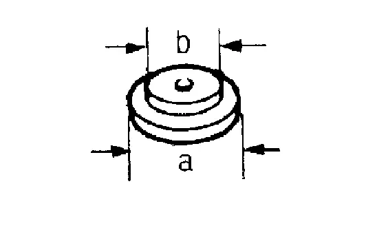
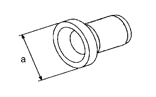
ST33061000 (NI-8107-2) Drift |
|
Removing ring gear bearing (left) inner race (transfer case side) a: 38 mm (1.50 in) dia. b: 28.5 mm (1.122 in) dia. |
|
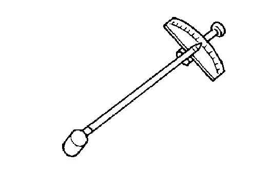
ST3127S000 (NI-25765-A) Preload gauge |
|
Measuring preload torque |
|
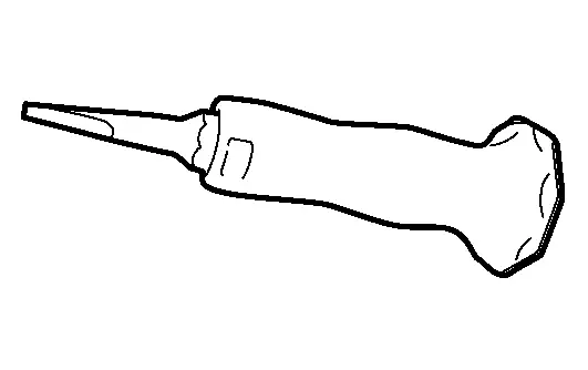
— (NI-52982) Lock nut chisel (Cape chisel) |
|
Removing wheel hub lock nut |
|
— (NI-53127) Transfer case dust seal installer |
|
Installing transfer case dust seal |
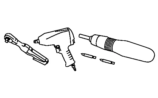
Commercial Service Tool
| Tool name | Description | |
|---|---|---|
| Power tool |
|
Loosening nuts and bolts and nuts |
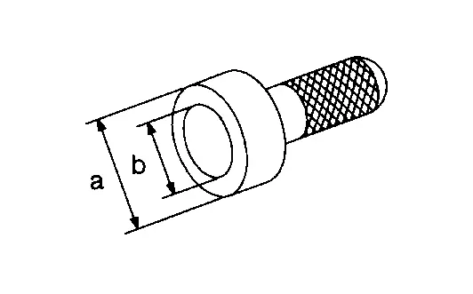
| Drift |
|
Removing gear ring bearing inner race (adapter case side) a: 52 mm (2.05 in) dia. b: 44 mm (1.73 in) dia. |
| Drift |
|
Installing side oil seal (installing transfer case oil seal) a: 56.5 mm (2.224 in) dia. b: 48 mm (1.89 in) dia. |
| Drift |
|
Installing oil seal (installing pinion bearing seal) a: 78 mm (3.07 in) dia. b: 68 mm (2.68 in) dia. |
| Drift |
|
Installing side oil seal (installing transfer cover oil seal) a: 70 mm (2.76 in) dia. b: 60 mm (2.36 in) dia. |
| Bearing separator |
|
|
| Drift |
|
Installing ring gear bearing (left) inner race (transfer case side) a: 58 mm (2.28 in) dia. b: 55 mm (2.17 in) dia. |
| Drift |
|
Installing ring gear bearing (right) inner race (transfer cover side) a: 62 mm (2.44 in) dia. b: 58 mm (2.28 in) dia. |
| Drift |
|
Installing ring gear bearing (left) outer race (transfer case side) a: 73.5 mm (2.894 in) dia. |
| Drift |
|
Installing ring gear bearing (right) outer race (transfer cover side) a: 87 mm (3.43 in) dia. |
| Drift |
|
Removing drive pinion a: 20 mm (0.79 in) dia. |
| Drift |
|
Installing pinion bearing a: 50 mm (1.97 in) dia. b: 41 mm (1.61 in) dia. |
| Drift |
|
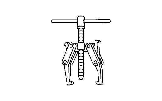
Installing companion flange a: 40 mm (1.57 in) dia. b: 25 mm (0.98 in) dia. |
| Puller |
|
Removing ring gear bearing (left) inner race (transfer case side) |
| Drift |
|
Installing ring gear a: 72.5 mm (2.85 in) dia. b: 65.4 mm (2.58 in) dia. |
| Lock nut crimp punch (Cold chisel) |
|
Installing wheel hub lock nut a: 5 mm (0.20 in) b: 7 mm (0.28 in) |


Always Replace with New Parts
| Never Reuse These Parts | Part # Prefix | For additional information: |
|---|---|---|
| Transfer cover dust seal | 33142A | TRANSFER COVER EXPLODED VIEW |
| Gasket | 33100Q, 33100QB | TRANSFER COVER EXPLODED VIEW |
| Transfer cover oil seal | 33142 | TRANSFER COVER EXPLODED VIEW |
| O-ring | 38343Y | TRANSFER COVER EXPLODED VIEW |
| Ring gear bearing (transfer cover side) | 38440QA | TRANSFER COVER EXPLODED VIEW |
| Gasket | 33100QA | TRANSFER COVER EXPLODED VIEW |
| Ring gear bearing (transfer case side) | 38440Q | TRANSFER COVER EXPLODED VIEW |
| Snap ring | 33138N | TRANSFER COVER EXPLODED VIEW |
| O-ring | 33119E | TRANSFER COVER EXPLODED VIEW |
| O-ring | 33386 | TRANSFER COVER EXPLODED VIEW |
| Pinion bearing assembly | 33158M | TRANSFER COVER EXPLODED VIEW |
| Oil seal | 38189X | TRANSFER COVER EXPLODED VIEW |
| Pinion lock nut | 32140H | TRANSFER COVER EXPLODED VIEW |
Ecu Diagnosis Information. Awd Control Unit ➤ Nissan Pathfinder SUV
Periodic Maintenance. Transfer Oil Nissan Pathfinder 2022
Inspection
TRANSFER OIL LEAKS
Check that transfer oil is not leaking from the transfer assembly or around it.
TRANSFER OIL LEVEL
CAUTION:
Do not start the engine while checking transfer oil level.
Remove front under cover. Refer to Removal and Installation.
Remove filler plug (1) and gasket.
![]()
|
|
: Front |
Transfer oil level (A) should be level with bottom of filler plug hole. Add transfer oil if necessary. Refer to Fluids and Lubricants (United States and Canada) or Fluids and Lubricants (Mexico).
Set a new gasket onto the filler plug, and install it in the transfer and tighten to the specified torque. Refer to Exploded View.
CAUTION:
Do not reuse gasket.
Draining
CAUTION:
Do not start engine while working.
Run the vehicle to warm up the transfer unit sufficiently.
Stop the engine.
Remove front under cover. Refer to Removal and Installation.
Remove drain plug (1) and gasket and drain the transfer oil.
![]()
|
|
: Front |
Set a new gasket onto filler plug, and install it in the transfer and tighten to specified torque. Refer to Exploded View.
CAUTION:
Do not reuse gasket.
Refilling
CAUTION:
Do not start engine while checking transfer oil level.
Remove front under cover. Refer to Removal and Installation.
Remove filler plug (1) and gasket.
![]()
Fill with new transfer oil to the specified level near the filler plug hole.
|
|
: Front |
| Transfer oil grade and viscosity | : Refer to Fluids and Lubricants (United States and Canada) or Fluids and Lubricants (Mexico). |
| Transfer oil capacity | : Refer to General Specifications. |
Set a new gasket onto filler plug, and install it in the transfer and tighten to specified torque. Refer to Exploded View.
CAUTION:
Do not reuse gasket.
Unit Removal and Installation. Transfer Assembly ➤ Nissan Pathfinder SUV
Service Data and Specifications (SDS) Nissan Pathfinder
General Specifications
 (US pt, Imp pt)
| Applied model | VQ35DD | ||||
|---|---|---|---|---|---|
| 9AT | |||||
| Transfer model | TY92B | ||||
| Oil Type | Refer to Fluids and Lubricants (United States and Canada) or Fluids and Lubricants (Mexico). | ||||
| Oil capacity (Approx.) | 0.31 (5/8 pt, 1/2 pt) | ||||
| Gear ratio | 0.404 | ||||
| Number of teeth | Ring gear | 42 | |||
| Drive pinion | 17 | ||||
Preload Torque
Unit: N·m (kg-m, in-lb)
| Item | Standard | ||
|---|---|---|---|
| Pinion bearing preload | 0.25 – 1.33 (0.03 – 0.14, 2.0 – 12.0) | ||
| Total preload | With all oil seals | P1 + 0.7 – 1.0 (0.08 – 0.1, 7.0 – 8.0) | |
| Without oil seals (for transfer cover and transfer case) | P1 + 0.5 – 0.8 (0.06 – 0.08, 5.0 – 7.0) | ||
Backlash
Unit: mm (in)
| Item | Standard |
|---|---|
| Ring gear to drive pinion | 0.1 – 0.15 (0.004 – 0.0059) |
Companion Flange Runout
Unit: mm (in)
| Item | Limit |
|---|---|
| Companion flange face (inner side of the propeller shaft mounting bolt holes) | 0.15 (0.0059) |
| Inside of companion flange (socket diameter) | 0.1 (0.004) |

Nissan Pathfinder (R53) 2022-2026 Service Manual
Transfer: Ty92b
- Precautions
- Preparation
- Ecu Diagnosis Information. Awd Control Unit ➤
- Periodic Maintenance. Transfer Oil
- Unit Removal and Installation. Transfer Assembly ➤
- Service Data and Specifications (SDS)
Contact Us
Nissan Pathfinder Info Center
Email: info@nipathfinder.com
Phone: +1 (800) 123-4567
Address: 123 Pathfinder Blvd, Nashville, TN 37214, USA
Working Hours: Mon–Fri, 9:00 AM – 5:00 PM (EST)
