Nissan Pathfinder: Front Suspension - Removal and Installation
Front Coil Spring and Strut Nissan Pathfinder 5th Gen
Exploded View
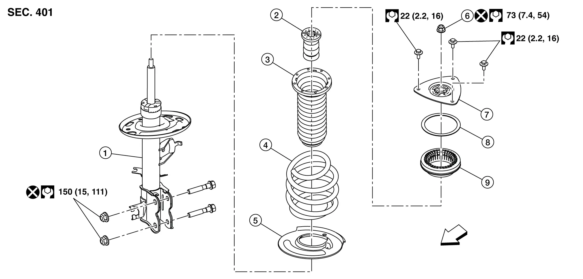
| 1. | Strut | 2. | Bound bumper | 3. | Upper rubber seat |
| 4. | Spring | 5. | Lower rubber seat | 6. | Piston rod lock nut |
| 7. | Strut mount insulator | 8. | Seal | 9. | Strut mount bearing |
 |
Front |
Removal and Installation
REMOVAL
Remove the cowl access panel . Refer to Exploded View.
Remove the front coil spring and strut mounting insulator covers.
Remove the upper front coil spring and strut mounting insulator bolts using power tool.
Remove the front wheels and tires using power tool. Refer to Removal and Installation.
Remove the wheel sensor harness from the front coil spring and strut.
Remove the brake hose lock plate (A).
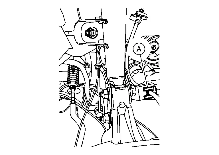
Remove the stabilizer connecting rod nut (A) from the front coil spring and strut. Position the stabilizer connecting rod (1) aside. Refer to Exploded View.
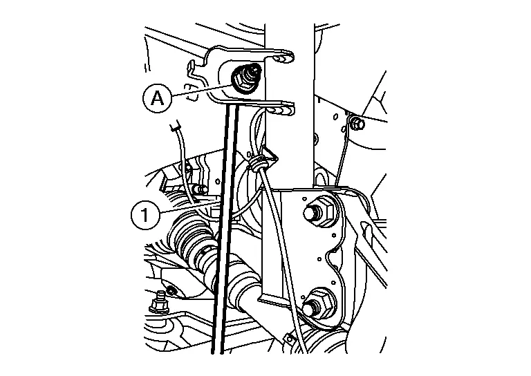
Remove the lower strut nuts and bolts.
CAUTION:
Do not reuse lower strut nuts.
Remove the front coil spring and strut.
INSTALLATION
Installation is in the reverse order of removal.
CAUTION:
Do not reuse lower strut nuts.
-
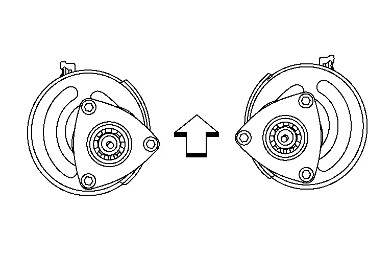
Be sure strut mount insulator is positioned as shown.

: Front -
Check the wheel alignment. Refer to Inspection.
-
Adjust the neutral position of the steering angle sensor. Refer to Description.
Disposal
Set strut assembly horizontally with the piston rod fully extended.
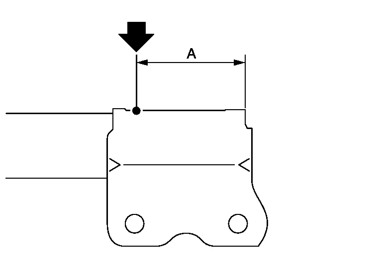
Drill 2 – 3 mm (0.08 – 0.12 in) hole at the position (
 ) from top as shown to release gas gradually.
CAUTION:
-
Wear eye protection (safety glasses).
-
Wear gloves.
-
Be careful with metal chips or oil blown out by the compressed gas.
 NOTE:
NOTE:
-
Drill vertically in this direction (
 ) directly to the outer tube avoiding brackets.
 -
The gas is clear, colorless, odorless, and harmless.
| (A) | : 20 – 30 mm (0.79 – 1.18 in) |
Position the drilled hole downward and drain oil by moving the piston rod several times.
CAUTION:
Dispose of drained oil according to the law and local regulations.
Transverse Link Nissan Pathfinder Fifth generation
Exploded View
![]()
| 1. | Transverse link | 2. | Front suspension member |
|
Front |
Removal and Installation
REMOVAL
Remove the steering knuckle and hub. Refer to Removal and Installation.
Remove transverse link nuts and bolts. Refer to Exploded View.
Remove transverse link from suspension member.
INSPECTION AFTER REMOVAL
Check the following items, and replace the parts if necessary.
Transverse Link
-
Transverse link for deformation, cracks or damage.
-
Bushing for complete separation. (If completely separated, inner metal can be pulled out from transverse link.)
-
Bushing for leakage.
-
Ball joint boot for cracks or other damage, and also for grease leakage.
Swinging Torque Inspection
-
Move ball stud at least ten times by hand to check for smooth movement.
-
Hook a tool (A) at pinch bolt location. Confirm measurement value is within specifications when ball stud begins moving.
Tool number : — (NI-44372) Swinging torque Refer to Ball Joint. -
If swinging torque exceeds standard range, replace transverse link.
-
Rotating Torque Inspection
-
Move ball stud at least ten times by hand to check for smooth movement.
-
Confirm measurement value is within specifications when the ball stud begins rotating.
Rotating torque Refer to Ball Joint. -
If the rotating torque exceeds the standard range, replace transverse link.
-
Axial End Play Inspection
-
Move ball stud at least ten times by hand to check for smooth movement.
-
Move tip of ball stud in axial direction to check for looseness.
-
If there is axial end play, replace transverse link assembly.
-
INSTALLATION
Installation is in the reverse order of removal.
CAUTION:
Do not reuse transverse link nuts.
-
Perform final tightening of bolts and nuts at the front suspension member, under unladen conditions with tires on level ground.
-
Check wheel alignment. Refer to Inspection.
-
Adjust neutral position of steering angle sensor. Refer to Description.
Front Stabilizer Nissan Pathfinder SUV
Exploded View
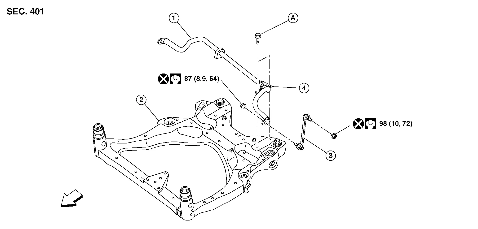
| 1. | Stabilizer bar | 2. | Front suspension member | 3. | Connecting rod |
| A. | Refer to Removal and Installation. |
 |
Front |
Removal and Installation
REMOVAL
Remove steering gear Removal and Installation.
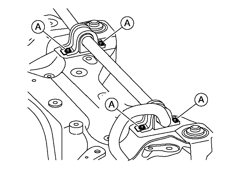
Remove the bolts (A) from the stabilizer clamp, and then remove the stabilizer clamp and the stabilizer bushing from the front suspension member.
INSTALLATION
Install stabilizer bar clamp so that notch (A) is facing front of vehicle (
 ).
).
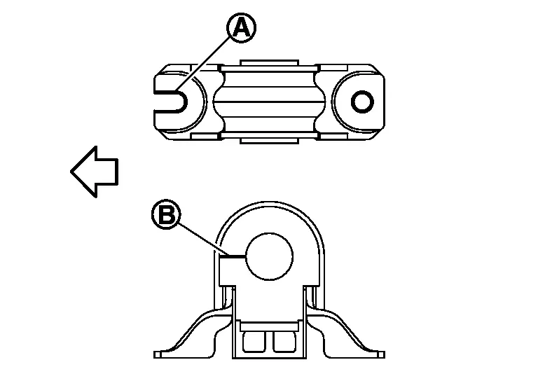
Install stabilizer bar bushing so that slit (B) is facing front of Nissan Pathfinder vehicle (
 ).
).
Install the stabilizer bar clamp bolts in the sequence shown.
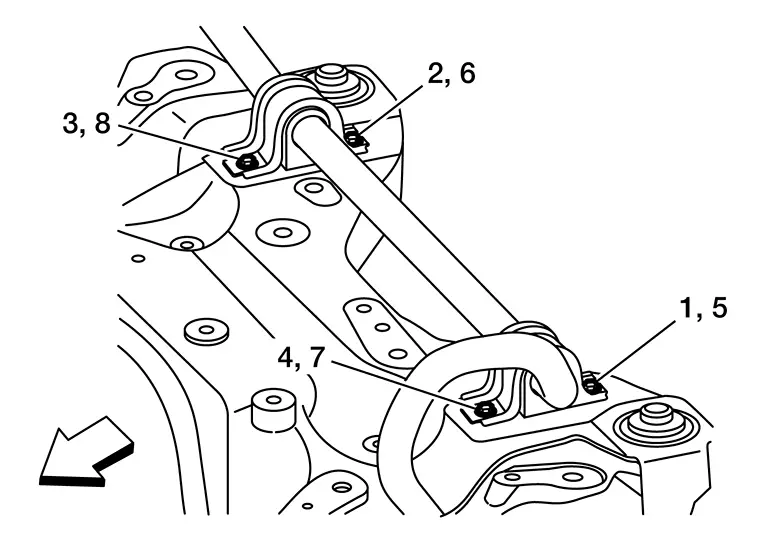
| Temporary tightening | : 1 - 4 |
| Final tightening (Specified torque) | : 5 - 8 |
| Specified torque | : 53 N·m (5.4 kg-m, 39 ft-lb) |
 |
: Front |
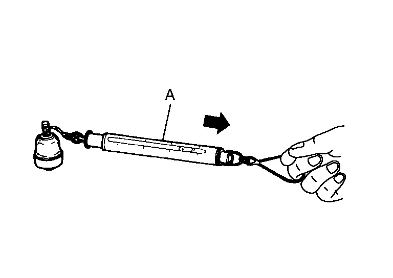
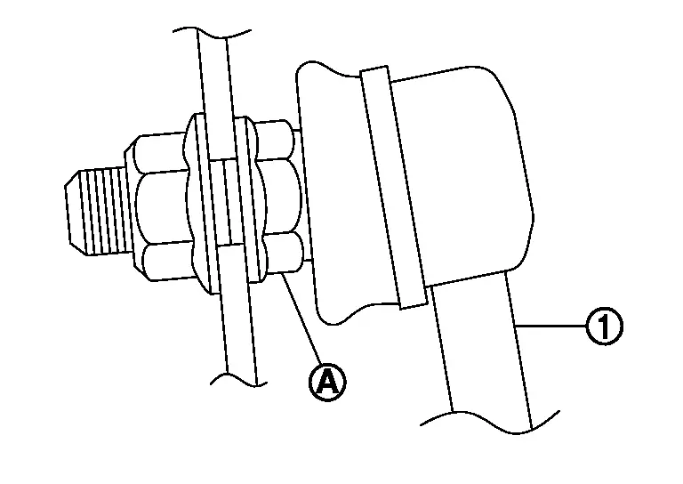
To connect the stabilizer bar connecting rod (1), tighten the nut while holding the hexagonal part (A) on the stabilizer bar connecting rod.
Perform the final tightening of the nuts and bolts under unladen conditions with the tires on level ground.
-
Check the wheel alignment. Refer to Inspection.
-
Adjust the neutral position of the steering angle sensor. Refer to Description.
CAUTION:
Do not reuse connecting rod nuts.
Steering Knuckle Nissan Pathfinder 2026
Exploded View
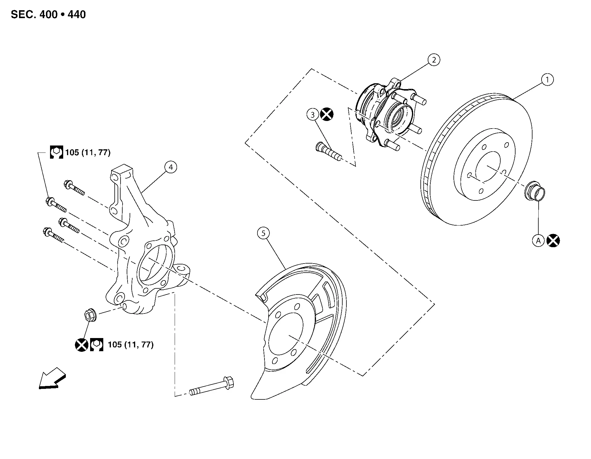
| 1. | Disc brake rotor | 2. | Wheel hub and bearing | 3. | Wheel stud |
| 4. | Steering knuckle | 5. | Splash guard | A. | Refer to Installation |
 |
Front |
Removal and Installation
REMOVAL
Remove the wheel hub and bearing. Refer to Removal and Installation.
Separate the outer socket from the steering knuckle. Refer to Exploded View.
Remove the nut from the lower ball joint pinch bolt.
CAUTION:
Do not reuse the lower ball joint pinch nut.
Remove lower strut bolts at steering knuckle. Refer to Exploded View.
CAUTION:
Do not reuse the lower strut nuts.
Remove lower ball joint pinch bolt and separate steering knuckle from transverse link.
INSPECTION AFTER REMOVAL
Check for deformity, cracks and damage on each part, replace if necessary.
Ball Joint Inspection
-
Check for boot breakage, axial looseness, and torque of transverse link ball joint and repair as necessary.
INSTALLATION
Installation is in the reverse order of removal.
CAUTION:
-
Do not reuse the lower strut nuts.
-
Do not reuse the wheel hub lock nut.
-
Do not reuse lower ball joint pinch nut
-
Check the wheel alignment. Refer to Inspection.
-
Adjust the neutral position of the steering angle sensor. Refer to Description.

Nissan Pathfinder (R53) 2022-2026 Service Manual
Removal and Installation
Contact Us
Nissan Pathfinder Info Center
Email: info@nipathfinder.com
Phone: +1 (800) 123-4567
Address: 123 Pathfinder Blvd, Nashville, TN 37214, USA
Working Hours: Mon–Fri, 9:00 AM – 5:00 PM (EST)
