Nissan Pathfinder: Dtc/circuit Diagnosis (B20c7-11 A/c Clutch ... B24a6-11 in-Vehicle Sensor)
- B20c7-11 A/c Clutch
- B20c7-15 A/c Clutch
- B2480-93 Rear Air Mix Door Motor
- B24a0-49 A/c Auto Amp.
- B24a1-16 A/c Amp. Power Supply
- B24a2-55 Configuration Not Implement
- B24a4-11 Intake Sensor
- B24a4-15 Intake Sensor
- B24a6-11 in-Vehicle Sensor
B20c7-11 A/c Clutch Nissan Pathfinder R53
DTC Description
DTC DETECTION LOGIC
| DTC No. |
CONSULT screen terms (Trouble diagnosis content) | DTC detection condition | ||
|---|---|---|---|---|
| B20C7–11 |
A/C clutch (A/C clutch) |
[CIRCUIT SHORT TO GROUND] | Diagnosis condition | When A/C switch is ON |
| Signal (Terminal) | Magnetic clutch ON signal | |||
| Threshold | Magnetic clutch ON signal circuit has a short to ground | |||
| Diagnosis delay time | 1 second or more | |||
POSSIBLE CAUSE
-
Harness or connectors (magnetic clutch ON signal circuit is shorted to ground)
-
IPDM E/R
FAIL-SAFE
Inhibit A/C compressor (magnetic clutch) operation
DTC CONFIRMATION PROCEDURE
PERFORM SELF-DIAGNOSIS
 CONSULT
-
Start the engine.
-
A/C switch ON.
-
Select “Self Diagnostic Result” mode of “IPDM E/R”.
-
Check DTC.
Is DTC detected?
YES>>Refer to DTC Diagnosis Procedure.
NO>>To check malfunction symptom before repair: Refer to Intermittent Incident.
NO>>Confirmation after repair: Inspection End.
DTC Diagnosis Procedure
CHECK MAGNETIC CLUTCH ON SIGNAL CIRCUIT FOR SHORT
-
Ignition switch OFF.
-
Disconnect IPDM E/R connector and A/C compressor connector.
-
Check continuity between IPDM E/R harness connector and ground.
| IPDM E/R | — | Continuity | |
|---|---|---|---|
| Connector | Terminal | ||
| F24 | 65 | Ground | No |
Is the inspection result normal?
YES>>Replace IPDM E/R. Refer to Removal and Installation.
NO>>Repair harness or connector.
B20c7-15 A/c Clutch Nissan Pathfinder 5th Gen
DTC Description
DTC DETECTION LOGIC
| DTC No. |
CONSULT screen terms (Trouble diagnosis content) | DTC detection condition | ||
|---|---|---|---|---|
| B20C7–15 |
A/C clutch (A/C clutch) |
[CIRC SHORT TO BATT OR OPEN] | Diagnosis condition | When A/C switch is ON |
| Signal (Terminal) | Magnetic clutch ON signal | |||
| Threshold | Magnetic clutch ON signal circuit has a short to power or open | |||
| Diagnosis delay time | 1 second or more | |||
POSSIBLE CAUSE
-
Harness or connectors (magnetic clutch ON signal circuit is shorted to battery or open)
-
IPDM E/R
FAIL-SAFE
Inhibit A/C compressor (magnetic clutch) operation
DTC CONFIRMATION PROCEDURE
PERFORM SELF-DIAGNOSIS
 CONSULT
-
Start the engine.
-
A/C switch ON.
-
Select “Self Diagnostic Result” mode of “IPDM E/R”.
-
Check DTC.
Is DTC detected?
YES>>Refer to DTC Diagnosis Procedure.
NO>>To check malfunction symptom before repair: Refer to Intermittent Incident.
NO>>Confirmation after repair: Inspection End.
DTC Diagnosis Procedure
CHECK MAGNETIC CLUTCH ON SIGNAL CIRCUIT FOR OPEN
-
Ignition switch OFF.
-
Disconnect IPDM E/R connector and A/C compressor connector.
-
Check continuity between IPDM E/R harness connector and A/C compressor harness connector.
| IPDM E/R | A/C compressor | Continuity | ||
|---|---|---|---|---|
| Connector | Terminal | Connector | Terminal | |
| F24 | 65 | F3 | 1 | Yes |
Is the inspection result normal?
YES>>GO TO 2.
NO>>Repair harness or connector.
CHECK MAGNETIC CLUTCH ON SIGNAL CIRCUIT FOR SHORT
Check voltage between IPDM E/R harness connector and ground.
| + | − |
Voltage (Approx.) | |
|---|---|---|---|
| IPDM E/R | |||
| Connector | Terminal | ||
| F24 | 65 | Ground | 0 V |
Is the inspection result normal?
YES>>GO TO 3.
NO>>Repair harness or connector.
CHECK MAGNETIC CLUTCH GROUND CIRCUIT FOR OPEN
Check continuity between A/C compressor harness connector and ground.
| A/C compressor | — | Continuity | |
|---|---|---|---|
| Connector | Terminal | ||
| F3 | 2 | Ground | Yes |
Is the inspection result normal?
YES>>Replace IPDM E/R. Refer to Removal and Installation.
NO>>Repair harness or connector.
B2480-93 Rear Air Mix Door Motor Nissan Pathfinder
DTC Description
DTC DETECTION LOGIC
 NOTE:
NOTE:
If all of door motors DTC (B2480-93*, B24F5-93, B24F6-93, B24F7-93, B24F8-93) are detected, check “DOOR MOTOR”. Refer to Diagnosis Procedure.
*: With rear air control
| DTC No. |
CONSULT screen terms (Trouble diagnosis content) | DTC detection condition | |
|---|---|---|---|
| B2480-93 |
Rear air mix door motor (Rear air mix door motor) |
Diagnosis condition | Ignition switch ON |
| Signal (Terminal) | LIN (door motor) signal | ||
| Threshold | Drive error of air mix door motor (rear) is detected | ||
| Diagnosis delay time | 1 second or more | ||
POSSIBLE CAUSE
-
Harness and connector [air mix door motor (rear) circuit is open or shorted to ground]
-
Air mix door motor (rear) installation condition
-
Air mix door motor (rear)
-
A/C auto amp.
FAIL-SAFE
—
DTC CONFIRMATION PROCEDURE
PERFORM SELF-DIAGNOSIS
 CONSULT
-
Start the engine.
-
Select “Self Diagnostic Result” mode of “HVAC”.
-
Check DTC.
Is DTC detected?
YES>>Refer to DTC Diagnosis Procedure.
NO>>To check malfunction symptom before repair: Refer to Intermittent Incident.
NO>>Confirmation after repair: Inspection End.
DTC Diagnosis Procedure
CHECK AIR MIX DOOR MOTOR (REAR) POWER SUPPLY
-
Ignition switch ON.
-
Check voltage between air mix door motor (rear) harness connector and ground.
| Air mix door motor (rear) | — |
Voltage (Approx.) | |
|---|---|---|---|
| Connector | Terminal | ||
| B156 | 1 | Ground | Battery voltage |
Is the inspection result normal?
YES>>GO TO 2.
NO>>GO TO 5.
CHECK AIR MIX DOOR MOTOR (REAR) GROUND CIRCUIT FOR OPEN
-
Ignition switch OFF.
-
Disconnect air mix door motor (rear) connector.
-
Check continuity between air mix door motor (rear) harness connector and ground.
Air mix door motor (rear) — Continuity Connector Terminal B156 2 Ground Yes
Is the inspection result normal?
YES>>GO TO 3.
NO>>Repair harness or connector.
CHECK AIR MIX DOOR MOTOR (REAR) LIN SIGNAL CIRCUIT
-
Connect air mix door motor (rear) connector.
-
Ignition switch ON.
-
Confirm output waveform between air mix door motor (rear) harness connector and ground with oscilloscope.
Air mix door motor (rear) — Output waveform Connector Terminal B156 3 Ground 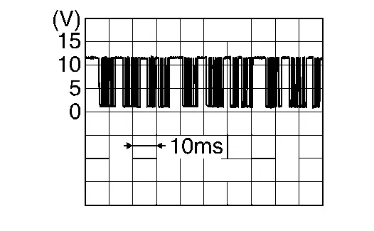
Is the inspection result normal?
YES>>GO TO 4.
NO>>GO TO 6.
CHECK INSTALLATION OF AIR MIX DOOR MOTOR (REAR)
Check air mix door motor (rear) is properly installed. Refer to Exploded View.
Is the inspection result normal?
YES>>Replace air mix door motor (rear). Refer to Removal and Installation - Air Mix Door Motor (Rear).
NO>>Repair or replace malfunctioning part.
CHECK AIR MIX DOOR MOTOR (REAR) POWER SUPPLY CIRCUIT FOR OPEN
-
Ignition switch OFF.
-
Disconnect air mix door motor (rear) connector and A/C auto amp. connector.
-
Check continuity between air mix door motor (rear) harness connector and A/C auto amp. harness connector.
Air mix door motor (rear) A/C auto amp. Continuity Connector Terminal Connector Terminal B156 1 M50 1 Yes
Is the inspection result normal?
YES>>Replace A/C auto amp. Refer to Removal and Installation.
NO>>Repair harness or connector.
CHECK AIR MIX DOOR MOTOR (REAR) LIN SIGNAL CIRCUIT FOR OPEN
-
Ignition switch OFF.
-
Disconnect air mix door motor (rear) connector and A/C auto amp. connector.
-
Check continuity between air mix door motor (rear) harness connector and A/C auto amp. harness connector.
Air mix door motor (rear) A/C auto amp. Continuity Connector Terminal Connector Terminal B156 3 M50 2 Yes
Is the inspection result normal?
YES>>Replace A/C auto amp. Refer to Removal and Installation.
NO>>Repair harness or connector.
B24a0-49 A/c Auto Amp. Nissan Pathfinder SUV
DTC Description
DTC DETECTION LOGIC
| DTC No. |
CONSULT screen terms (Trouble diagnosis content) | DTC detection condition | |
|---|---|---|---|
| B24A0-49 |
A/C AUTO AMP. (Air conditioning automatic amplifier) |
Diagnosis condition | Ignition switch ON |
| Signal (Terminal) | — | ||
| Threshold | A malfunction is detected in A/C auto amp. internal EEPROM memory functions. | ||
| Diagnosis delay time | 2 second or more | ||
POSSIBLE CAUSE
A/C auto amp.
FAIL-SAFE
—
DTC CONFIRMATION PROCEDURE
PERFORM SELF-DIAGNOSIS
 CONSULT
-
Ignition switch ON.
-
Select “Self Diagnostic Result” mode of “HVAC”.
-
Check DTC.
Is DTC detected?
YES>>Refer to DTC Diagnosis Procedure.
NO>>To check malfunction symptom before repair: Refer to Intermittent Incident.
NO>>Confirmation after repair: Inspection End.
DTC Diagnosis Procedure
REPLACE A/C AUTO AMP.
Replace A/C auto amp. Refer to Removal and Installation.
>>
Inspection End.
B24a1-16 A/c Amp. Power Supply Nissan Pathfinder R53
DTC Description
DTC DETECTION LOGIC
| DTC No. |
CONSULT screen terms (Trouble diagnosis content) | DTC detection condition | |
|---|---|---|---|
| B24A1-16 |
A/C AUTO AMP. POWER SUPPLY (Air conditioning automatic amplifier power supply) |
Diagnosis condition | Ignition switch ON |
| Signal (Terminal) | Accessory power supply | ||
| Threshold | Open or shorted to ground | ||
| Diagnosis delay time | 30 seconds or more | ||
POSSIBLE CAUSE
-
A/C auto amp.
-
Harness or connector (accessory power supply circuits is open or shorted to ground)
FAIL-SAFE
—
DTC CONFIRMATION PROCEDURE
PERFORM SELF-DIAGNOSIS
 CONSULT
-
Ignition switch ON.
-
Select “Self Diagnostic Result” mode of “HVAC”.
-
Check DTC.
Is DTC detected?
YES>>Refer to DTC Diagnosis Procedure.
NO>>To check malfunction symptom before repair: Refer to Intermittent Incident.
NO>>Confirmation after repair: Inspection End.
DTC Diagnosis Procedure
CHECK A/C AUTO AMP. POWER SUPPLY AND GROUND CIRCUITS
Check A/C auto amp. power supply and ground circuits. Refer to Diagnosis Procedure.
Is the inspection result normal?
YES>>Replace A/C auto amp. Refer to Removal and Installation.
NO>>Repair or replace malfunctioning parts.
B24a2-55 Configuration Not Implement Nissan Pathfinder SUV
DTC Description
DTC DETECTION LOGIC
| DTC No. |
CONSULT screen terms (Trouble diagnosis content) | DTC detection condition | |
|---|---|---|---|
| B24A2-55 |
Configuration not implement (Configuration not implement) |
Diagnosis condition | Ignition switch ON |
| Signal (Terminal) | — | ||
| Threshold | Nissan Pathfinder Vehicle specification is not written | ||
| Diagnosis delay time | 2 seconds or more | ||
POSSIBLE CAUSE
Configuration is not completed
FAIL-SAFE
—
DTC CONFIRMATION PROCEDURE
PERFORM SELF-DIAGNOSIS
 CONSULT
-
Ignition switch ON.
-
Select “Self Diagnostic Result” mode of “HVAC”.
-
Check DTC.
Is DTC detected?
YES>>Refer to DTC Diagnosis Procedure.
NO>>To check malfunction symptom before repair: Refer to Intermittent Incident.
NO>>Confirmation after repair: Inspection End.
DTC Diagnosis Procedure
PERFORM CONFIGURATION
Perform configuration. Refer to Description.
>>
Inspection End.
B24a4-11 Intake Sensor Nissan Pathfinder SUV
DTC Description
DTC DETECTION LOGIC
| DTC No. |
CONSULT screen terms (Trouble diagnosis content) | DTC detection condition | |
|---|---|---|---|
| B24A4-11 |
INTAKE SENSOR (Intake sensor) |
Diagnosis condition | Ignition switch ON |
| Signal (Terminal) | Intake sensor signal | ||
| Threshold | The intake sensor recognition temperature is too high [more than 212°F (100°C)] | ||
| Diagnosis delay time | 2 second or more | ||
POSSIBLE CAUSE
-
Intake sensor
-
A/C auto amp.
-
Harness or connectors (the sensor circuit is shorted to ground)
FAIL-SAFE
—
DTC CONFIRMATION PROCEDURE
PERFORM DTC CONFIRMATION PROCEDURE
 CONSULT
-
Ignition switch ON.
-
Select “Self Diagnostic Result” mode of “HVAC” .
-
Check DTC.
Is DTC detected?
YES>>Refer to DTC Diagnosis Procedure.
NO>>To check malfunction symptom before repair: Refer to Intermittent Incident.
NO>>Confirmation after repair: Inspection End.
DTC Diagnosis Procedure
CHECK INTAKE SENSOR SIGNAL
-
Ignition switch ON.
-
Check voltage between A/C auto amp. harness connector.
A/C auto amp. Voltage
(Approx.)Connector Terminals + - M50 23 26 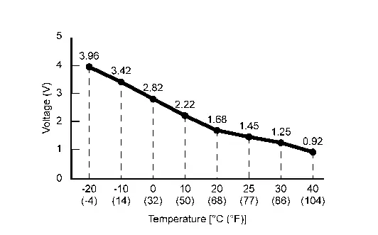
Is the inspection result normal?
YES>>Replace A/C auto amp. Refer to Removal and Installation.
NO>>GO TO 2.
CHECK INTAKE SENSOR POWER SUPPLY
-
Ignition switch OFF.
-
Disconnect intake sensor connector.
-
Ignition switch ON.
-
Check voltage between intake sensor harness connector and ground.
+ - Voltage
(Approx.)Intake sensor Connector Terminal M145 2 Ground 5 V
Is the inspection result normal?
YES>>GO TO 3.
NO>>GO TO 4.
CHECK INTAKE SENSOR
Check intake sensor. Refer to Component Inspection.
Is the inspection result normal?
YES>>Replace A/C auto amp. Refer to Removal and Installation.
NO>>Replace intake sensor. Refer to Removal and Installation.
CHECK INTAKE SENSOR POWER SUPPLY CIRCUIT FOR SHORT
-
Ignition switch OFF.
-
Disconnect A/C auto amp. connector.
-
Check continuity between intake sensor harness connector and ground.
Intake sensor — Continuity Connector Terminal M145 2 Ground No
Is the inspection result normal?
YES>>Replace A/C auto amp. Refer to Removal and Installation.
NO>>Repair harness or connector.
Component Inspection
CHECK INTAKE SENSOR
-
Ignition switch OFF.
-
Replace intake sensor. Refer to Removal and Installation.
-
Check resistance between intake sensor terminals. Refer to applicable table for the normal value.
Intake sensor Condition Resistance: kΩ Terminals Temperature: °F (°C) 1 2 −4 (−20) 23.60 14 (−10) 13.46 32 (0) 8.00 50 (10) 4.93 68 (20) 3.14 77 (25) 2.54 86 (30) 2.06 104 (40) 1.39
Is the inspection result normal?
YES>>Inspection End.
NO>>Replace intake sensor. Refer to Removal and Installation.
B24a4-15 Intake Sensor Nissan Pathfinder 5th Gen
DTC Description
DTC DETECTION LOGIC
| DTC No. |
CONSULT screen terms (Trouble diagnosis content) | DTC detection condition | |
|---|---|---|---|
| B24A4-15 |
INTAKE SENSOR (Intake sensor) |
Diagnosis condition | Ignition switch ON |
| Signal (Terminal) | Intake sensor signal | ||
| Threshold | The intake sensor recognition temperature is too low [less than -44°F (-42°C)] | ||
| Diagnosis delay time | 2 second or more | ||
POSSIBLE CAUSE
-
Intake sensor
-
A/C auto amp.
-
Harness or connectors (the sensor circuit is open or shorted to battery)
FAIL-SAFE
—
DTC CONFIRMATION PROCEDURE
PERFORM DTC CONFIRMATION PROCEDURE
 CONSULT
-
Ignition switch ON.
-
Select “Self Diagnostic Result” mode of “HVAC”.
-
Check DTC.
Is DTC detected?
YES>>Refer to DTC Diagnosis Procedure.
NO>>To check malfunction symptom before repair: Refer to Intermittent Incident.
NO>>Confirmation after repair: Inspection End.
DTC Diagnosis Procedure
CHECK INTAKE SENSOR SIGNAL
-
Ignition switch ON.
-
Check voltage between A/C auto amp. harness connector.
A/C auto amp. Voltage
(Approx.)Connector Terminals + - M50 23 26 
Is the inspection result normal?
YES>>Replace A/C auto amp. Refer to Removal and Installation.
NO>>GO TO 2.
CHECK INTAKE SENSOR POWER SUPPLY
-
Ignition switch OFF.
-
Disconnect intake sensor connector.
-
Ignition switch ON.
-
Check voltage between intake sensor harness connector and ground.
+ - Voltage
(Approx.)Intake sensor Connector Terminal M145 2 Ground 5 V
Is the inspection result normal?
YES>>GO TO 3.
NO>>GO TO 5.
CHECK INTAKE SENSOR GROUND CIRCUIT FOR OPEN
-
Ignition switch OFF.
-
Disconnect A/C auto amp. connector.
-
Check continuity between intake sensor harness connector and A/C auto amp. harness connector.
Intake sensor A/C auto amp. Continuity Connector Terminal Connector Terminal M145 1 M50 26 Yes
Is the inspection result normal?
YES>>GO TO 4.
NO>>Repair harness or connector.
CHECK INTAKE SENSOR
Check intake sensor. Refer to Component Inspection.
Is the inspection result normal?
YES>>Replace A/C auto amp. Refer to Removal and Installation.
NO>>Replace intake sensor. Refer to Removal and Installation.
CHECK INTAKE SENSOR POWER SUPPLY CIRCUIT FOR OPEN
-
Ignition switch OFF.
-
Disconnect A/C auto amp. connector.
-
Check continuity between intake sensor harness connector and A/C auto amp. harness connector.
Intake sensor A/C auto amp. Continuity Connector Terminal Connector Terminal M145 2 M50 23 Yes
Is the inspection result normal?
YES>>GO TO 6.
NO>>Repair harness or connector.
CHECK INTAKE SENSOR POWER SUPPLY CIRCUIT FOR SHORT
Check voltage between intake sensor harness connector and ground.
| + | - |
Voltage (Approx.) | |
|---|---|---|---|
| Intake sensor | |||
| Connector | Terminal | ||
| M145 | 2 | Ground | 0 V |
Is the inspection result normal?
YES>>Replace A/C auto amp. Refer to Removal and Installation.
NO>>Repair harness or connector.
Component Inspection
CHECK INTAKE SENSOR
-
Ignition switch OFF.
-
Replace intake sensor. Refer to Removal and Installation.
-
Check resistance between intake sensor terminals. Refer to applicable table for the normal value.
Intake sensor Condition Resistance: kΩ Terminals Temperature: °F (°C) 1 2 −4 (−20) 23.60 14 (−10) 13.46 32 (0) 8.00 50 (10) 4.93 68 (20) 3.14 77 (25) 2.54 86 (30) 2.06 104 (40) 1.39
Is the inspection result normal?
YES>>Inspection End.
NO>>Replace intake sensor. Refer to Removal and Installation.
B24a6-11 in-Vehicle Sensor Nissan Pathfinder R53
DTC Description
DTC DETECTION LOGIC
| DTC No. |
CONSULT screen terms (Trouble diagnosis content) | DTC detection condition | |
|---|---|---|---|
| B24A6-11 |
IN-Nissan Pathfinder Vehicle SENSOR (In-vehicle sensor) |
Diagnosis condition | Ignition switch ON |
| Signal (Terminal) | In-Nissan Pathfinder vehicle sensor signal | ||
| Threshold | The in-Nissan Pathfinder vehicle sensor recognition temperature is too high [more than 212°F (100°C)] | ||
| Diagnosis delay time | 2 second or more | ||
POSSIBLE CAUSE
-
Front in-vehicle sensor
-
A/C auto amp.
-
Harness or connectors (the sensor circuit is shorted to ground)
FAIL-SAFE
In-vehicle temperature is calculated as 77°F (25°C) and air conditioning system is controlled.
DTC CONFIRMATION PROCEDURE
PERFORM DTC CONFIRMATION PROCEDURE
 CONSULT
-
Ignition switch ON.
-
Select “Self Diagnostic Result” mode of “HVAC”.
-
Check DTC.
Is DTC detected?
YES>>Refer to DTC Diagnosis Procedure.
NO>>To check malfunction symptom before repair: Refer to Intermittent Incident.
NO>>Confirmation after repair: Inspection End.
DTC Diagnosis Procedure
CHECK FRONT IN-VEHICLE SENSOR SIGNAL
-
Ignition switch ON.
-
Check voltage between A/C auto amp. harness connector.
A/C auto amp. Voltage
(Approx.)Connector Terminals + - M60 48 78 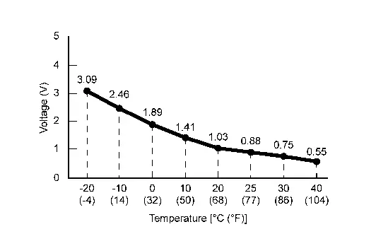
Is the inspection result normal?
YES>>Replace A/C auto amp. Refer to Removal and Installation.
NO>>GO TO 2.
CHECK FRONT IN-Nissan Pathfinder Vehicle SENSOR POWER SUPPLY
-
Ignition switch OFF.
-
Disconnect front in-vehicle sensor connector.
-
Ignition switch ON.
-
Check voltage between front in-Nissan Pathfinder vehicle sensor harness connector and ground.
+ - Voltage
(Approx.)Front in-Nissan Pathfinder vehicle sensor Connector Terminal M102 1 Ground 5 V
Is the inspection result normal?
YES>>GO TO 3.
NO>>GO TO 4.
CHECK FRONT IN-Nissan Pathfinder Vehicle SENSOR
Check front in-vehicle sensor. Refer to Component Inspection.
Is the inspection result normal?
YES>>Replace A/C auto amp. Refer to Removal and Installation.
NO>>Replace front in-Nissan Pathfinder vehicle sensor. Refer to Removal and Installation.
CHECK FRONT IN-Nissan Pathfinder Vehicle SENSOR POWER SUPPLY CIRCUIT FOR SHORT
-
Ignition switch OFF.
-
Disconnect A/C auto amp. connector.
-
Check continuity between front in-Nissan Pathfinder vehicle sensor harness connector and ground.
Front in-Nissan Pathfinder vehicle sensor — Continuity Connector Terminal M102 1 Ground No
Is the inspection result normal?
YES>>Replace A/C auto amp. Refer to Removal and Installation.
NO>>Repair harness or connector.
Component Inspection
CHECK FRONT IN-VEHICLE SENSOR
-
Ignition switch OFF.
-
Remove front in-Nissan Pathfinder vehicle sensor. Refer to Removal and Installation.
-
Check resistance between front in-vehicle sensor terminals. Refer to applicable table for the normal value.
Front in-Nissan Pathfinder vehicle sensor Condition Resistance: kΩ Terminals Temperature: °F (°C) 1 2 −4 (−20) 16.50 14 (−10) 9.92 32 (0) 6.19 50 (10) 3.99 68 (20) 2.65 77 (25) 2.19 86 (30) 1.81 104 (40) 1.27
Is the inspection result normal?
YES>>Inspection End.
NO>>Replace front in-Nissan Pathfinder vehicle sensor. Refer to Removal and Installation.

Nissan Pathfinder (R53) 2022-2026 Service Manual
Dtc/circuit Diagnosis (B20c7-11 A/c Clutch ... B24a6-11 in-Vehicle Sensor)
- B20c7-11 A/c Clutch
- B20c7-15 A/c Clutch
- B2480-93 Rear Air Mix Door Motor
- B24a0-49 A/c Auto Amp.
- B24a1-16 A/c Amp. Power Supply
- B24a2-55 Configuration Not Implement
- B24a4-11 Intake Sensor
- B24a4-15 Intake Sensor
- B24a6-11 in-Vehicle Sensor
Contact Us
Nissan Pathfinder Info Center
Email: info@nipathfinder.com
Phone: +1 (800) 123-4567
Address: 123 Pathfinder Blvd, Nashville, TN 37214, USA
Working Hours: Mon–Fri, 9:00 AM – 5:00 PM (EST)
