Nissan Pathfinder: Heater & Air Conditioning Control System - Dtc/circuit Diagnosis
- Power Supply and Ground Circuit
- Sunload Sensor
- Door Motor
- Front Blower Motor
- Rear Blower Motor
- Magnetic Clutch
- Ecv (electrical Control Valve)
- Rear Blower Motor Resistor
- 4020 B20c7-11 A/c Clutch
- 4020 B20c7-15 A/c Clutch
- 4020 B2480-93 Rear Air Mix Door Motor
- 4020 B24a0-49 A/c Auto Amp.
- 4020 B24a1-16 A/c Amp. Power Supply
- 4020 B24a2-55 Configuration Not Implement
- 4020 B24a4-11 Intake Sensor
- 4020 B24a4-15 Intake Sensor
- 4020 B24a6-11 in-Vehicle Sensor
- 4021 B24a6-15 in-Vehicle Sensor
- 4021 B24b4-02 A/c Control Comm
- 4021 B24c6-12 Blower Motor Control
- 4021 B24f5-93 Mode Door Motor
- 4021 U1ca1-08 A/c Switch Assembly Communication
- 4021 U1ca2-08 Door Motor Communication
- 4021 U1caa-02 Mode Door Motor
- 4021 U2140-87 Can Comm Err (ecm)
Power Supply and Ground Circuit Nissan Pathfinder SUV
A/c Auto Amp.
Diagnosis Procedure
CHECK A/C AUTO AMP. GROUND CIRCUIT FOR OPEN
-
Ignition switch OFF.
-
Disconnect A/C auto amp. connector.
-
Check continuity between A/C auto amp. harness connector and ground.
A/C auto amp. — Continuity Connector Terminal M60 58 Ground Yes
Is the inspection result normal?
YES>>GO TO 2.
NO>>Repair harness or connector.
CHECK FUSE
Check that the following fuse is not blown (open):
| Unit | Location | Fuse No. | Capacity |
|---|---|---|---|
| A/C auto amp. | Fuse block (J/B) | 40 | 10 A |
Is the fuse blown (open)?
YES>>Replace the blown fuse after repairing the affected circuit.
NO>>GO TO 3.
CHECK A/C AUTO AMP. POWER SUPPLY
-
Connect A/C auto amp. connector.
-
Check voltage between A/C auto amp. harness connector terminals.
A/C auto amp. Condition Voltage
(Approx.)Connector Terminals + − M60 60 58 Ignition switch OFF (auto ACC status) or ON Battery voltage Ignition switch OFF (not auto ACC status) 0 V
Is the inspection result normal?
YES>>Replace A/C auto amp. Refer to Removal and Installation.
NO>>Repair the A/C auto amp. power supply circuit.
Front A/c Switch Assembly
Diagnosis Procedure
CHECK FUSE
-
Ignition switch OFF.
-
Check that the following fuse is not blown (open):
Unit Location Fuse No. Capacity Front A/C switch assembly Fuse block (J/B) 40 10 A
Is the fuse blown (open)?
YES>>Replace the blown fuse after repairing the affected circuit.
NO>>GO TO 2.
CHECK FRONT A/C SWITCH ASSEMBLY POWER SUPPLY
-
Disconnect front A/C switch assembly connector.
-
Ignition switch ON.
-
Check voltage between front A/C switch assembly harness connector and ground.
+ − Voltage
(Approx.)Front A/C switch assembly Connector Terminal M69 1 Ground Battery voltage
Is the inspection result normal?
YES>>GO TO 3.
NO>>Repair harness or connector between front A/C switch assembly and fuse.
CHECK FRONT A/C SWITCH ASSEMBLY GROUND CIRCUIT FOR OPEN
-
Ignition switch OFF.
-
Check continuity between front A/C switch assembly harness connector and ground.
Front A/C switch assembly — Continuity Connector Terminal M69 6 Ground Yes
Is the inspection result normal?
YES>>Replace front A/C switch assembly. Refer to Removal and Installation.
NO>>Repair harness or connector.
Rear A/c Switch Assembly
Diagnosis Procedure
CHECK FUSE
-
Ignition switch OFF.
-
Check that the following fuse is not blown (open):
Unit Location Fuse No. Capacity Rear A/C switch assembly Fuse block (J/B) 40 10 A
Is the fuse blown (open)?
YES>>Replace the blown fuse after repairing the affected circuit.
NO>>GO TO 2.
CHECK REAR A/C SWITCH ASSEMBLY POWER SUPPLY
-
Disconnect rear A/C switch assembly connector.
-
Ignition switch ON.
-
Check voltage between rear A/C switch assembly harness connector and ground.
+ − Voltage
(Approx.)Rear A/C switch assembly Connector Terminal M117 1 Ground Battery voltage
Is the inspection result normal?
YES>>GO TO 3.
NO>>Repair harness or connector between rear air control and fuse.
CHECK REAR A/C SWITCH ASSEMBLY GROUND CIRCUIT FOR OPEN
-
Ignition switch OFF.
-
Check continuity between rear A/C switch assembly harness connector and ground.
Rear A/C switch assembly — Continuity Connector Terminal M117 6 Ground Yes
Is the inspection result normal?
YES>>Replace rear A/C switch assembly. Refer to Removal and Installation.
NO>>Repair harness or connector.
Sunload Sensor Nissan Pathfinder 2022
Diagnosis Procedure
CHECK SUNLOAD SENSOR SIGNAL
-
Ignition switch ON.
-
Check voltage between A/C auto amp. harness connector.
A/C auto amp. Voltage
(Approx.)Connector Terminals + − M60 47 78 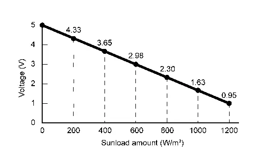
63
Is the inspection result normal?
YES>>Inspection End.
NO>>GO TO 2.
CHECK SUNLOAD SENSOR POWER SUPPLY
-
Ignition switch OFF.
-
Disconnect sunload sensor connector.
-
Ignition switch ON.
-
Check voltage between sunload sensor harness connector and ground.
+ − Voltage
(Approx.)Sunload sensor Connector Terminal M278 1 Ground 5 V 2
Is the inspection result normal?
YES>>GO TO 3.
NO>>GO TO 5.
CHECK SUNLOAD SENSOR GROUND CIRCUIT FOR OPEN
-
Ignition switch OFF.
-
Disconnect A/C auto amp. connector.
-
Check continuity between sunload sensor harness connector and A/C auto amp. harness connector.
Sunload sensor A/C auto amp. Continuity Connector Terminal Connector Terminal M278 3 M60 78 Yes
Is the inspection result normal?
YES>>GO TO 4.
NO>>Repair harness or connector.
REPLACE SUNLOAD SENSOR
Replace sunload sensor. Refer to Removal and Installation.
Is the inspection result normal?
YES>>Inspection End.
NO>>Replace A/C auto amp. Refer to Removal and Installation.
CHECK SUNLOAD SENSOR POWER SUPPLY CIRCUIT FOR OPEN
-
Ignition switch OFF.
-
Disconnect A/C auto amp. connector.
-
Check continuity between sunload sensor harness connector and A/C auto amp. harness connector.
Sunload sensor A/C auto amp. Continuity Connector Terminal Connector Terminal M278 1 M60 63 Yes 2 47
Is the inspection result normal?
YES>>GO TO 6.
NO>>Repair harness or connector.
CHECK SUNLOAD SENSOR POWER SUPPLY CIRCUIT FOR SHORT
Check continuity between sunload sensor harness connector and ground.
| Sunload sensor | — | Continuity | |
|---|---|---|---|
| Connector | Terminal | ||
| M278 | 1 | Ground | No |
| 2 | |||
Is the inspection result normal?
YES>>GO TO 4.
NO>>Repair harness or connector.
Door Motor Nissan Pathfinder SUV
Diagnosis Procedure
 NOTE:
NOTE:
If all of door motor DTCs are detected, check this circuit.
CHECK DOOR MOTOR POWER SUPPLY
-
Ignition switch ON.
-
Check voltage between intake door motor harness connector and A/C auto amp. harness connector.
| + | − |
Voltage (Approx.) | ||
|---|---|---|---|---|
| Intake door motor | A/C auto amp. | |||
| Connector | Terminal | Connector | Terminal | |
| M128 | 1 | M60 | 58 | Battery voltage |
Is the inspection result normal?
YES>>GO TO 2.
NO>>GO TO 6.
CHECK DOOR MOTOR GROUND CIRCUIT FOR OPEN
-
Ignition switch OFF.
-
Disconnect intake door motor connector and A/C auto amp. connector.
-
Check continuity between intake door motor harness connector and A/C auto amp. harness connector.
Intake door motor A/C auto amp. Continuity Connector Terminal Connector Terminal M128 2 M50 27 Yes
Is the inspection result normal?
YES>>GO TO 3.
NO>>Repair harness or connector.
CHECK DOOR MOTOR LIN SIGNAL
-
Connect intake door motor connector and A/C auto amp. connector.
-
Ignition switch ON.
-
Confirm output waveform between intake door motor harness connector and A/C auto amp. harness connector with oscilloscope.
+ − Output waveform Intake door motor A/C auto amp. Connector Terminal Connector Terminal M128 3 M60 58 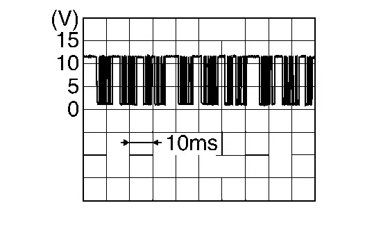
Is the inspection result normal?
YES>>Inspection End.
NO>>GO TO 4.
CHECK DOOR MOTOR LIN SIGNAL CIRCUIT FOR OPEN
-
Ignition switch OFF.
-
Disconnect A/C auto amp. and intake door motor connector.
-
Check continuity between intake door motor harness connector and A/C auto amp. harness connector.
Intake door motor A/C auto amp. Continuity Connector Terminal Connector Terminal M128 3 M50 2 Yes
Is the inspection result normal?
YES>>GO TO 5.
NO>>Repair harness or connector.
CHECK DOOR MOTOR LIN SIGNAL CIRCUIT FOR SHORT
-
Ignition switch OFF.
-
Disconnect following connectors:
-
Air mix door motor LH
-
Air mix door motor RH
-
Air mix door motor (rear)
-
Mode door motor (front)
-
Mode door motor (rear)
-
-
Check continuity between A/C auto amp. harness connector and ground.
A/C auto amp. — Continuity Connector Terminal M50 2 Ground No
Is the inspection result normal?
YES>>Replace A/C auto amp. Refer to Removal and Installation.
NO>>Repair harness or connector.
CHECK DOOR MOTOR POWER SUPPLY CIRCUIT FOR OPEN
-
Ignition switch OFF.
-
Disconnect intake door motor and A/C auto amp. connector.
-
Check continuity between intake door motor harness connector and A/C auto amp. harness connector.
Intake door motor A/C auto amp. Continuity Connector Terminal Connector Terminal M128 1 M50 1 Yes
Is the inspection result normal?
YES>>GO TO 7.
NO>>Repair harness or connector.
CHECK DOOR MOTOR POWER SUPPLY CIRCUIT FOR SHORT
-
Disconnect following connectors:
-
Air mix door motor LH
-
Air mix door motor RH
-
Air mix door motor (rear)
-
Mode door motor (front)
-
Mode door motor (rear)
-
-
Check continuity between A/C auto amp. harness connector and ground.
A/C auto amp. — Continuity Connector Terminal M50 1 Ground No
Is the inspection result normal?
YES>>Replace A/C auto amp. Refer to Removal and Installation.
NO>>Repair harness or connector.
Front Blower Motor Nissan Pathfinder
Diagnosis Procedure
CHECK FUSIBLE LINK
-
Ignition switch OFF.
-
Check that the following fusible link is not blown (open):
Unit Location Fusible link No. Capacity Front blower motor Fuse block (J/B) FF 40 A
Is the fusible link blown (open)?
YES>>Replace the blown fuse after repairing the affected circuit.
NO>>GO TO 2.
CHECK FRONT BLOWER MOTOR POWER SUPPLY
-
Disconnect the front blower motor connector.
-
Ignition switch ON.
-
Check voltage between front blower motor harness connector and ground.
+ − Voltage
(Approx.)Front blower motor Connector Terminal M187 1 Ground Battery voltage
Is the inspection result normal?
YES>>GO TO 4.
NO>>GO TO 3.
CHECK FRONT BLOWER MOTOR POWER SUPPLY CIRCUIT FOR OPEN
-
Ignition switch OFF.
-
Disconnect fuse block (J/B) harness connector.
-
Check continuity between fuse block (J/B) harness connector and front blower motor harness connector.
Fuse block (J/B) Front blower motor Continuity Connector Terminal Connector Terminal M3 1A M187 1 Yes
Is the inspection result normal?
YES>>Repair the front blower motor power supply circuit.
NO>>Repair the harnesses or connectors.
CHECK FRONT BLOWER MOTOR GROUND CIRCUIT FOR OPEN
-
Ignition switch OFF.
-
Check continuity between front blower motor harness connector and ground.
Front blower motor — Continuity Connector Terminal M187 3 Ground Yes
Is the inspection result normal?
YES>>GO TO 5.
NO>>Repair the harnesses or connectors.
CHECK FRONT BLOWER MOTOR CONTROL SIGNAL
-
Connect front blower motor connector.
-
Ignition switch ON.
-
Check duty ratios between front blower motor harness connector and ground by using an oscilloscope.
+ − Condition Output waveform
(Approx.)Front blower motor Connector Terminal M187 2 Ground Front blower motor: OFF Battery voltage Front blower motor: 1st speed (manual) 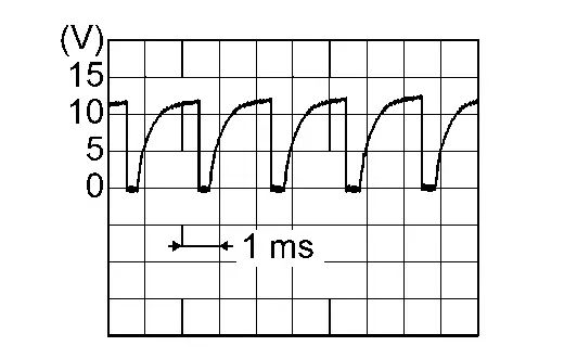
Front blower motor: 7th speed (manual) 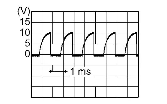
Is the inspection result normal?
YES>>Replace front blower motor. Refer to Removal and Installation.
NO>>GO TO 6.
CHECK FRONT BLOWER MOTOR CONTROL SIGNAL CIRCUIT FOR OPEN
-
Ignition switch OFF.
-
Disconnect front blower motor connector and A/C auto amp. connector.
-
Check continuity between front blower motor harness connector and A/C auto amp. harness connector.
Front blower motor A/C auto amp. Continuity Connector Terminal Connector Terminal M187 2 M50 34 Yes
Is the inspection result normal?
YES>>GO TO 7.
NO>>Repair the harnesses or connectors.
REPLACE FRONT BLOWER MOTOR
-
Replace front blower motor. Refer to Removal and Installation.
-
Ignition switch ON.
-
Change fan speed from 1st – 7th, and check that front blower motor operates normally.
Is the inspection result normal?
YES>>Inspection End.
NO>>Replace the A/C auto amp. Refer to Removal and Installation.
Component Inspection (Front Blower Motor)
CHECK FRONT BLOWER MOTOR-I
-
Replace front blower motor. Refer to Removal and Installation.
-
Check that there is not any mixing foreign object in the front blower motor.
Is the inspection result normal?
YES>>GO TO 2.
NO>>Replace front blower motor. Refer to Removal and Installation.
CHECK FRONT BLOWER MOTOR-II
Check that there is not breakage or damage in the front blower motor.
Is the inspection result normal?
YES>>GO TO 3.
NO>>Replace front blower motor. Refer to Removal and Installation.
CHECK FRONT BLOWER MOTOR-III
Check that front blower motor turns smoothly.
Is the inspection result normal?
YES>>Inspection End.
NO>>Replace front blower motor. Refer to Removal and Installation.
Rear Blower Motor Nissan Pathfinder 2022
Diagnosis Procedure
CHECK REAR BLOWER MOTOR POWER SUPPLY
-
Disconnect the rear blower motor connector.
-
Ignition switch ON.
-
Check voltage between rear blower motor harness connector and ground.
+ − Voltage
(Approx.)Rear blower motor Connector Terminal B126 1 Ground Battery voltage
Is the inspection result normal?
YES>>GO TO 3.
NO>>GO TO 2.
CHECK REAR BLOWER MOTOR POWER SUPPLY CIRCUIT FOR OPEN
-
Ignition switch OFF.
-
Disconnect rear blower motor resistor connector.
-
Check continuity between rear blower motor resistor harness connector and rear blower motor harness connector.
Rear blower motor resistor Rear blower motor Continuity Connector Terminal Connector Terminal B134 1 B126 1 Yes
Is the inspection result normal?
YES>>Repair the rear blower motor power supply circuit.
NO>>Repair the harnesses or connectors.
CHECK REAR BLOWER MOTOR GROUND CIRCUIT FOR OPEN
-
Ignition switch OFF.
-
Check continuity between rear blower motor harness connector and ground.
Rear blower motor — Continuity Connector Terminal B126 2 Ground Yes
Is the inspection result normal?
YES>>GO TO 4.
NO>>Repair the harnesses or connectors.
REPLACE REAR BLOWER MOTOR
-
Replace rear blower motor. Refer to Removal and Installation.
-
Ignition switch ON.
-
Change fan speed from 1st – 7th, and check that rear blower motor operates normally.
Is the inspection result normal?
YES>>Inspection End.
NO>>Replace the rear blower motor resistor. Refer to Removal and Installation.
Component Inspection (Rear Blower Motor)
CHECK REAR BLOWER MOTOR-I
-
Replace rear blower motor. Refer to Removal and Installation.
-
Check that there is not any mixing foreign object in the rear blower motor.
Is the inspection result normal?
YES>>GO TO 2.
NO>>Replace rear blower motor. Refer to Removal and Installation.
CHECK REAR BLOWER MOTOR-II
Check that there is not breakage or damage in the rear blower motor.
Is the inspection result normal?
YES>>GO TO 3.
NO>>Replace rear blower motor. Refer to Removal and Installation.
CHECK REAR BLOWER MOTOR-III
Check that rear blower motor turns smoothly.
Is the inspection result normal?
YES>>Inspection End.
NO>>Replace rear blower motor. Refer to Removal and Installation.
Magnetic Clutch Nissan Pathfinder 2026
Component Function Check
CHECK MAGNETIC CLUTCH OPERATION
 CONSULT
-
Select “HVAC TEST” in “Active Test” mode of “HVAC”.
-
Select “MODE 1”.
-
With operating the test item, check magnetic clutch operation by listening and viewing.
Does it operate normally?
YES>>Inspection End.
NO>>Refer to Diagnosis Procedure.
Diagnosis Procedure
CHECK MAGNETIC CLUTCH
 CONSULT
-
Ignition switch ON.
-
Select “HVAC TEST” in “Active Test” mode of “HVAC”.
-
With operating the test item, check voltage between IPDM E/R harness connector and ground.
+ − Condition Voltage
(Approx.)IPDM E/R Connector Terminal F24 65 Ground Active test: HVAC TEST Off 0 V MODE 1 Battery voltage
Is the inspection result normal?
YES>>GO TO 2.
NO>>Replace IPDM E/R. Refer to Removal and Installation.
CHECK MAGNETIC CLUTCH POWER SUPPLY CIRCUIT FOR OPEN
-
Ignition switch OFF.
-
Disconnect IPDM E/R connector and A/C compressor connector.
-
Check continuity between IPDM E/R harness connector and A/C compressor harness connector.
IPDM E/R A/C compressor Continuity Connector Terminal Connector Terminal F24 65 F3 1 Yes
Is the inspection result normal?
YES>>GO TO 3.
NO>>Repair harness or connector.
CHECK MAGNETIC CLUTCH GROUND CIRCUIT FOR OPEN
Check continuity between A/C compressor harness connector and ground.
| A/C compressor | — | Continuity | |
|---|---|---|---|
| Connector | Terminal | ||
| F3 | 2 | Ground | Yes |
Is the inspection result normal?
YES>>Replace A/C compressor. Refer to Removal and Installation.
NO>>Repair harness or connector.
Ecv (electrical Control Valve) Nissan Pathfinder 2022
Diagnosis Procedure
CHECK FUSE
-
Ignition switch OFF.
-
Check that the following fuse is not blown (open):
Unit Location Fuse No. Capacity A/C compressor IPDM E/R 71 10 A
Is the fuse blown (open)?
YES>>Replace the blown fuse after repairing the affected circuit.
NO>>GO TO 2.
CHECK ECV POWER SUPPLY CIRCUIT
-
Disconnect A/C compressor connector.
-
Ignition switch ON.
-
Check voltage between A/C compressor harness connector and ground.
+ − Voltage
(Approx.)A/C compressor Connector Terminal F4 3 Ground Battery voltage
Is the inspection result normal?
YES>>GO TO 4.
NO>>GO TO 3.
CHECK ECV POWER SUPPLY CIRCUIT FOR OPEN
-
Ignition switch OFF.
-
Disconnect IPDM E/R connector.
-
Check continuity between A/C compressor harness connector and IPDM E/R harness connector.
A/C compressor IPDM E/R Continuity Connector Terminal Connector Terminal F4 3 F24 71 Yes
Is the inspection result normal?
YES>>Replace IPDM E/R. Refer to Removal and Installation.
NO>>Repair harness or connector.
CHECK ECV CONTROL SIGNAL CIRCUIT FOR OPEN
-
Ignition switch OFF.
-
Disconnect IPDM E/R connector.
-
Check continuity between A/C compressor harness connector and IPDM E/R harness connector.
A/C compressor IPDM E/R Continuity Connector Terminal Connector Terminal F4 4 E78 98 Yes
Is the inspection result normal?
YES>>GO TO 5.
NO>>Repair harness or connector.
CHECK ECV
Check ECV. Refer to Component Inspection.
Is the inspection result normal?
YES>>Replace IPDM E/R. Refer to Removal and Installation.
NO>>Replace A/C compressor. Refer to Removal and Installation.
Component Inspection
CHECK ECV
-
Ignition switch OFF.
-
Check continuity between A/C compressor terminals.
| A/C compressor | Continuity | |
|---|---|---|
| Terminals | ||
| 3 | 4 | Yes |
Is the inspection result normal?
YES>>Inspection End.
NO>>Replace A/C compressor. Refer to Removal and Installation.
Rear Blower Motor Resistor Nissan Pathfinder R53
Diagnosis Procedure
CHECK REAR BLOWER MOTOR RESISTOR POWER SUPPLY CIRCUIT
-
Ignition switch OFF.
-
Disconnect rear blower motor resistor connector.
-
Ignition switch ON.
-
Check voltage between rear blower motor resistor harness connector and ground.
+ — Voltage
(Approx.)Rear blower motor resistor Connector Terminal B133 6 Ground Battery voltage
Is the inspection result normal?
YES>>GO TO 2.
NO>>GO TO 5.
CHECK REAR BLOWER MOTOR RESISTOR GROUND CIRCUIT
-
Ignition switch OFF.
-
Check continuity between rear blower motor resistor harness connector and ground.
Rear blower motor resistor — Continuity Connector Terminal B133 4 Ground Yes
Is the inspection result normal?
YES>>GO TO 3.
NO>>Repair harness or connector.
CHECK REAR BLOWER MOTOR RESISTOR SIGNAL CIRCUIT FOR OPEN
-
Disconnect A/C auto amp. connector.
-
Check continuity between rear blower motor resistor harness connector and A/C auto amp. harness connector.
Rear blower motor resistor A/C auto amp. Continuity Connector Terminal Connector Terminal B133 5 M60 74 Yes
Is the inspection result normal?
YES>>GO TO 4.
NO>>Repair harness or connector.
CHECK REAR BLOWER MOTOR RESISTOR SIGNAL CIRCUIT FOR SHORT
Check continuity between rear blower motor resistor harness connector and ground.
| Rear blower motor resistor | — | Continuity | |
|---|---|---|---|
| Connector | Terminal | ||
| B133 | 5 | Ground | No |
Is the inspection result normal?
YES>>Replace rear blower motor resistor. Refer to Removal and Installation.
NO>>Repair harness or connector.
CHECK REAR BLOWER MOTOR RESISTOR POWER SUPPLY CIRCUIT FOR OPEN
-
Ignition switch OFF.
-
Disconnect fuse block(J/B) connector.
-
Check continuity between rear blower motor resistor harness connector and fuse block(J/B) harness connector.
Rear blower motor resistor Fuse block(J/B) Continuity Connector Terminal Connector Terminal B133 6 B34 7M No
Is the inspection result normal?
YES>>Check the 20A fuse [No. 64, located in fuse block (J/B)].
NO>>Repair harness or connector.

Nissan Pathfinder (R53) 2022-2026 Service Manual
Dtc/circuit Diagnosis
- Power Supply and Ground Circuit
- Sunload Sensor
- Door Motor
- Front Blower Motor
- Rear Blower Motor
- Magnetic Clutch
- Ecv (electrical Control Valve)
- Rear Blower Motor Resistor
- B20c7-11 A/c Clutch
- B20c7-15 A/c Clutch
- B2480-93 Rear Air Mix Door Motor
- B24a0-49 A/c Auto Amp.
- B24a1-16 A/c Amp. Power Supply
- B24a2-55 Configuration Not Implement
- B24a4-11 Intake Sensor
- B24a4-15 Intake Sensor
- B24a6-11 in-Vehicle Sensor
- B24a6-15 in-Vehicle Sensor
- B24b4-02 A/c Control Comm
- B24c6-12 Blower Motor Control
- B24f5-93 Mode Door Motor
- U1ca1-08 A/c Switch Assembly Communication
- U1ca2-08 Door Motor Communication
- U1caa-02 Mode Door Motor
- U2140-87 Can Comm Err (ecm)
Contact Us
Nissan Pathfinder Info Center
Email: info@nipathfinder.com
Phone: +1 (800) 123-4567
Address: 123 Pathfinder Blvd, Nashville, TN 37214, USA
Working Hours: Mon–Fri, 9:00 AM – 5:00 PM (EST)
