Nissan Pathfinder: Dtc/circuit Diagnosis (B24a6-15 in-Vehicle Sensor ... U2140-87 Can Comm Err (ecm))
- B24a6-15 in-Vehicle Sensor
- B24b4-02 A/c Control Comm
- B24c6-12 Blower Motor Control
- B24f5-93 Mode Door Motor
- U1ca1-08 A/c Switch Assembly Communication
- U1ca2-08 Door Motor Communication
- U1caa-02 Mode Door Motor
- U2140-87 Can Comm Err (ecm)
B24a6-15 in-Vehicle Sensor Nissan Pathfinder 2022
DTC Description
DTC DETECTION LOGIC
| DTC No. |
CONSULT screen terms (Trouble diagnosis content) | DTC detection condition | |
|---|---|---|---|
| B24A6-15 |
IN-Nissan Pathfinder Vehicle SENSOR (In-vehicle sensor) |
Diagnosis condition | Ignition switch ON |
| Signal (Terminal) | In-Nissan Pathfinder vehicle sensor signal | ||
| Threshold | The in-Nissan Pathfinder vehicle sensor recognition temperature is too low [less than -44°F (-42°C)] | ||
| Diagnosis delay time | 2 second or more | ||
POSSIBLE CAUSE
-
Front in-vehicle sensor
-
A/C auto amp.
-
Harness or connectors (the sensor circuit is open or shorted to battery)
FAIL-SAFE
In-vehicle temperature is calculated as 77°F (25°C) and air conditioning system is controlled.
DTC CONFIRMATION PROCEDURE
PERFORM DTC CONFIRMATION PROCEDURE
 CONSULT
-
Ignition switch ON.
-
Select “Self Diagnostic Result” mode of “HVAC”.
-
Check DTC.
Is DTC detected?
YES>>Refer to DTC Diagnosis Procedure.
NO>>To check malfunction symptom before repair: Refer to Intermittent Incident.
NO>>Confirmation after repair: Inspection End.
DTC Diagnosis Procedure
CHECK FRONT IN-VEHICLE SENSOR SIGNAL
-
Ignition switch ON.
-
Check voltage between A/C auto amp. harness connector.
A/C auto amp. Voltage
(Approx.)Connector Terminals + - M60 48 78 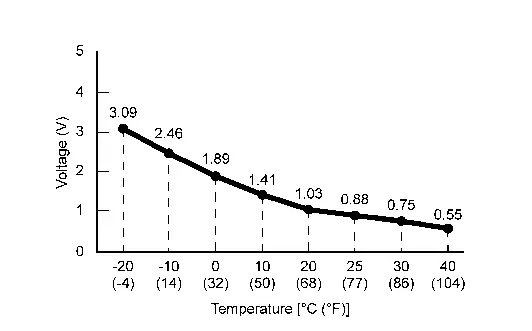
Is the inspection result normal?
YES>>Replace A/C auto amp. Refer to Removal and Installation.
NO>>GO TO 2.
CHECK FRONT IN-Nissan Pathfinder Vehicle SENSOR POWER SUPPLY
-
Ignition switch OFF.
-
Disconnect front in-vehicle sensor connector.
-
Ignition switch ON.
-
Check voltage between front in-Nissan Pathfinder vehicle sensor harness connector and ground.
+ - Voltage
(Approx.)Front in-Nissan Pathfinder vehicle sensor Connector Terminal M102 1 Ground 5 V
Is the inspection result normal?
YES>>GO TO 3.
NO>>GO TO 5.
CHECK FRONT IN-Nissan Pathfinder Vehicle SENSOR GROUND CIRCUIT FOR OPEN
-
Ignition switch OFF.
-
Disconnect A/C auto amp. connector.
-
Check continuity between front in-Nissan Pathfinder vehicle sensor harness connector and A/C auto amp. harness connector.
Front in-Nissan Pathfinder vehicle sensor A/C auto amp. Continuity Connector Terminal Connector Terminal M102 2 M60 78 Yes
Is the inspection result normal?
YES>>GO TO 4.
NO>>Repair harness or connector.
CHECK FRONT IN-Nissan Pathfinder Vehicle SENSOR
Check front in-vehicle sensor. Refer to Component Inspection.
Is the inspection result normal?
YES>>Replace A/C auto amp. Refer to Removal and Installation.
NO>>Replace front in-Nissan Pathfinder vehicle sensor. Refer to Removal and Installation.
CHECK FRONT IN-Nissan Pathfinder Vehicle SENSOR POWER SUPPLY CIRCUIT FOR OPEN
-
Ignition switch OFF.
-
Disconnect A/C auto amp. connector.
-
Check continuity between front in-Nissan Pathfinder vehicle sensor harness connector and A/C auto amp. harness connector.
Front in-Nissan Pathfinder vehicle sensor A/C auto amp. Continuity Connector Terminal Connector Terminal M102 1 M60 48 Yes
Is the inspection result normal?
YES>>GO TO 6.
NO>>Repair harness or connector.
CHECK FRONT IN-Nissan Pathfinder Vehicle SENSOR POWER SUPPLY CIRCUIT FOR SHORT
Check voltage between front in-vehicle sensor harness connector and ground.
| + | - |
Voltage (Approx.) | |
|---|---|---|---|
| Front in-Nissan Pathfinder vehicle sensor | |||
| Connector | Terminal | ||
| M102 | 1 | Ground | 0 V |
Is the inspection result normal?
YES>>Replace A/C auto amp. Refer to Removal and Installation.
NO>>Repair harness or connector.
Component Inspection
CHECK FRONT IN-VEHICLE SENSOR
-
Ignition switch OFF.
-
Remove front in-Nissan Pathfinder vehicle sensor. Refer to Removal and Installation.
-
Check resistance between front in-vehicle sensor terminals. Refer to applicable table for the normal value.
Front in-Nissan Pathfinder vehicle sensor Condition Resistance: kΩ Terminals Temperature: °F (°C) 1 2 −4 (−20) 16.50 14 (−10) 9.92 32 (0) 6.19 50 (10) 3.99 68 (20) 2.65 77 (25) 2.19 86 (30) 1.81 104 (40) 1.27
Is the inspection result normal?
YES>>Inspection End.
NO>>Replace front in-Nissan Pathfinder vehicle sensor. Refer to Removal and Installation.
B24b4-02 A/c Control Comm Nissan Pathfinder 2022
DTC Description
DTC DETECTION LOGIC
| DTC No. |
CONSULT screen terms (Trouble diagnosis content) | DTC detection condition | |
|---|---|---|---|
| B24B4-02 |
A/C CONTROL COMM (Air conditioning control communication) |
Diagnosis condition | Ignition switch ON |
| Signal (Terminal) | LIN (A/C switch assembly) signal | ||
| Threshold | Receive internal circuit error message via front A/C switch assembly to LIN communication | ||
| Diagnosis delay time | 30 second or more | ||
POSSIBLE CAUSE
Front A/C switch assembly (internal circuit malfunction)
FAIL-SAFE
—
DTC CONFIRMATION PROCEDURE
PERFORM SELF-DIAGNOSIS
 CONSULT
-
Ignition switch ON.
-
Select “Self Diagnostic Result” mode of “HVAC”.
-
Check DTC.
Is DTC detected?
YES>>Refer to DTC Diagnosis Procedure.
NO>>To check malfunction symptom before repair: Refer to Intermittent Incident.
NO>>Confirmation after repair: Inspection End.
DTC Diagnosis Procedure
PERFORM SELF DIAGNOSTIC RESULT
 CONSULT
-
Ignition switch ON.
-
Select “Self Diagnostic Result” mode of “HVAC”.
-
Select “ERASE”.
-
Ignition switch OFF.
-
Ignition switch ON.
-
Perform “DTC CONFIRMATION PROCEDURE”. Refer to DTC Description.
Is DTC detected again?
YES>>Replace front A/C switch assembly. Refer to Removal and Installation.
NO>>Inspection End.
B24c6-12 Blower Motor Control Nissan Pathfinder 2022
DTC Description
DTC DETECTION LOGIC
| DTC No. |
CONSULT screen terms (Trouble diagnosis content) | DTC detection condition | ||
|---|---|---|---|---|
| B24C6-12 |
BLOWER MOTOR CONTROL (Blower motor control) |
[CIRCUIT SHORT TO GROUND] | Diagnosis condition | When ignition switch is ON |
| Signal (Terminal) | Blower motor control signal | |||
| Threshold | Blower motor control signal circuit has a short to ground | |||
| Diagnosis delay time | — | |||
POSSIBLE CAUSE
-
Harness or connectors (blower motor control signal circuit is shorted to ground)
-
A/C auto amp.
FAIL-SAFE
—
DTC CONFIRMATION PROCEDURE
PERFORM SELF DIAGNOSTIC RESULT
 CONSULT
-
Ignition switch ON.
-
Select “Self Diagnostic Result” mode of “HVAC”.
-
Check DTC.
Is DTC detected?
YES>>Refer to DTC Diagnosis Procedure.
NO>>To check malfunction symptom before repair: Refer to Intermittent Incident.
NO>>Confirmation after repair: Inspection End.
DTC Diagnosis Procedure
CHECK FRONT BLOWER MOTOR CONTROL SIGNAL
-
Ignition switch ON.
-
Check duty ratios between front blower motor harness connector and ground by using an oscilloscope.
(+) (–) Condition Output waveform
(Approx.)Front blower motor Connector Terminal M187 2 Ground Front blower motor: OFF Battery voltage Front blower motor: 1st speed (manual) 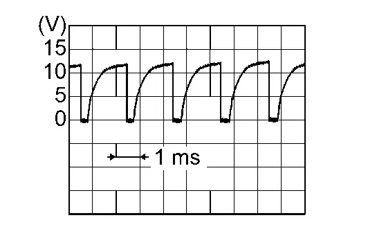
Front blower motor: 7th speed (manual) 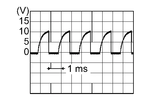
Is the inspection result normal?
YES>>Replace front blower motor. Refer to Removal and Installation.
NO>>GO TO 2.
CHECK FRONT BLOWER MOTOR CONTROL SIGNAL CIRCUIT FOR OPEN
-
Ignition switch OFF.
-
Disconnect front blower motor connector and A/C auto amp. connector.
-
Check continuity between front blower motor harness connector and A/C auto amp. harness connector.
Front blower motor A/C auto amp. Continuity Connector Terminal Connector Terminal M187 2 M50 34 Yes -
Check continuity between front blower motor harness connector and ground.
Front blower motor (–) Continuity Connector Terminal M187 2 Ground No
Is the inspection result normal?
YES>>Replace the A/C auto amp. Refer to Removal and Installation.
NO>>Repair the harnesses or connectors.
B24f5-93 Mode Door Motor Nissan Pathfinder
DTC Description
DTC DETECTION LOGIC
 NOTE:
NOTE:
If all of door motors DTC (B2480-93, B24F5-93, B24F6-93, B24F7-93, B24F8-93) are detected, check “DOOR MOTOR CIRCUIT”. Refer to Diagnosis Procedure.
| DTC No. |
CONSULT screen terms (Trouble diagnosis content) | DTC detection condition | |
|---|---|---|---|
| B24F5-93 |
Mode door motor (Mode door motor) |
Diagnosis condition | Ignition switch ON |
| Signal (Terminal) | LIN (door motor) signal | ||
| Threshold | Drive error of mode door motor (front) is detected | ||
| Diagnosis delay time | 2 second or more | ||
POSSIBLE CAUSE
-
Harness and connector [mode door motor (front) circuit is open or shorted to ground]
-
Mode door motor (front) installation condition
-
Mode door motor (front)
-
A/C auto amp.
FAIL-SAFE
—
DTC CONFIRMATION PROCEDURE
PERFORM DTC CONFIRMATION PROCEDURE
 CONSULT
-
Start the engine.
-
Select “Self Diagnostic Result” mode of “HVAC”.
-
Check DTC.
Is DTC detected?
YES>>Refer to DTC Diagnosis Procedure.
NO>>To check malfunction symptom before repair: Refer to Intermittent Incident.
NO>>Confirmation after repair: Inspection End.
DTC Diagnosis Procedure
CHECK MODE DOOR MOTOR (FRONT) POWER SUPPLY
-
Ignition switch ON.
-
Check voltage between mode door motor (front) harness connector and ground.
| + | − |
Voltage (Approx.) | |
|---|---|---|---|
| Mode door motor (front) | |||
| Connector | Terminal | ||
| M129 | 1 | Ground | Battery voltage |
Is the inspection result normal?
YES>>GO TO 2.
NO>>GO TO 5.
CHECK MODE DOOR MOTOR (FRONT) GROUND CIRCUIT FOR OPEN
-
Ignition switch OFF.
-
Disconnect mode door motor (front) connector and A/C auto amp. connector.
-
Check continuity between mode door motor (front) harness connector and A/C auto amp. harness connector.
Mode door motor (front) A/C auto amp. Continuity Connector Terminal Connector Terminal M129 2 M50 27 Yes
Is the inspection result normal?
YES>>GO TO 3.
NO>>Repair harness or connector.
CHECK MODE DOOR MOTOR (FRONT) LIN SIGNAL CIRCUIT
-
Connect mode door motor (front) connector and A/C auto amp. connector.
-
Ignition switch ON.
-
Confirm output waveform between mode door motor (front) harness connector and ground with oscilloscope.
+ − Output waveform Mode door motor Connector Terminal M129 3 Ground 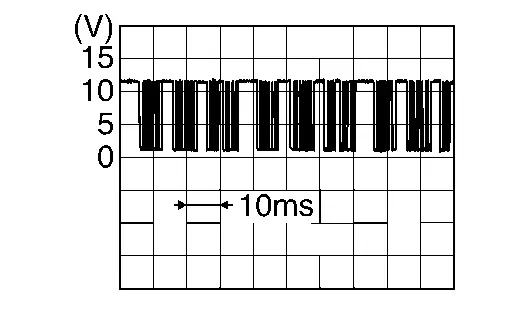
Is the inspection result normal?
YES>>GO TO 4.
NO>>GO TO 6.
CHECK INSTALLATION OF MODE DOOR MOTOR (FRONT)
Check mode door motor (front) is properly installed. Refer to Exploded View.
Is the inspection result normal?
YES>>Replace mode door motor (front). Refer to Removal and Installation - Mode Door Motor (Front).
NO>>Repair or replace malfunctioning part.
CHECK MODE DOOR MOTOR (FRONT) POWER SUPPLY CIRCUIT FOR OPEN
-
Ignition switch OFF.
-
Disconnect mode door motor (front) connector and A/C auto amp. connector.
-
Check continuity between mode door motor (front) harness connector and A/C auto amp. harness connector.
Mode door motor (front) A/C auto amp. Continuity Connector Terminal Connector Terminal M129 1 M50 1 Yes
Is the inspection result normal?
YES>>Replace A/C auto amp. Refer to Removal and Installation.
NO>>Repair harness or connector.
CHECK MODE DOOR MOTOR (FRONT) LIN SIGNAL CIRCUIT FOR OPEN
-
Ignition switch OFF.
-
Disconnect mode door motor (front) connector and A/C auto amp. connector.
-
Check continuity between mode door motor (front) harness connector and A/C auto amp. harness connector.
Mode door motor (front) A/C auto amp. Continuity Connector Terminal Connector Terminal M129 3 M50 2 Yes
Is the inspection result normal?
YES>>Replace A/C auto amp. Refer to Removal and Installation.
NO>>Repair harness or connector.
U1ca1-08 A/c Switch Assembly Communication Nissan Pathfinder SUV
DTC Description
DTC DETECTION LOGIC
| DTC No. |
CONSULT screen terms (Trouble diagnosis content) | DTC detection condition | |
|---|---|---|---|
| U1CA1-08 |
LIN communication 2 (Local interconnect network communication 2) |
Diagnosis condition | Ignition switch ON |
| Signal (Terminal) | LIN (A/C control) signal | ||
| Threshold | A/C auto amp. is not transmitting or receiving LIN communication with front A/C switch assembly or rear A/C switch assembly | ||
| Diagnosis delay time | 2 second or more | ||
POSSIBLE CAUSE
-
Front A/C switch assembly
-
Rear A/C switch assembly
-
A/C auto amp.
FAIL-SAFE
—
DTC CONFIRMATION PROCEDURE
PERFORM DTC CONFIRMATION PROCEDURE
 CONSULT
-
Ignition switch ON.
-
Select “Self Diagnostic Result” mode of “HVAC”.
-
Check DTC.
Is DTC detected?
YES>>Refer to DTC Diagnosis Procedure.
NO>>To check malfunction symptom before repair: Refer to Intermittent Incident.
NO>>Confirmation after repair: Inspection End.
DTC Diagnosis Procedure
CHECK DTC
 CONSULT
-
Ignition switch ON.
-
Select “Self Diagnostic Result” mode of “HVAC”.
-
Check following DTC:
DTC Items
(CONSULT screen terms)Reference B24B4-02 A/C CONTROL COMM DTC Description U1CB1-02 A/C control 2 communication DTC Description
Is DTC detected?
YES>>Perform DTC diagnosis procedure that is detecting.
NO>>Replace A/C auto amp. Refer to Removal and Installation.
U1ca2-08 Door Motor Communication Nissan Pathfinder R53
DTC Description
DTC DETECTION LOGIC
| DTC No. |
CONSULT screen terms (Trouble diagnosis content) | DTC detection condition | |
|---|---|---|---|
| U1CA2-08 |
LIN communication 3 (Local interconnect network communication 3) |
Diagnosis condition | Ignition switch ON |
| Signal (Terminal) | LIN (door motor) signal | ||
| Threshold | A/C auto amp. is not transmitting or receiving LIN communication with each door motor | ||
| Diagnosis delay time | 2 second or more | ||
POSSIBLE CAUSE
-
Harness and connector (door motor circuit is open or shorted to ground)
-
Each door motor
-
A/C auto amp.
FAIL-SAFE
—
DTC CONFIRMATION PROCEDURE
PERFORM DTC CONFIRMATION PROCEDURE
 CONSULT
-
Start the engine.
-
Select “Self Diagnostic Result” mode of “HVAC”.
-
Check DTC.
Is DTC detected?
YES>>Refer to DTC Diagnosis Procedure.
NO>>To check malfunction symptom before repair: Refer to Intermittent Incident.
NO>>Confirmation after repair: Inspection End.
DTC Diagnosis Procedure
CHECK DTC
 CONSULT
-
Start the engine.
-
Select “Self Diagnostic Result” mode of “HVAC”.
-
Check following DTC:
DTC Items
(CONSULT screen terms)Reference U1CAA-02 Mode door motor DTC Description U1CAB-02 Intake door motor DTC Description U1CAC-02 Air mix door motor 1 DTC Description U1CAD-02 Air mix door motor 2 DTC Description U1CAE-02 Rear air mix door motor DTC Description
Is DTC detected?
YES>>Perform DTC diagnosis procedure that is detecting.
NO>>Replace A/C auto amp. Refer to Removal and Installation.
U1caa-02 Mode Door Motor Nissan Pathfinder R53
DTC Description
DTC DETECTION LOGIC
| DTC No. |
CONSULT screen terms (Trouble diagnosis content) | DTC detection condition | |
|---|---|---|---|
| U1CAA-02 |
Mode door motor (Mode door motor) |
Diagnosis condition | Ignition switch ON |
| Signal (Terminal) | LIN (door motor) signal | ||
| Threshold | A/C auto amp. is not transmitting or receiving LIN communication with mode door motor (front) | ||
| Diagnosis delay time | 2 second or more | ||
POSSIBLE CAUSE
-
Harness and connector [mode door motor (front) circuit is open or shorted to ground]
-
Mode door motor (front)
-
A/C auto amp.
FAIL-SAFE
—
DTC CONFIRMATION PROCEDURE
PERFORM DTC CONFIRMATION PROCEDURE
 CONSULT
-
Start the engine.
-
Select “Self Diagnostic Result” mode of “HVAC”.
-
Check DTC.
Is DTC detected?
YES>>Refer to DTC Diagnosis Procedure.
NO>>To check malfunction symptom before repair: Refer to Intermittent Incident.
NO>>Confirmation after repair: Inspection End.
DTC Diagnosis Procedure
CHECK MODE DOOR MOTOR (FRONT) POWER SUPPLY
-
Ignition switch ON.
-
Check voltage between mode door motor (front) harness connector and ground.
| + | − |
Voltage (Approx.) | |
|---|---|---|---|
| Mode door motor (front) | |||
| Connector | Terminal | ||
| M129 | 1 | Ground | Battery voltage |
Is the inspection result normal?
YES>>GO TO 2.
NO>>GO TO 4.
CHECK MODE DOOR MOTOR (FRONT) GROUND CIRCUIT FOR OPEN
-
Ignition switch OFF.
-
Disconnect mode door motor (front) connector and A/C auto amp. connector.
-
Check continuity between mode door motor (front) harness connector and A/C auto amp. harness connector.
Mode door motor (front) A/C auto amp. Continuity Connector Terminal Connector Terminal M129 2 M50 27 Yes
Is the inspection result normal?
YES>>GO TO 3.
NO>>Repair harness or connector.
CHECK MODE DOOR MOTOR (FRONT) LIN SIGNAL CIRCUIT
-
Connect mode door motor (front) connector and A/C auto amp. connector.
-
Ignition switch ON.
-
Confirm output waveform between mode door motor (front) harness connector and ground with oscilloscope.
+ − Output waveform Mode door motor (front) Connector Terminal M129 3 Ground 
Is the inspection result normal?
YES>>Replace mode door motor (front). Refer to Removal and Installation - Mode Door Motor (Front).
NO>>GO TO 6.
CHECK MODE DOOR MOTOR (FRONT) POWER SUPPLY CIRCUIT FOR OPEN
-
Ignition switch OFF.
-
Disconnect mode door motor (front) connector and A/C auto amp. connector.
-
Check continuity between mode door motor (front) harness connector and A/C auto amp. harness connector.
Mode door motor (front) A/C auto amp. Continuity Connector Terminal Connector Terminal M129 1 M50 1 Yes
Is the inspection result normal?
YES>>GO TO 5.
NO>>Repair harness or connector.
CHECK MODE DOOR MOTOR (FRONT) POWER SUPPLY CIRCUIT FOR SHORT
-
Disconnect following connectors:
-
Air mix door motor LH
-
Air mix door motor RH
-
Air mix door motor (rear)
-
Intake door motor
-
Mode door motor (rear)
-
-
Check continuity between mode door motor harness connector and ground.
Mode door motor (front) — Continuity Connector Terminal M129 1 Ground No
Is the inspection result normal?
YES>>Replace A/C auto amp. Refer to Removal and Installation.
NO>>Repair harness or connector.
CHECK MODE DOOR MOTOR (FRONT) LIN SIGNAL CIRCUIT FOR OPEN
-
Ignition switch OFF.
-
Disconnect mode door motor (front) connector and A/C auto amp. connector.
-
Check continuity between mode door motor (front) harness connector and A/C auto amp. harness connector.
Mode door motor (front) A/C auto amp. Continuity Connector Terminal Connector Terminal M129 3 M50 2 Yes
Is the inspection result normal?
YES>>GO TO 7.
NO>>Repair harness or connector.
CHECK MODE DOOR MOTOR (FRONT) LIN SIGNAL CIRCUIT FOR SHORT
-
Disconnect following connectors:
-
Air mix door motor LH
-
Air mix door motor RH
-
Air mix door motor (rear)
-
Intake door motor
-
Mode door motor (rear)
-
-
Check continuity between mode door motor (front) harness connector and ground.
Mode door motor (front) — Continuity Connector Terminal M129 3 Ground No
Is the inspection result normal?
YES>>Replace A/C auto amp. Refer to Removal and Installation.
NO>>Repair harness or connector.
U2140-87 Can Comm Err (ecm) Nissan Pathfinder 2022
DTC Description
DESCRIPTION
CAN (Controller Area Network) is a serial communication line for real time applications. It is an on-Nissan Pathfinder vehicle multiplex communication line with high data communication speed and excellent error detection ability. Modern Nissan Pathfinder vehicle is equipped with many electronic control unit, and each control unit shares information and links with other control units during operation (not independent). In CAN communication, control units are connected with 2 communication lines (CAN-High line, CAN-Low line) allowing a high rate of information transmission with less wiring. Each control unit transmits/receives data but selectively reads required data only. CAN Communication Signal Chart. Refer to CAN Communication Signal Chart.
DTC DETECTION LOGIC
| DTC No. |
CONSULT screen items (Trouble diagnosis content) | DTC Detection Condition | |
|---|---|---|---|
| U2140–87 |
CAN comm err (ECM) [CAN communication error (ECM)] |
Diagnosis condition | Ignition switch ON |
| Signal (terminal) | CAN communication signal | ||
| Threshold | A/C auto amp. is not transmitting or receiving CAN communication signal | ||
| Diagnosis delay time | 2 seconds or more | ||
POSSIBLE CAUSE
CAN communication system
FAIL-SAFE
—
DTC CONFIRMATION PROCEDURE
PERFORM SELF-DIAGNOSIS
 CONSULT
-
Ignition switch ON.
-
Select “Self Diagnostic Result” mode of “HVAC”.
-
Check DTC.
Is DTC detected?
YES>>Refer to DTC Diagnosis Procedure.
NO>>To check malfunction symptom before repair: Refer to Intermittent Incident.
NO>>Confirmation after repair: Inspection End.
DTC Diagnosis Procedure
CHECK CAN COMMUNICATION SYSTEM
Check CAN communication system. Refer to Trouble Diagnosis Flow Chart.
>>
Inspection End.

Nissan Pathfinder (R53) 2022-2026 Service Manual
Dtc/circuit Diagnosis (B24a6-15 in-Vehicle Sensor ... U2140-87 Can Comm Err (ecm))
- B24a6-15 in-Vehicle Sensor
- B24b4-02 A/c Control Comm
- B24c6-12 Blower Motor Control
- B24f5-93 Mode Door Motor
- U1ca1-08 A/c Switch Assembly Communication
- U1ca2-08 Door Motor Communication
- U1caa-02 Mode Door Motor
- U2140-87 Can Comm Err (ecm)
Contact Us
Nissan Pathfinder Info Center
Email: info@nipathfinder.com
Phone: +1 (800) 123-4567
Address: 123 Pathfinder Blvd, Nashville, TN 37214, USA
Working Hours: Mon–Fri, 9:00 AM – 5:00 PM (EST)
