Nissan Pathfinder: Power Outlet - Ac 120 V Outlet
- Precautions
- Preparation
- Ecu Diagnosis Information. Inverter Unit
- Basic Inspection. Diagnosis and Repair Work Flow
- Service Data and Specifications (SDS)
Precautions Nissan Pathfinder Fifth generation
Precaution for Supplemental Restraint System (SRS) "AIR BAG" and "SEAT BELT PRE-TENSIONER"
The Supplemental Restraint System such as “AIR BAG” and “SEAT BELT PRE-TENSIONER”, used along with a front seat belt, helps to reduce the risk or severity of injury to the driver and front passenger for certain types of collisions.
Information necessary to service the system safely is included in the “SRS AIR BAG” and “SEAT BELT” sections of this Service Manual.
WARNING:
Always observe the following items for preventing accidental activation:
-
To avoid rendering the SRS inoperative, which could increase the risk of personal injury or death in the event of a collision that would result in air bag inflation, it is recommended that all maintenance and repair be performed by an authorized NISSAN/INFINITI dealer.
-
Improper repair, including incorrect removal and installation of the SRS, can lead to personal injury caused by unintentional activation of the system. For removal of Spiral Cable and Air Bag Module, see “SRS AIR BAG”.
-
Never use electrical test equipment on any circuit related to the SRS unless instructed to in this Service Manual. SRS wiring harnesses can be identified by yellow and/or orange harnesses or harness connectors.
PRECAUTIONS WHEN USING POWER TOOLS (AIR OR ELECTRIC) AND HAMMERS
WARNING:
Always observe the following items for preventing accidental activation:
-
When working near the Air Bag Diagnosis Sensor Unit or other Air Bag System sensors with the ignition/power switch ON or engine running, never use air or electric power tools or strike near the sensor(s) with a hammer. Heavy vibration could activate the sensor(s) and deploy the air bag(s), possibly causing serious injury.
-
When using air or electric power tools or hammers, always switch the ignition/power switch OFF, disconnect the 12V battery or batteries, and wait at least 3 minutes before performing any service.
Precautions for Work
-
When removing or disassembling each component, be careful not to damage or deform it. If a component may be subject to interference, be sure to protect it with a shop cloth.
-
When removing (disengaging) components with a screwdriver or similar tool, be sure to wrap the component with a shop cloth or vinyl tape to protect it.
-
Protect the removed parts with a shop cloth and prevent them from being dropped.
-
Replace a deformed or damaged clip.
-
If a part is specified as a non-reusable part, always replace it with a new one.
-
Be sure to tighten bolts and nuts securely to the specified torque.
-
After installation is complete, be sure to check that each part works properly.
-
Follow the steps below to clean components:
-
Water soluble dirt:
-
Dip a soft cloth into lukewarm water, wring the water out of the cloth and wipe the dirty area.
-
Then rub with a soft, dry cloth.
-
-
Oily dirt:
-
Dip a soft cloth into lukewarm water with mild detergent (concentration: within 2 to 3%) and wipe the dirty area.
-
Then dip a cloth into fresh water, wring the water out of the cloth and wipe the detergent off.
-
Then rub with a soft, dry cloth.
-
-
Do not use organic solvent such as thinner, benzene, alcohol or gasoline.
-
For genuine leather seats, use a genuine leather seat cleaner.
-
Preparation Nissan Pathfinder 2022
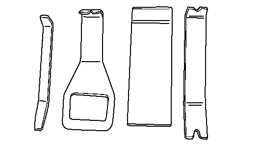
Special Service Tool
|
Tool number (TechMate No.) Tool name | Description | |
|---|---|---|
|
— (NI-46534) Trim Tool Set |
|
Removing trim components |
Ecu Diagnosis Information. Inverter Unit Nissan Pathfinder 5th Gen
Reference Value
TERMINAL LAYOUT
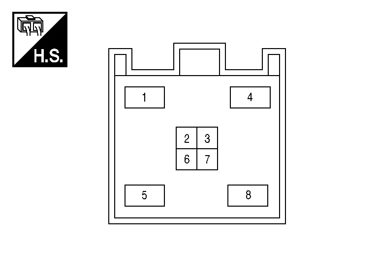
PHYSICAL VALUES
|
Terminal No. (Wire color) | Description | Condition |
Value (Approx.) | ||
|---|---|---|---|---|---|
| + | − | Signal name | Input/Output | ||
|
1 (P) |
5 (L) |
AC output 2 | Output | Ignition switch ON | 0 V |
| AC 120 V | |||||
|
Reference value
|
|||||
|
4 (R) |
Ground | Battery power supply | Input | Ignition switch OFF | Battery voltage |
|
5 (L) |
1 (P) |
AC output 1 | Output | Ignition switch ON | 0 V |
| AC 120 V | |||||
|
Reference value
|
|||||
|
6 (W) |
Ground | Ignition Switch ON or START | Input | Ignition switch ON | 0 V |
| Battery voltage | |||||
|
8 (B) |
Ground | Ground | — | Ignition switch OFF | 0 V |
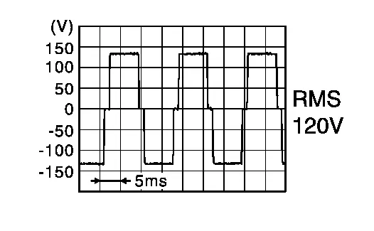

CAUTION:
-
To measure AC 120 V output signal, always use the circuit tester or oscilloscope AC range. Never allow the probes to contact each other.
-
Because of modified sine wave output of the AC 120 V output signal, voltage cannot be measured accurately without using a circuit tester that can measure true RMS (root mean square).
Fail-safe
When a malfunction listed below occurs, the inverter unit turns OFF.
| Malfunction item | Fail-safe condition | Fail-safe cancellation condition |
|---|---|---|
| Inverter unit power supply voltage is greater than 15 V. | When inverter unit input voltage rises above 15 V, the output will be suspended to protect the inverter unit. | After the inverter unit power supply voltage drops below 15 V, the ignition switch ON ⇒ OFF ⇒ ON operation allows normal return. |
| Inverter unit power supply voltage is less than 11.5 V for 2 seconds or more. | When inverter unit input voltage is lowered, the output will be suspended to protect the battery from running out. | After the inverter unit power supply voltage rises above 11.5 V, the ignition switch ON ⇒ OFF ⇒ ON operation allows normal return. |
| Inverter unit power supply voltage is less than 9 V. | ||
| Inverter unit AC 120 V output voltage is greater than 170 V. | When inverter unit AC 120 V output voltage is greater than 170 V, the output will be suspended. | After the inverter unit AC 120 V output voltage drops below 170 V, the ignition switch ON ⇒ OFF ⇒ ON operation allows normal return. |
| Inverter unit input current is greater than 13.3 A. | When inverter unit input current rises above 13.3 A, the output will be suspended to prevent over current (e.g., connecting an electric appliance exceeding rated output). | After the inverter unit input current drops below 13.3 A, the ignition switch ON ⇒ OFF ⇒ ON operation allows normal return. |
| Inverter unit is overheated. | When the inverter unit is overheated [thermistor temperature above 212° F (100° C)], the output will be suspended to protect the inverter unit. | After the inverter unit temperature is lowered, the ignition switch ON ⇒ OFF ⇒ ON operation allows normal return. |
| Inverter unit output signal (AC 120 V output signal) is shorted. | When inverter unit output signal is shorted, the output will be suspended. | After recovering from inverter unit output signal short, the ignition switch ON ⇒ OFF ⇒ ON operation allows normal return. |
Basic Inspection. Diagnosis and Repair Work Flow Nissan Pathfinder Fifth generation
Work Flow
OVERALL SEQUENCE
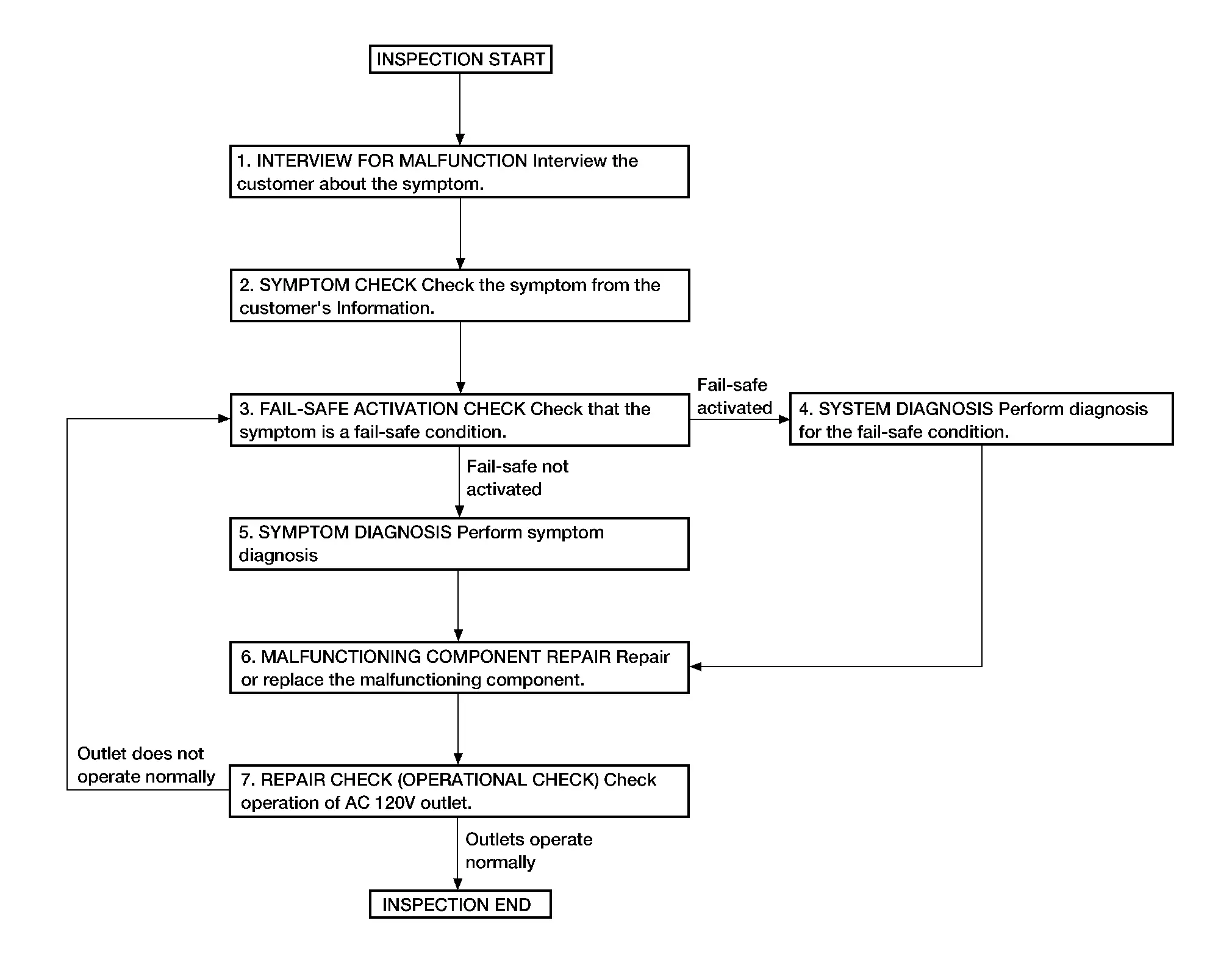
DETAILED FLOW
INTERVIEW FOR MALFUNCTION
Interview the customer about the symptom.
>>
GO TO 2.
SYMPTOM CHECK
Check the symptom from the customer's information.
>>
GO TO 3.
FAIL-SAFE ACTIVATION CHECK
Check that the symptom is a fail-safe condition.
Is fail-safe activated?
YES>>GO TO 4.
NO>>GO TO 5.
SYSTEM DIAGNOSIS
Perform diagnosis for the fail-safe activated system. Specify the malfunctioning component.
>>
GO TO 6.
SYMPTOM DIAGNOSIS
Perform symptom diagnosis. Specify the malfunctioning component.
>>
GO TO 6.
MALFUNCTIONING COMPONENT REPAIR
Repair or replace the malfunctioning component.
>>
GO TO 7.
REPAIR CHECK (OPERATIONAL CHECK)
Check operation of AC 120 V outlet.
Does the outlet operate normally?
YES>>Inspection End.
NO>>GO TO 3.
Service Data and Specifications (SDS) Nissan Pathfinder R53
AC 120V Power Outlet
| Rated voltage | AC 120 V |
| Maximum electric capacity | 150 W or less (Total) |
| Maximum current | Up to 1.25 A (Total) |

Nissan Pathfinder (R53) 2022-2026 Service Manual
Ac 120 V Outlet
- Precautions
- Preparation
- Ecu Diagnosis Information. Inverter Unit
- Basic Inspection. Diagnosis and Repair Work Flow
- Service Data and Specifications (SDS)
Contact Us
Nissan Pathfinder Info Center
Email: info@nipathfinder.com
Phone: +1 (800) 123-4567
Address: 123 Pathfinder Blvd, Nashville, TN 37214, USA
Working Hours: Mon–Fri, 9:00 AM – 5:00 PM (EST)
