Nissan Pathfinder: Engine Control System - Ecu Diagnosis Information
Ecm ➤ Nissan Pathfinder
Electric Intake Valve Timing Control Module Nissan Pathfinder SUV
Reference Value
TERMINAL LAYOUT

PHYSICAL VALUES
 NOTE:
NOTE:
-
Specification data are reference values and are measured between each terminal and ground.
-
Pulse signal is measured by CONSULT.
| Terminal No. | Description | Condition |
Value (Approx.) | ||
|---|---|---|---|---|---|
| + | − | Signal name | Input/Output | ||
|
1 (Y) |
3 (B) |
Power supply | — | [Ignition switch: ON] |
BATTERY VOLTAGE (11 – 14 V) |
|
2 (P) |
3 (B) |
Power supply | — | [Ignition switch: ON] |
BATTERY VOLTAGE (11 – 14 V) |
|
3 (B) |
— | Ground | — | — | — |
|
82 (Y) |
3 (B) |
Sensor power supply | — | [Ignition switch: ON] | 5 V |
|
83 (L) |
— | Electric intake valve timing control motor 2 hall sensor 1 | Input |
[Engine is running]
|
5 V |
|
84 (L) |
— | Electric intake valve timing control motor 2 temperature sensor | Input |
[Engine is running]
|
1.0 – 2.0 V |
|
90 (R) |
3 (B) |
Electric intake valve timing control motor 2 hall sensor 3 | Input |
[Engine is running]
|
5 V |
|
91 (G) |
3 (B) |
Electric intake valve timing control motor 2 hall sensor 2 | Input |
[Engine is running]
|
5 V |
|
92 (W) |
— | Sensor ground | — | — | — |
|
95 (W) |
3 (B) |
Ignition switch | — | — | — |
|
97 (B) |
3 (B) |
Crankshaft position sensor (electric intake valve timing control signal) | Input |
[Engine is running]
|
3.1 V
|
|
[Engine is running]
|
3.1 V
|
||||
|
98 (R) |
3 (B) |
Electric intake valve timing control motor 1 hall sensor 3 | Input |
[Engine is running]
|
5 V |
|
99 (G) |
3 (B) |
Electric intake valve timing control motor 1 hall sensor 2 | Input |
[Engine is running]
|
5 V |
|
100 (W) |
— | Sensor ground | — | — | — |
|
102 (P) |
— | ENGINE communication line-L | Input/Output | — | — |
|
104 (W) |
3 (B) |
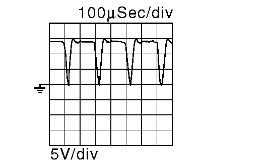
Intake camshaft position sensor (bank 2) (electric intake valve timing control signal) | Input |
[Engine is running]
|
4.1 V
|
|
[Engine is running]
|
4.1 V
|
||||
|
106 (Y) |
3 (B) |
Sensor power supply | — | [Ignition switch: ON] | 5 V |
|
107 (L) |
3 (B) |
Electric intake valve timing control motor 1 hall sensor 1 | Input |
[Engine is running]
|
5 V |
|
108 (L) |
3 (B) |
Electric intake valve timing control motor 1 temperature sensor | Input |
[Engine is running]
|
1.0 – 2.0 V |
|
110 (GR) |
— | Shield | — | — | — |
|
111 (GR) |
3 (B) |
ENGINE communication line-H | Input/Output | — | — |
|
113 (R) |
3 (B) |
Intake camshaft position sensor (bank 1) (electric intake valve timing control signal) | Input |
[Engine is running]
|
3.8 V
|
|
[Engine is running]
|
3.8 V
|
||||
|
114 (W) |
3 (B) |
Electric intake valve timing control motor 1 phase 3 | Input/Output |
[Engine is running]
|
BATTERY VOLTAGE (11 – 14 V) |
|
116 (W) |
3 (B) |
Electric intake valve timing control motor 2 phase 3 | Input/Output |
[Engine is running]
|
BATTERY VOLTAGE (11 – 14 V) |
|
117 (B) |
3 (B) |
Electric intake valve timing control motor 1 phase 2 | Input/Output |
[Engine is running]
|
BATTERY VOLTAGE (11 – 14 V) |
|
118 (B) |
3 (B) |
Electric intake valve timing control motor 2 phase 2 | Input/Output |
[Engine is running]
|
BATTERY VOLTAGE (11 – 14 V) |
|
119 (R) |
3 (B) |
Electric intake valve timing control motor 1 phase 1 | Input/Output |
[Engine is running]
|
BATTERY VOLTAGE (11 – 14 V) |
|
121 (R) |
3 (B) |
Electric intake valve timing control motor 2 phase 1 | Input/Output |
[Engine is running]
|
BATTERY VOLTAGE (11 – 14 V) |


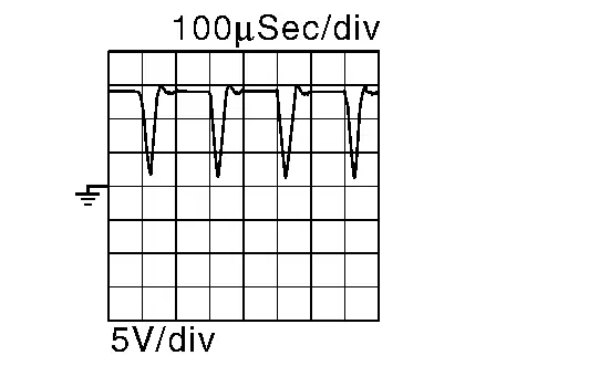

 : Average voltage for pulse signal (Actual pulse signal can be confirmed by oscilloscope.)

Nissan Pathfinder (R53) 2022-2026 Service Manual
Ecu Diagnosis Information
Contact Us
Nissan Pathfinder Info Center
Email: info@nipathfinder.com
Phone: +1 (800) 123-4567
Address: 123 Pathfinder Blvd, Nashville, TN 37214, USA
Working Hours: Mon–Fri, 9:00 AM – 5:00 PM (EST)
