Nissan Pathfinder: Ecu Diagnosis Information - Ecm ++
Values on the Diagnosis Tool
 NOTE:
NOTE:
-
The following table includes information (items) inapplicable to this Nissan Pathfinder vehicle. For information (items) applicable to this vehicle, refer to CONSULT display items.
-
Numerical values in the following table are reference values.
-
These values are input/output values that ECM receives/transmits and may differ from actual operations.
Example: The ignition timing shown by the timing light may differ from the ignition timing displayed on the data monitor.
This occurs because the timing light shows a value calculated by ECM according to signals received from the camshaft position sensor and other sensors related to ignition timing.
-
For outlines of following items, refer to CONSULT Function.
| Monitor Item | Condition | Values/Status | |
|---|---|---|---|
| COOLANT TEMP/S | Engine: After warming up | More than 70°C (158°F) | |
| VHCL SPEED SE | Turn drive wheels and compare CONSULT value with the speedometer indication. | Almost the same speed as speedometer indication | |
| BATTERY VOLT | Ignition switch: ON (Engine stopped) | 11 – 14 V | |
| INT/A TEMP SE | Ignition switch: ON | Indicates intake air temperature | |
| PURG VOL C/V |
|
Idle (Accelerator pedal: Not depressed even slightly, after engine starting.) |
Approx. 0% |
| 2,000 rpm | — | ||
| FUEL T/TMP SE | Ignition switch: ON | Indicates fuel tank temperature | |
| FUEL LEVEL SE | Ignition switch: ON | Depending on fuel level of fuel tank | |
| EVAP SYS PRES | Ignition switch: ON | 1.8 – 4.8 V | |
| CAL/LD VALUE |
|
Idle | 5 – 35% |
| 2,500 rpm | 5 – 35% | ||
| HO2S2 (B1) |
Revving engine from idle up to 3,000 rpm quickly after the following conditions are met.
|
0 – 0.3 V ←→ 0.6 – 1.0 V | |
| HO2S2 (B2) |
Revving engine from idle up to 3,000 rpm quickly after the following conditions are met.
|
0 – 0.3 V ←→ 0.6 – 1.0 V | |
| ENG OIL TEMP | Engine: After warming up | More than 70°C (158°F) | |
| A/F ALPHA-B1 | See Diagnosis Procedure. | ||
| A/F ALPHA-B2 | See Diagnosis Procedure. | ||
| A/F S1 HTR(B1) |
Engine: After warming up, idle the engine (More than 140 seconds after starting engine) |
4 – 100% | |
| A/F S1 HTR(B2) |
Engine: After warming up, idle the engine (More than 140 seconds after starting engine) |
4 – 100% | |
| EXH/V TIM B1 |
|
Idle | Approx. 0.0°CA |
| 3,000 rpm | Approx. 7°CA | ||
| EXH/V TIM B2 |
|
Idle | Approx. 0.0°CA |
| 3,000 rpm | Approx. 7°CA | ||
| Ignition timing |
|
Idle | Approx. 15 deg |
| 2,000 rpm | Approx. 47 deg | ||
| FAN DUTY | Engine: Running | 0 – 100% | |
| FUEL PUMP DUTY |
|
Idle | 90 |
| THRTL STK CNT B1 | This item is displayed but is not applicable to this model. | ||
| ENG SPEED | Run engine and compare CONSULT value with the tachometer indication. | Almost the same speed as the tachometer indication | |
| TRVL AFTER MIL | Ignition switch: ON | Nissan Pathfinder Vehicle has traveled after MIL has illuminated. |
0 – 655,350 km (0 – 407,234 miles) |
| B/FUEL SCHDL | See Diagnosis Procedure. | ||
| MASS AIRFLOW |
|
Idle | 1.8 – 3.0 g/s |
| 2,500 rpm | 8.6 – 14.5 g/s | ||
| FUEL PRES SEN |
|
Idle | 5.2 – 6.8 MPa |
| 2,000 rpm | 6.0 – 7.8 MPa | ||
| ACCEL SEN 1 |
Ignition switch: ON (Engine stopped) |
Accelerator pedal: Fully released | 0.45 – 1.00 V |
| Accelerator pedal: Fully depressed | 4.4 – 4.8 V | ||
| ACCEL SEN 2*1 |
Ignition switch: ON (Engine stopped) |
Accelerator pedal: Fully released | 0.45 – 1.00 V |
| Accelerator pedal: Fully depressed | 4.3 – 4.8 V | ||
| TP SEN 1-B1 |
|
Accelerator pedal: Fully released | More than 0.360 V |
| Accelerator pedal: Fully depressed | Less than 4.750 V | ||
| TP SEN 2-B1*1 |
|
Accelerator pedal: Fully released | More than 0.360 V |
| Accelerator pedal: Fully depressed | Less than 4.750 V | ||
| FUEL INJ B1 |
|
Idle | Approx. 1.0 msec |
| 2,000 rpm | Approx. 0.8 msec | ||
| FUEL INJ B2 |
|
Idle | Approx. 1.0 msec |
| 2,000 rpm | Approx. 0.8 msec | ||
| I/P PULLY SPD | Nissan Pathfinder Vehicle speed: More than 20 km/h (12 MPH) | Almost the same speed as the tachometer indication | |
| Nissan Pathfinder Vehicle SPEED | Turn drive wheels and compare CONSULT value with the speedometer indication. | Almost the same speed as the speedometer indication | |
| AC PRESS SEN |
|
1.0 – 4.0 V | |
| A/F SEN1 (B1) | Engine: After warming up | Maintaining engine speed at 2,000 rpm | Fluctuates around 2.2 V |
| A/F SEN1 (B2) | Engine: After warming up | Maintaining engine speed at 2,000 rpm | Fluctuates around 2.2 V |
| VHCL SPEED SE | Turn drive wheels and compare CONSULT value with the speedometer indication. | Almost the same speed as speedometer indication | |
| VTC DTY EX B1 |
|
Idle | Approx. 0% |
| Revving engine from idle up to 3,000 rpm quickly | Approx. 0%⇒ Approx. 40% | ||
| VTC DTY EX B2 |
|
Idle | Approx. 0% |
| Revving engine from idle up to 3,000 rpm quickly | Approx. 0%⇒ Approx. 40% | ||
| A/F ADJ-B1 | Engine: Running | −0.330 – 0.330 | |
| A/F ADJ-B2 | Engine: Running | −0.330 – 0.330 | |
| INT/V TIM (B1) |
|
Idle | − 5 – 5°CA |
| 2,000 rpm | 0 – 14°CA | ||
| INT/V TIM (B2) |
|
Idle | − 5 – 5°CA |
| 2,000 rpm | 0 – 14°CA | ||
| H/P FUEL PUMP DEG |
|
Idle | 255 – 275 deg |
| 2,000 rpm | 254 – 274 deg | ||
| FUEL PRES SEN V |
|
Idle | 1.120 – 1.310 V |
| 2,000 rpm | 1.215 – 1.425 V | ||
| EOP SENSOR |
|
Idle | 1.570 – 1.900 V |
| 2,000 rpm | 1.610 – 2.120 V | ||
| ECM TEMP 1 |
|
Idle | Approx. 95.225°F |
| 2,000 rpm | Approx. 97.475°F | ||
| ECM TEMP 2 |
|
Idle | Approx. 94.100°F |
| 2,000 rpm | Approx. 96.350°F | ||
| Mass air flow sensor (HZ) B1 | See Diagnosis Procedure. | ||
| LOAD SIGNAL | Ignition switch: ON |
Rear window defogger switch: ON and/or Lighting switch: 2nd position |
On |
| Rear window defogger switch and lighting switch: OFF | Off | ||
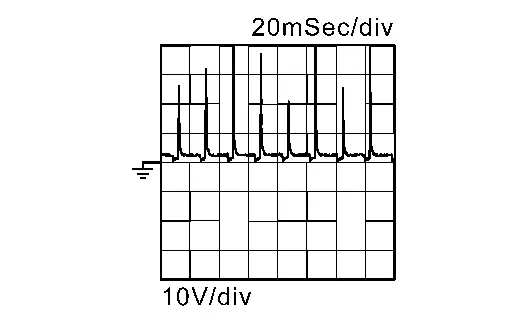
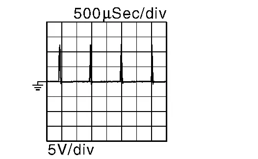
| AIR COND SIG | Engine: After warming up, idle the engine | Air conditioner switch: OFF | Off |
|
Air conditioner switch: ON (Compressor operates.) |
On | ||
| PW/ST SIGNAL | Engine: After warming up, idle the engine | Steering wheel: Not being turned | Off |
| Steering wheel: Being turned | On | ||
| P/N POSI SW | Ignition switch: ON | Selector lever: P or N | On |
| Selector lever: Except above | Off | ||
| START SIGNAL | Ignition switch: ON → START → ON | Off → On → Off | |
| CLSD THL POS |
Ignition switch: ON (Engine stopped) |
Accelerator pedal: Fully released | On |
| Accelerator pedal: Slightly depressed | Off | ||
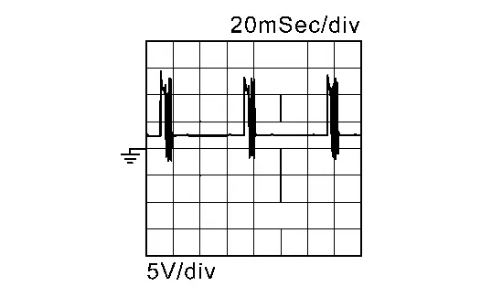
| HO2S2 MNTR(B1) |
Revving engine from idle up to 3,000 rpm quickly after the following conditions are met.
|
LEAN ←→ RICH | |
| HO2S2 MNTR(B2) |
Revving engine from idle up to 3,000 rpm quickly after the following conditions are met.
|
LEAN ←→ RICH | |
| IGNITION SW | Ignition switch: ON → OFF → ON | On → Off → On | |
| HEATER FAN SW | Engine: After warming up, idle the engine | Heater fan switch: ON | On |
| Heater fan switch: OFF | Off | ||
| IDL A/V LEARN | Engine: Running | Idle air volume learning has not been performed yet. | Yet |
| Idle air volume learning has already been performed successfully. | CMPLT | ||
| BRAKE SW | Ignition switch: ON | Brake pedal: Fully released | Off |
| Brake pedal: Slightly depressed | On | ||
| COMBUSTION |
|
Idle | Mode1 |
| 2,000 rpm | Mode1 | ||
| VIAS S/V-1 |
|
When revving engine up to 5,000 rpm quickly | Off →On → Off |
| ENGINE MOUNT | Engine: After warming up | Below 950 rpm | IDLE |
| Above 950 rpm | TRVL | ||
| FUEL PUMP RLY |
|
On | |
| Except above | Off | ||
| FPCM | Ignition switch: OFF | Off | |
|
Hi | ||
| Engine: Cranking | Hi | ||
| VENT CONT/V | Ignition switch: ON | Off | |
| THRTL RELAY | Ignition switch: ON | On | |
| HO2S2 HTR (B1) |
Engine speed: Below 3,600 rpm after the following conditions are met.
|
On | |
| Engine speed: Above 3,600 rpm | Off | ||
| HO2S2 HTR (B2) |
Engine speed: Below 3,600 rpm after the following conditions are met.
|
On | |
| Engine speed: Above 3,600 rpm | Off | ||
| DIST SW | Ignition switch: ON | DISTANCE switch: Pressed | On |
| DISTANCE switch: Released | Off | ||
| BRAKE SW2 | Ignition switch: ON | Brake pedal: Fully released | Off |
| Brake pedal: Slightly depressed | On | ||
| BRAKE SW1 | Ignition switch: ON | Brake pedal: Fully released | On |
| Brake pedal: Slightly depressed | Off | ||
| SET SW | Ignition switch: ON | COAST/SET switch: Pressed | On |
| COAST/SET switch: Released | Off | ||
| RESUME/ACC SW | Ignition switch: ON | ACCEL/RES switch: Pressed | On |
| ACCEL/RES switch: Released | Off | ||
| CANCEL SW | Ignition switch: ON | CANCEL switch: Pressed | On |
| CANCEL switch: Released | Off | ||
| MAIN SW | Ignition switch: ON | MAIN switch: Pressed | On |
| MAIN switch: Released | Off | ||
| CRUISE LAMP | Ignition switch: ON | MAIN switch: Pressed at the 1st time → at the 2nd time | On → Off |
| VIAS S/V-2 |
|
When revving engine up to 5,000 rpm quickly | Off →On → Off |
| HO2 S2 DIAG1(B2) | DTC P0159 self-diagnosis (delayed response) is incomplete. | INCMP | |
| DTC P0159 self-diagnosis (delayed response) is complete. | CMPLT | ||
| HO2 S2 DIAG1(B1) | DTC P0139 self-diagnosis (delayed response) is incomplete. | INCMP | |
| DTC P0139 self-diagnosis (delayed response) is complete. | CMPLT | ||
| HO2 S2 DIAG2(B2) | DTC P0159 self-diagnosis (slow response) is incomplete. | INCMP | |
| DTC P0159 self-diagnosis (slow response) is complete. | CMPLT | ||
| HO2 S2 DIAG2(B1) | DTC P0139 self-diagnosis (slow response) is incomplete. | INCMP | |
| DTC P0139 self-diagnosis (slow response) is complete. | CMPLT | ||
| EVAP LEAK DIAG | Ignition switch: ON | Depending on condition of EVAP leak diagnosis | |
| EVAP DIAG READY | Ignition switch: ON | Depending on ready condition of EVAP leak diagnosis | |
| SYSTEM 1 DIAGNOSIS A B2 | DTC P219B self-diagnosis is incomplete. | INCMP | |
| DTC P219B self-diagnosis is complete. | CMPLT | ||
| SYSTEM 1 DIAGNOSIS A B1 | DTC P219A self-diagnosis is incomplete. | INCMP | |
| DTC P219A self-diagnosis is complete. | CMPLT | ||
| A/F SEN1 DIAG1(B2) | DTC P015C and P015D self-diagnosis incomplete. | INCMP | |
| DTC P015C and P015D self-diagnosis is complete. | CMPLT | ||
| A/F SEN1 DIAG1(B1) | DTC P015A and P015B self-diagnosis incomplete. | INCMP | |
| DTC P015A and P015B self-diagnosis is complete. | CMPLT | ||
| A/F SEN1 DIAG2(B2) | DTC P014E and P014F self-diagnosis incomplete. | INCMP | |
| DTC P014E and P014F self-diagnosis is complete. | CMPLT | ||
| A/F SEN1 DIAG2(B1) | DTC P014C and P014D self-diagnosis incomplete. | INCMP | |
| DTC P014C and P014D self-diagnosis is complete. | CMPLT | ||
| SYSTEM 1 DIAGNOSIS B B2 | DTC P219B self-diagnosis is on standby. | ABSENT | |
| DTC P219B self-diagnosis is under diagnosis. | PRSENT | ||
| SYSTEM 1 DIAGNOSIS B B1 | DTC P219A self-diagnosis is on standby. | ABSENT | |
| DTC P219A self-diagnosis is under diagnosis. | PRSENT | ||
| A/F SEN1 DIAG3(B2) | The Nissan Pathfinder vehicle condition is not within the diagnosis range of DTC P014E, P014F, P015C or P015D. | ABSNT | |
| The Nissan Pathfinder vehicle condition is within the diagnosis range of DTC P014E, P014F, P015C or P015D. | PRSNT | ||
| A/F SEN1 DIAG3(B1) | The Nissan Pathfinder vehicle condition is not within the diagnosis range of DTC P014C, P014D, P015A or P015B. | ABSNT | |
| The Nissan Pathfinder vehicle condition is within the diagnosis range of DTC P014C, P014D, P015A or P015B. | PRSNT | ||
| ATOM PRES SEN 2 | Ignition switch: ON | 0 V | |
| A/GRLL SHTTR POSITION |
|
F/OPEN | |
|
Nissan Pathfinder Vehicle speed: 30 km/h (19 MPH) or faster. (Comply the condition of active grille shutter operation.) |
F/OPEN →MOVING→F/CLOSE | ||
| STRT OPR TN CNTR | Ignition switch: ON | Indicated multiplication value of the starter motor operation | |
| A/F LRN CNTR B2 |
This item is displayed but are not applicable to this model. |
— | |
| A/F LRN CNTR B1 |
This item is displayed but are not applicable to this model. |
— | |
| TOTAL DISTNC-OCS RST 1 | Ignition switch: ON | Varies depending on Nissan Pathfinder vehicle environment. |
0 - 655,350 km (0 - 407,234 miles) |
| TOTAL DISTNC-OCS RST 2 | Ignition switch: ON | Varies depending on Nissan Pathfinder vehicle environment. |
0 - 655,350 km (0 - 407,234 miles) |
| TOTAL DISTNC-OCS RST 3 | Ignition switch: ON | Varies depending on Nissan Pathfinder vehicle environment. |
0 - 655,350 km (0 - 407,234 miles) |
| DETERIORTN VL-OCS RST 1 | Ignition switch: ON | Varies depending on Nissan Pathfinder vehicle environment. | 0 - 655.35 |
| DETERIORTN VL-OCS RST 2 | Ignition switch: ON | Varies depending on Nissan Pathfinder vehicle environment. | 0 - 655.35 |
| DETERIORTN VL-OCS RST 3 | Ignition switch: ON | Varies depending on Nissan Pathfinder vehicle environment. | 0 - 655.35 |
| TOTAL DISTNC-OCS WRN 1 | Ignition switch: ON | Varies depending on Nissan Pathfinder vehicle environment. |
0 - 655,350 km (0 - 407,234 miles) |
| TOTAL DISTNC-OCS WRN 2 | Ignition switch: ON | Varies depending on Nissan Pathfinder vehicle environment. |
0 - 655,350 km (0 - 407,234 miles) |
| TOTAL DISTNC-OCS WRN 3 | Ignition switch: ON | Varies depending on Nissan Pathfinder vehicle environment. |
0 - 655,350 km (0 - 407,234 miles) |
| DETERIORTN VL-OCS WRN 1 | Ignition switch: ON | Varies depending on Nissan Pathfinder vehicle environment. | 0 - 655.35 |
| DETERIORTN VL-OCS WRN 2 | Ignition switch: ON | Varies depending on Nissan Pathfinder vehicle environment. | 0 - 655.35 |
| DETERIORTN VL-OCS WRN 3 | Ignition switch: ON | Varies depending on Nissan Pathfinder vehicle environment. | 0 - 655.35 |
| CURRENT DETERIORA TN VAL | Ignition switch: ON | Varies depending on Nissan Pathfinder vehicle environment. | 0 - 655.35 |
| Brake operation judgment | Ignition switch: ON | Off | |
| A/GRLL SHTTR CALIBRATION |
|
CMPLT | |
|
INCMP | ||
| A/GRLL SHTTR CIRCUIT DIAG | Malfunction of active grill shutter power supply is detected. | NG | |
| Malfunction of active grill shutter power supply is not detected. | OK | ||
| A/GRLL SHTTR TEMP DIAG | Abnormal temperature of active grill shutter actuator is detected. | NG | |
| Abnormal temperature of active grill shutter actuator is not detected. | OK | ||
| A/GRLL SHTTR OVERRUN | Active grill shutter does not stop within normal moving limit. | NG | |
| Active grill shutter does not stop within normal moving limit. | OK | ||
| A/GRLL SHTTR STUCK | Detecting the active grille shutter stuck or the operation range less than normal. | NG | |
| Detecting the active grille shutter stuck or the operation range less than normal. | OK | ||
| A/GRLL SHTTR CALIB DIAG | Malfunction of active grill shutter initial position learning is detected. | NG | |
| Malfunction of active grill shutter initial position learning is not detected. | OK | ||
| Starter motor (Counter) | Ignition switch: ON | OK | |
| Driver's seat belt switch | Ignition switch: ON | OK | |
| Engine parts | Ignition switch: ON | OK | |
| ABS error | Ignition switch: ON | OK | |
| TCM error A | Ignition switch: ON | OK | |
| TCM error B | Ignition switch: ON | OK | |
| VDC error | Ignition switch: ON | OK | |
| IPDM error | Ignition switch: ON | OK | |
| CAN comm (VDC) A | Ignition switch: ON | OK | |
| CAN comm (VDC) B | Ignition switch: ON | OK | |
| CAN comm (VDC) C | Ignition switch: ON | OK | |
| CAN comm (VDC) D | Ignition switch: ON | OK | |
| CAN comm (VDC) E | Ignition switch: ON | OK | |
| CAN comm (VDC) F | Ignition switch: ON | OK | |
| CAN comm (VDC) G | Ignition switch: ON | OK | |
| CAN comm (VDC) H | Ignition switch: ON | OK | |
| CAN comm (TCM) A | Ignition switch: ON | OK | |
| CAN comm (TCM) B | Ignition switch: ON | OK | |
| CAN comm (TCM) C | Ignition switch: ON | OK | |
| CAN comm (TCM) D | Ignition switch: ON | OK | |
| CAN comm (TCM) E | Ignition switch: ON | OK | |
| CAN comm (BCM) A | Ignition switch: ON | OK | |
| CAN comm (BCM) B | Ignition switch: ON | OK | |
| CAN comm (BCM) C | Ignition switch: ON | OK | |
| CAN comm (BCM) D | Ignition switch: ON | OK | |
| CAN comm (BCM) E | Ignition switch: ON | OK | |
| CAN comm (IPDM) A | Ignition switch: ON | OK | |
| CAN comm (IPDM) B | Ignition switch: ON | OK | |
| CAN comm (IPDM) C | Ignition switch: ON | OK | |
| CAN comm (IPDM) D | Ignition switch: ON | OK | |
| CAN comm (IPDM) E | Ignition switch: ON | OK | |
| Starter motor relay | Ignition switch: ON | OK | |
| Neutral switch | Ignition switch: ON | OK | |
| Clutch switch (Lower) | Ignition switch: ON | OK | |
| Clutch switch (Upper) | Ignition switch: ON | OK | |
| CAN comm (EPS) | Ignition switch: ON | OK | |
| LIN comm (DC/DC) | Ignition switch: ON | OK | |
| Negative pressure | Ignition switch: ON | OK | |
 NOTE:
NOTE:
 NOTE:
NOTE:
*1: Accelerator pedal position sensor 2 signal and throttle position sensor 2 signal are converted by ECM internally. Thus, they differ from ECM terminals voltage signal.
*2: Before measuring the terminal voltage, confirm that the battery is fully charged. Refer to How to Handle Battery.
Reference Value
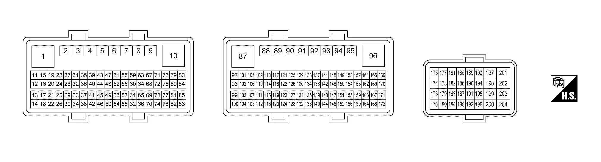
TERMINAL LAYOUT
PHYSICAL VALUES
 NOTE:
NOTE:
-
ECM is located behind the instrument assist lower panel. For this inspection, remove passenger side instrument lower panel.
-
Specification data are reference values and are measured between each terminal and ground.
-
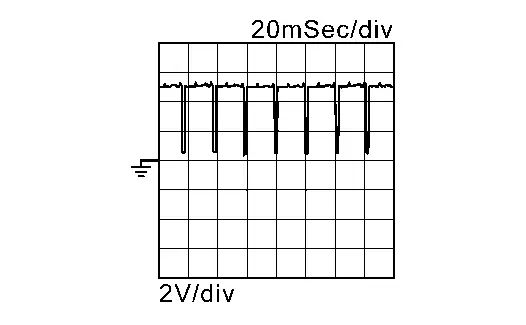
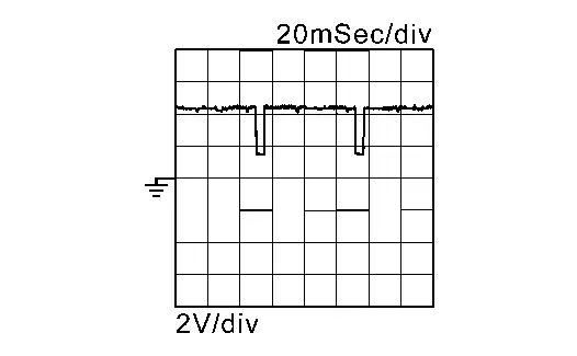
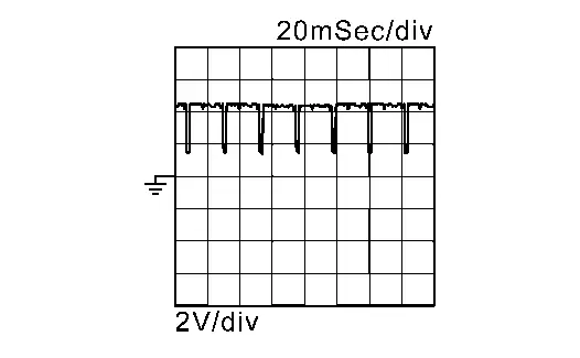
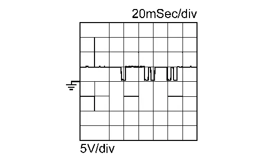
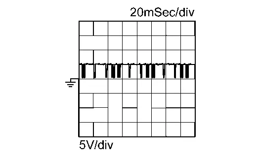
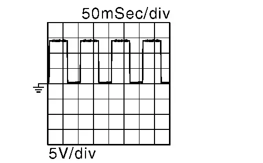
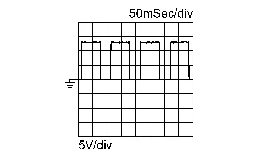
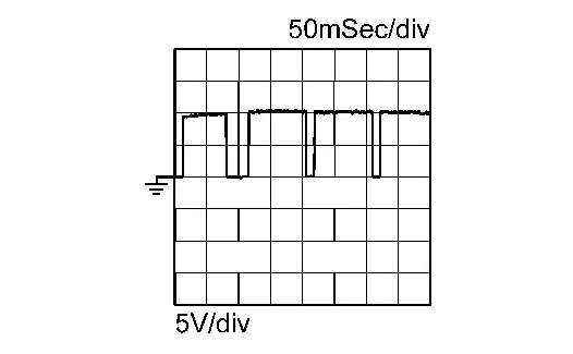
Pulse signal is measured by CONSULT.
|
Terminal No. (Wire color) | Description | Condition |
Value (Approx.) | ||
|---|---|---|---|---|---|
| + | − | Signal name | Input/Output | ||
|
1 (V) |
204 (B) |
Fuel injector driver power supply a1 | Input | [Ignition switch: ON] |
BATTERY VOLTAGE (11 – 14 V) |
|
2 (B) |
204 (B) |
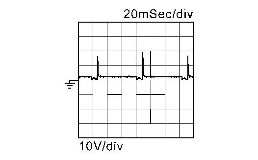
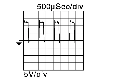
High pressure fuel pump (LO) | Output | [Ignition switch: ON] | 2.43 V |
|
[Engine is running]
The pulse cycle changes depending on rpm at idle |
|
||||
|
[Engine is running]
|
|
||||
|
3 (B) |
— | Fuel injector driver ground 1 | — | — | — |
|
4 (W) |
204 (B) |
High pressure fuel pump (HI) | Output | [Ignition switch: ON] | 2.43 V |
|
[Engine is running]
The pulse cycle changes depending on rpm at idle |
|
||||
|
[Engine is running]
|
|
||||
|
5 (SB) |
204 (B) |
Heated oxygen sensor 2 heater (bank 2) | Output |
[Engine is running] Engine speed: Below 3,600 rpm after the following conditions are met
|
10 V
|
|
[Ignition switch: ON] Engine stopped [Engine is running] Engine speed: Above 3,600 rpm |
BATTERY VOLTAGE (11 - 14 V) |
||||
|
6 (L) |
204 (B) |
Heated oxygen sensor 2 heater (bank 1) | Output |
[Engine is running] Engine speed: Below 3,600 rpm after the following conditions are met
|
10 V
|
|
[Ignition switch: ON] Engine stopped [Engine is running] Engine speed: Above 3,600 rpm |
BATTERY VOLTAGE (11 – 14 V) |
||||
|
7 (B) |
8 (GR) |
Knock sensor (bank 1) | Input | [Ignition switch: ON] | 2.43 V |
|
[Engine is running] Idle speed |
2.47 V*1 | ||||
|
8 (GR) |
— |
Sensor ground (Knock sensor) |
— | — | — |
|
10 (Y) |
204 (B) |
Fuel injector driver power supply a2 | Input | [Ignition switch: ON] |
BATTERY VOLTAGE (11 – 14 V) |
|
11 (O) 14 (Y) 15 (BR) 18 (W) 24 (R) 25 (P) |
204 (B) |
Fuel injector No.4 (LO) Fuel injector No.2 (LO) Fuel injector No.1 (LO) Fuel injector No.5 (LO) Fuel injector No.6 (LO) Fuel injector No.3 (LO) |
Output | [Ignition switch: ON] | 2.44 V |
|
[Engine is running]
The pulse cycle changes depending on rpm at idle |
2.55 V
|
||||
|
12 (Y) 13 (B) 16 (W) 17 (L) 20 (L) 21 (G) |
204 (B) |
Fuel injector No.1 (HI) Fuel injector No.5 (HI) Fuel injector No.4 (HI) Fuel injector No.2 (HI) Fuel injector No.3 (HI) Fuel injector No.6 (HI) |
Output | [Ignition switch: ON] | 2.44 V |
|
[Engine is running]
The pulse cycle changes depending on rpm at idle |
2.6 V
|
||||
|
22 (BR) |
— |
Sensor ground (Crankshaft position sensor 1) |
— | — | — |
|
23 (B) |
— | Shield | — | — | — |
|
27 (V) |
— |
Sensor ground [Intake camshaft position sensor (bank 1)] |
— | — | — |
|
28 (BR) |
— |
Sensor ground [Exhaust camshaft position sensor (bank 1)] |
— | — | — |
|
29 (B) |
— |
Sensor ground (Engine oil pressure sensor, Engine coolant temperature sensor, Engine oil temperature sensor) |
— | — | — |
|
30 (R) |
— |
Sensor ground (Mass air flow sensor, Intake air temperature sensor) |
— | — | — |
|
31 (GR) |
22 (BR) |
Crankshaft position sensor 1 | Input |
[Engine is running]
|
|
|
[Engine is running]
|
|
||||
|
32 (B) |
204 (B) |
Crankshaft position sensor (Electric intake valve timing control signal) | Output |
[Engine is running]
|
|
|
[Engine is running]
|
|
||||
|
33 (W) |
30 (R) |
Mass air flow sensor | Input |
[Ignition switch: ON]
|
3,700 Hz
|
|
[Engine is running]
|
4,714 – 5,880 Hz
|
||||
|
[Engine is running]
|
6,080 – 6,600 Hz
|
||||
|
[Engine is running]
|
4,714 – 5,880 Hz → 7,200 Hz
|
||||
|
34 (LG) |
28 (BR) |
Exhaust camshaft position sensor (bank 1) | Input |
[Engine is running]
|
|
|
[Engine is running]
|
|
||||
|
36 (SB) |
27 (V) |
Intake camshaft position sensor (bank 1) | Input |
[Engine is running]
|
4.0 – 5.0 V
|
|
[Engine is running]
|
4.0 – 5.0 V
|
||||
|
37 (R) |
27 (V) |
Intake camshaft position sensor (bank 1) (Electric intake valve timing control signal) | Output |
[Engine is running]
The pulse cycle changes depending on rpm at idle |
4.0 – 5.0 V
|
|
[Engine is running]
|
4.0 – 5.0 V
|
||||
|
38 (GR) |
204 (B) |
Sensor power supply [Exhaust camshaft position sensor (bank 1)] |
— | [Ignition switch: ON] | 5 V |
|
39 (LG) |
204 (B) |
Sensor power supply (Crankshaft position sensor 1) |
— | [Ignition switch: ON] | 5 V |
|
40 (LG) |
204 (B) |
Sensor power supply [Intake camshaft position sensor (bank 1)] |
— | [Ignition switch: ON] | 5 V |
|
41 (B) |
204 (B) |
Sensor power supply (Mass air flow sensor, Intake air temperature sensor) |
— | [Ignition switch: ON] | 5 V |
|
42 (Y) |
204 (B) |
Sensor power supply (Engine oil pressure sensor) |
— | [Ignition switch: ON] | 5 V |
|
43 (V) |
30 (R) |
Intake air temperature sensor | Input |
[Ignition switch: ON]
|
2.1 V |
|
47 (LG) |
85 (V) |
Fuel rail pressure sensor | Input |
[Engine is running]
|
1.12 – 1.31 V |
|
[Engine is running]
|
1.22 – 1.42 V | ||||
|
48 (BR) |
29 (B) |
Engine coolant temperature sensor | Input |
[Engine is running]
|
3.27 V |
|
[Engine is running]
|
2.33 V | ||||
|
[Engine is running]
|
1.26 V | ||||
|
49 (W) |
81 (B) |
Heated oxygen sensor 2 (bank 1) | Input |
[Engine is running]
|
0 – 1.0 V |
|
50 (R) |
29 (B) |
Engine oil temperature sensor | Input |
[Engine is running]
|
3.27 V |
|
[Engine is running]
|
2.33 V | ||||
|
[Engine is running]
|
1.26 V | ||||
|
51 (W) |
81 (B) |
Heated oxygen sensor 2 (bank 2) | Input |
[Engine is running] Revving engine from idle to 3,000 rpm quickly after the following conditions are met
|
0 – 1.0 V |
|
60 (GR) |
204 (B) |
Sensor power supply [Intake camshaft position sensor (bank 2)] |
— | [Ignition switch: ON] | 5 V |
|
62 (W) |
29 (B) |
Engine oil pressure sensor | Input |
[Engine is running]
|
1.57 – 1.90 V |
|
[Engine is running]
|
1.61 – 2.12 V | ||||
|
63 (L) |
204 (B) |
Sensor power supply (Crankshaft position sensor 2) |
— | [Ignition switch: ON] | 5 V |
|
65 (L) |
204 (B) |
Sensor power supply [Exhaust camshaft position sensor (bank 2)] |
— | [Ignition switch: ON] | 5 V |
|
66 (Y) |
204 (B) |
Sensor power supply (Fuel rail pressure sensor) |
— | [Ignition switch: ON] | 5 V |
|
67 (LG) |
76 (BR) |
Intake camshaft position sensor (bank 2) | Input |
[Engine is running]
|
4.0 – 5.0 V
|
|
[Engine is running]
|
4.0 – 5.0 V
|
||||
|
68 (W) |
204 (B) |
Intake camshaft position sensor (bank 2) (Electric intake valve timing control signal) | Output |
[Engine is running]
|
4.0 – 5.0 V
|
|
[Engine is running]
|
4.0 – 5.0 V
|
||||
|
72 (Y) |
— |
Sensor ground [Exhaust camshaft position sensor (bank 2)] |
— | — | — |
|
73 (LG) |
72 (Y) |
Exhaust camshaft position sensor (bank 2) | Input |
[Engine is running]
|
4.0 – 5.0 V
|
|
[Engine is running]
|
4.0 – 5.0 V
|
||||
|
74 (LG) |
77 (Y) |
Crankshaft position sensor 2 | Input |
[Engine is running]
|
4.0 V
|
|
[Engine is running]
|
4.0 V
|
||||
|
76 (BR) |
— |
Sensor ground [Intake camshaft position sensor (bank 2)] |
— | — | — |
|
77 (Y) |
— |
Sensor ground (Crankshaft position sensor 2) |
— | — | — |
|
81 (B) |
— |
Sensor ground [Heated oxygen sensor 2 (bank 1), Heated oxygen sensor 2 (bank 2)] |
— | — | — |
|
83 (L) |
— | Starter switch | — | — | — |
|
84 (P) |
204 (B) |
Fuel pump relay | Output |
[Ignition switch: ON] For 1 second after turning ignition switch ON [Engine is running] |
0 – 1.5 V |
|
[Ignition switch: ON] More than 1 second after turning ignition switch ON |
BATTERY VOLTAGE (11 – 14 V) |
||||
|
85 (V) |
— |
Sensor ground (Fuel rail pressure sensor) |
— | — | — |
|
86 (W) |
8 (GR) |
Knock sensor (bank 2) | Input | [Ignition switch: ON] | 2.44 V |
|
[Engine is running]
|
2.50 V*1 | ||||
|
87 (B) |
— | ECM ground | — | — | — |
|
91 (BR) |
204 (B) |
Air fuel ratio (A/F) sensor 1 heater (bank 1) | Output | [Ignition switch: ON] | 13.5 V |
|
[Engine is running]
|
10.1 V
|
||||
|
92 (SB) |
204 (B) |
Air fuel ratio (A/F) sensor 1 heater (bank 2) | Output | [Ignition switch: ON] | 13.5 V |
|
[Engine is running]
|
10.1 V
|
||||
|
95 (R) |
204 (B) |
Throttle control motor power supply | Input | [Ignition switch: ON] |
BATTERY VOLTAGE (11 – 14 V) |
|
97 (GR) |
— | Shield | — | — | — |
|
100 (R) |
— |
Sensor ground (Throttle position sensor) |
— | — | — |
|
101 (G) |
204 (B) |
Air fuel ratio (A/F) sensor 1 (bank 1) | Input |
[Engine is running]
|
2.7 V Output voltage varies with air fuel ratio. |
|
102 (R) |
204 (B) |
Air fuel ratio (A/F) sensor 1 (bank 1) | Input | [Ignition switch: ON] | 2.2 V |
|
103 (B) |
100 (R) |
Throttle position sensor 1 | Input |
[Ignition switch: ON]
|
More than 0.36 V |
|
[Ignition switch: ON]
|
Less than 4.75 V | ||||
|
105 (G) |
204 (B) |
Air fuel ratio (A/F) sensor 1 (bank 2) | Input |
[Engine is running]
|
2.7 V Output voltage varies with air fuel ratio. |
|
106 (R) |
204 (B) |
Air fuel ratio (A/F) sensor 1 (bank 2) | Input | [Ignition switch: ON] | 2.2 V |
|
108 (LG) |
125 (V) |
Refrigerant pressure sensor | Input |
[Engine is running]
|
1.0 – 4.0 V |
|
114 (W) |
100 (R) |
Throttle position sensor 2 | Input |
[Ignition switch: ON]
|
Less than 4.75 V |
|
[Ignition switch: ON]
|
More than 0.36 V | ||||
|
122 (SHIELD) |
— | Shield | — | — | — |
|
125 (V) |
— |
Sensor ground (Refrigerant pressure sensor) |
— | — | — |
|
129 (G) |
100 (R) |
Sensor power supply (Throttle position sensor) |
— | [Ignition switch: ON] | 5 V |
|
136 (BR) |
204 (B) |
Sensor power supply (Refrigerant pressure sensor) |
— | [Ignition switch: ON] | 5 V |
|
139 (G) |
204 (B) |
Throttle control motor relay | Output | [Ignition switch: ON → OFF] |
0 – 1.0 V ↓ BATTERY VOLTAGE (11 – 14 V) ↓ 0 V |
| [Ignition switch: ON] | 0 – 1.0 V | ||||
|
140 (V) |
204 (B) |
ECM relay (Self shut-off) |
Output |
[Engine is running] [Ignition switch: OFF] A few seconds after turning ignition switch OFF |
0 – 1.5 V |
|
[Ignition switch: OFF] More than a few seconds after turning ignition switch OFF |
BATTERY VOLTAGE (11 – 14 V) |
||||
|
142 (G) |
204 (B) |
Engine oil pressure control solenoid valve | Output |
[Engine is running]
|
BATTERY VOLTAGE (11 – 14 V) |
|
[Engine is running]
|
0 V | ||||
|
147 (W) |
148 (G) |
Throttle control motor (Open) | Output |
[Ignition switch: ON]
|
2.5 V
|
|
[Ignition switch: ON]
|
0.2 V
|
||||
|
148 (G) |
147 (W) |
Throttle control motor (Close) | Output |
[Ignition switch: ON]
|
0.2 V
|
|
[Ignition switch: ON]
|
0.3 V
|
||||
|
151 (P) |
204 (B) |
Electronic controlled engine mount control solenoid valve | Output |
[Engine is running]
|
0 – 1.0 V |
|
[Engine is running]
|
BATTERY VOLTAGE (11 – 14 V) |
||||
|
152 (Y) |
204 (B) |
EVAP canister purge volume control solenoid valve | Output |
[Engine is running]
|
BATTERY VOLTAGE (11 - 14 V)
|
|
[Engine is running]
|
12.2 V
|
||||
|
153 (P) 154 (V) 161 (Y) 162 (SB) 164 (R) 168 (LG) |
204 (B) |
Ignition signal No. 3 Ignition signal No. 6 Ignition signal No. 1 Ignition signal No. 4 Ignition signal No. 2 Ignition signal No. 5 |
Output | [Ignition switch: ON] | 0 V |
|
[Engine is running]
|
0.2 V
|
||||
|
[Engine is running]
|
0.4 V
|
||||
|
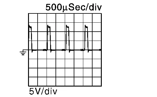
157 (BR) |
204 (B) |
Exhaust valve timing control solenoid valve (bank 1) | [Ignition switch: ON] | 13.8 V | |
|
[Ignition switch: ON]
|
9.2 V | ||||
|
159 (L) |
204 (B) |
Exhaust valve timing control solenoid valve (bank 2) | [Ignition switch: ON] | 13.8 V | |
|
[Ignition switch: ON]
|
9.2 V | ||||
|
163 (BR) |
204 (B) |
VIAS control solenoid valve 1 | Output |
[Engine is running]
|
BATTERY VOLTAGE (11 – 14 V) |
|
[Engine is running]
|
BATTERY VOLTAGE (11 – 14 V) ↓ 0 – 1.0 V ↓ BATTERY VOLTAGE (11 – 14 V) |
||||
|
165 (R) |
— | Drivetrain CAN communication-L | Input/output | — | — |
|
166 (W) |
204 (B) |
VIAS control solenoid valve 2 | Output |
[Engine is running]
|
BATTERY VOLTAGE (11 – 14 V) |
|
[Engine is running]
|
BATTERY VOLTAGE (11 – 14 V) ↓ 0 – 1.0 V ↓ BATTERY VOLTAGE (11 – 14 V) |
||||
|
167 (Y) |
— | LIN | — | — | — |
|
169 (GR) |
— | Drivetrain CAN communication-H | Input/output | — | — |
|
170 (GR) |
204 (B) |
Power supply for ECM (Back-up) | Input | [Ignition switch: ON] |
BATTERY VOLTAGE (11 – 14 V) |
|
173 (L) |
200 (G) |
EVAP control system pressure sensor | Input | [Ignition switch: ON] | 3.5 – 4.5 V |
|
[Ignition switch: ON]
|
3.5 – 4.5 V | ||||
|
175 (R) |
— | CAN-L | Input/output | — | — |
|
176 (GR) |
— | CAN-H | Input/output | — | — |
|
177 (R) |
204 (B) |
Sensor power supply (EVAP control system pressure sensor) |
— | [Ignition switch: ON] | 5 V |
|
180 (LA/BR) |
200 (G) |
Fuel tank temperature sensor | Input |
[Ignition switch: ON]
|
3.43 V |
|
182 (LA/SB) |
204 (B) |
Fuel pump control module (FPCM) check | Input | [Ignition switch: ON] | 0 V |
|
[Engine is running]
|
12.9 V | ||||
|
185 (W) |
204 (B) |
Ignition switch | Input | [Ignition switch: OFF] | 0 V |
| [Ignition switch: ON] |
BATTERY VOLTAGE (11 – 14 V) |
||||
|
186 (LA) |
187 (LA/P) |
ICC steering switch (models with ICC system) |
Input |
[Ignition switch: ON] MAIN switch: Pressed |
0 V |
|
[Ignition switch: ON] CANCEL switch: Pressed |
1.2 V | ||||
|
[Ignition switch: ON] DISTANCE switch: Pressed |
2.1 V | ||||
|
[Ignition switch: ON] COAST/SET switch: Pressed |
2.9 V | ||||
|
[Ignition switch: ON] ACCEL/RES switch: Pressed |
3.6 V | ||||
|
[Ignition switch: ON] ICC steering switch: OFF |
4.2 V | ||||
|
ASCD steering switch (models without ICC system) |
Input |
[Ignition switch: ON] MAIN switch: Pressed |
0 V | ||
|
[Ignition switch: ON] CANCEL switch: Pressed |
1 V | ||||
|
[Ignition switch: ON] COAST/SET switch: Pressed |
2 V | ||||
|
[Ignition switch: ON] ACCEL/RES switch: Pressed |
3 V | ||||
|
[Ignition switch: ON] ASCD steering switch: OFF |
4 V | ||||
|
187 (LA/P) |
— |
Sensor ground (ASCD/ICC steering switch) |
— | — | — |
|
188 (LA/GR) |
204 (B) |
Fuel pump control module (FPCM) | Output | [Ignition switch: ON] | 0 V |
|
[Engine is running]
|
0 V ←→ 12.9 V
|
||||
|
[When cranking engine] Not cold state condition |
0 V ←→ 10.7 V
|
||||
|
[Ignition switch: ON] For 1 second after turning ignition switch ON |
0 V ←→ 12.9 V
|
||||
|
189 (P) |
— | Engine communication line-L | Input/Output | — | — |
|
190 (GR) |
— | Engine communication line-H | Input/Output | — | — |
|
192 (V) |
204 (B) |
Brake pedal position switch | Input |
[Ignition switch: ON] Brake pedal: Slightly depressed |
0 V |
|
[Ignition switch: ON] Brake pedal: Fully released |
BATTERY VOLTAGE (11 – 14 V) |
||||
|
193 (LA/Y) |
204 (B) |
EVAP canister vent control valve | Output | [Ignition switch: ON] |
BATTERY VOLTAGE (11 – 14 V) |
|
194 (LA/B) |
204 (B) |
Sensor power supply (Accelerator pedal position sensor 2) |
— | [Ignition switch: ON] | 5 V |
|
195 (LA/W) |
196 (LA/V) |
Accelerator pedal position sensor 2 | Input |
[Ignition switch: ON]
|
0.22 – 0.50 V |
|
[Ignition switch: ON]
|
2.1 – 2.5 V | ||||
|
196 (LA/V) |
— |
Sensor ground (Accelerator pedal position sensor 2) |
— | — | — |
|
197 (LG) |
204 (B) |
Power supply for ECM | Input | [Ignition switch: ON] |
BATTERY VOLTAGE (11 – 14 V) |
|
198 (L) |
204 (B) |
Sensor power supply (Accelerator pedal position sensor 1) |
— | [Ignition switch: ON] | 5 V |
|
199 (B) |
— | ECM ground | — | — | — |
|
200 (G) |
— |
Sensor ground (EVAP control system pressure sensor, Fuel tank temperature sensor) |
— | — | — |
|
201 (B) |
— | ECM ground | — | — | — |
|
202 (G) |
203 (R) |
Accelerator pedal position sensor 1 | Input |
[Ignition switch: ON]
|
0.45 – 1.00 V |
|
[Ignition switch: ON]
|
4.4 – 4.8 V | ||||
|
203 (R) |
— |
Sensor ground (Accelerator pedal position sensor 1) |
— | — | — |
|
204 (B) |
— | ECM ground | — | — | — |
 NOTE:
NOTE:
 NOTE:
NOTE:


 NOTE:
NOTE:

 NOTE:
NOTE:

 NOTE:
NOTE:
 NOTE:
NOTE:


 NOTE:
NOTE:
 NOTE:
NOTE:


 NOTE:
NOTE:


 NOTE:
NOTE:


 NOTE:
NOTE:


 NOTE:
NOTE:


 NOTE:
NOTE:


 NOTE:
NOTE:


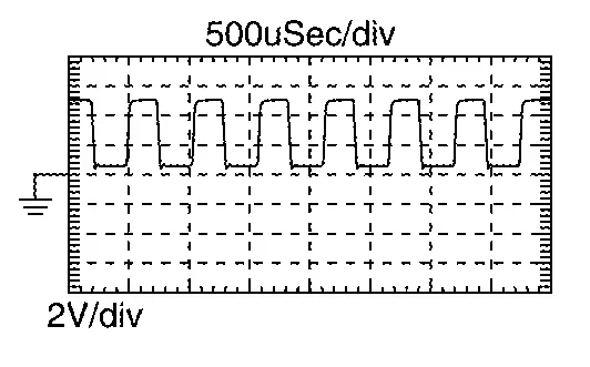
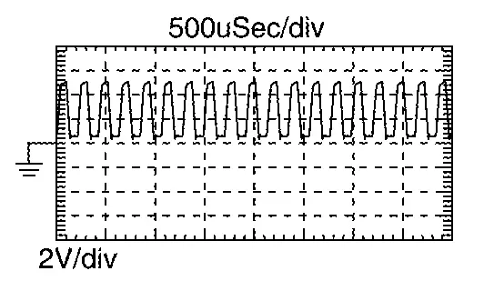
 : Average voltage for pulse signal (Actual pulse signal can be confirmed by oscilloscope.)
*1: This may vary depending on internal resistance of the tester.
*2: Before measuring the terminal voltage, confirm that the battery is fully charged. Refer to How to Handle Battery.
Fail safe
Refer to Fail safe.
DTCInspectionPriorityChart
If some DTCs are displayed at the same time, perform inspections one by one based on the following priority chart.
| Priority | DTC | Detected items |
|---|---|---|
| 1 | C053C | Wheel speed sensor |
| U0101, U0122, U0146, U0155, U0164, U1000 | CAN communication line | |
| U012E, U042F, U0284, U1040, U1044 | Engine communication line | |
| U1050, U1051 | LIN communication line | |
| U2384 | Network | |
| P0107, P0108 | Barometric pressure sensor | |
| P0101, P0102, P0103 | Mass air flow sensor | |
| P0111, P0112, P0113, P0127 | Intake air temperature sensor | |
| P0116, P0117, P0118, P0125 | Engine coolant temperature sensor | |
| P0122, P0123, P0222, P0223, P1225, P1226, P2135 | Throttle position sensor | |
| P0128 | Thermostat function | |
| P0181, P0182, P0183 | Fuel tank temperature sensor | |
| P0190, P0191, P0192, P0193, P119A, P119B, P119C | FRP sensor | |
| P0196, P0197, P0198 | Engine oil temperature sensor | |
| P026B, P2B96 | Injection system | |
| P0326, P0327, P0328, P0331, P0332, P0333 | Knock sensor | |
| P0315, P0335 | Crankshaft position sensor | |
| P0340, P0345, P1140, P1145 | Intake camshaft position sensor | |
| P0365, P0390 | Exhaust camshaft position sensor | |
| P0385, P0386 | Crankshaft position sensor 2 | |
| P0460, P0461, P0462, P0463 | Fuel level sensor | |
| P0500 | Nissan Pathfinder Vehicle speed sensor | |
| P0520, P055F | Engine oil pressure sensor | |
| P0532, P0533 | Refrigerant pressure sensor | |
| P0604, P0605, P0606, P0607, P060A, P060B, P060C, P0611, P061B, P062B, P062D, P062E, P064E, P1603, P2610 | ECM | |
| P06DD, P06DE | Engine oil pressure control | |
| P062F | Control module | |
| P0641, P23E9, P23EA, P23EB, P2614, P2615, P2616, P2617, P2618, P2619, P34C8 | Electric intake valve timing control module | |
| P0643,P06E6 | Sensor power supply | |
| P0719 | Brake pedal switch B | |
| P0850 | Park/neutral position (PNP) switch | |
| P1197 | Out of gas* | |
| P1220 | Fuel pump control module (FPCM) | |
| P12A9 | HVAC communication line | |
| P155B | Energy management control | |
| P155D, P155E, P155F | Generator | |
| P161D, P161E, P161F | Immobilizer | |
| P1650 | Starter relay | |
| P2122, P2123, P2127, P2128, P2138 | Accelerator pedal position sensor | |
| U1327, U2141, U214F, U2152, U2176 | MAC key | |
| U2118, U214A, U214E, U214F, U2150, U2152, U2153, U215B, U2176, U2241, U2248, U2252, U2259, U2276 | Network | |
| 2 | P0010, P0020 | intake valve timing control actuator |
| P0030, P0031, P0032, P0050, P0051, P0052 | Air fuel ratio (A/F) sensor 1 heater | |
| P0037, P0038, P0053, P0057, P0058, P0059, P00D2, P00D4 | Heated oxygen sensor 2 heater | |
| P0078, P0084 | Exhaust valve timing control solenoid valve | |
| P0090 | FRP control system | |
| P0130, P0131, P0132, P014C, P014D, P014E, P014F, P0150, P0151, P0152, P015A, P015B, P015C, P015D, P064D, P2096, P2097, P2098, P2099, P2237, P2238, P2239, P2240, P2241, P2242, P2251, P2252, P2253, P2254, P2255, P2256, P2297, P2298 | Air fuel ratio (A/F) sensor 1 | |
| P0136, P0137, P0138, P0139, P0156, P0157, P0158, P0159, P2270, P2271, P2272, P2273, P2A01, P2A04 | Heated oxygen sensor 2 | |
| P0441 | EVAP control system purge flow monitoring | |
| P0443, P0444, P0445 | EVAP canister purge volume control solenoid valve | |
| P0447, P0448 | EVAP canister vent control valve | |
| P0450, P0451, P0452, P0453, P0454 | EVAP control system pressure sensor | |
| P059F, P159F | Active grille shutter | |
| P0531 | Refrigerant pressure sensor | |
| P06DA, P06DB | Engine oil pressure control solenoid valve | |
| P1217 | Engine over temperature (OVERHEAT) | |
| P1800, P1801 | VIAS control solenoid valve | |
| P1575, P1805 | Brake switch | |
| P2100, P2103 | Throttle control motor relay | |
| P2101 | Electric throttle control function | |
| P2118 | Throttle control motor | |
| P25DF, P25E8, P34AC, P34AD, P34B0, P34B1, P34B3, P34C4, P34C5 | Electric intake valve timing control actuator | |
| 3 | P0011, P0012, P0016, P0018, P0021, P0022 | Intake valve timing control |
| P0014, P0015, P0017, P0019, P0024, P0025 | Exhaust valve timing control | |
| P0087, P0088 | FRP control system | |
| P00FE | EVAP control system | |
| P0171, P0172, P0174, P0175 | Fuel injection system function | |
| P01F0 | Coolant temperature | |
| P0201, P0202, P0203, P0204, P0205, P0206 | Injector | |
| P025B | FPCM | |
| P0300, P0301, P0302, P0303, P0304, P0305, P0306 | Misfire | |
| P0420, P0430 | Three way catalyst function | |
| P0456 | EVAP control system (VERY SMALL LEAK) | |
| P0506, P0507 | Idle speed control system | |
| P050A, P050B, P050E, P05EC, P2B95 | Cold start control | |
| P0524 | Engine oil pressure | |
| P0573 | Brake pedal switch A | |
| P1148, P1168 | Closed loop control | |
| P1526, P1536, P1538 | ASCD function | |
| P1564 | ICC steering switch / ASCD steering switch | |
| P1568 | ICC command value | |
| P1572, P1576, P1577 | Brake pedal position switch | |
| P1574 | ICC Nissan Pathfinder vehicle speed sensor / ASCD vehicle speed sensor | |
| P1A10 | ECM initial learning in complete | |
| P2119 | Electric throttle control actuator | |
| P219A, P219B | Air fuel ratio |
 NOTE:
NOTE:
*: If “P1197” is displayed with other DTC in priority 1, perform trouble diagnosis for “P1197” first.
DTC Index
×:Applicable —: Not applicable
| DTC*1 |
Items (CONSULT screen terms) | SRT code | Trip | MIL | Permanent DTC group*3 | Reference page | ||
|---|---|---|---|---|---|---|---|---|
| CONSULT | GST*2 | |||||||
| C053C | 00 | C053C | Wheel speed sensor | — | 2 | × | A + B | DTC Description |
| U0101 | 00 | U0101 | LOST COMM (TCM) | — | 2 | × | A + B | DTC Description |
| U0122 | 00 | U0122 | VDC MDL | — | 2 | × | A + B | DTC Description |
| U012E | 00 | U012E | Communication error (lost) | — | 2 | × | A + B | DTC Description |
| U0146 | 00 | U0146 | Lost communication (GW) A | — | 2 | × | A + B | DTC Description |
| U0155 | 00 | U0155 | LOST COMM (METER) | — | 2 | × | A + B | DTC Description |
| U0164 | 00 | U0164 | LOST COMM (HVAC) | — | 2 | × | A + B | DTC Description |
| U0284 | 00 | U0284 | LOST COMM (A/GRLL SHTTR MDL A) | — | 2 | × | A + B | DTC Description |
| U042F | 00 | U042F | Communication error (invalid) | — | 2 | × | A + B | DTC Description |
| U1000 | 01 | U1000 | CAN COMM CIRCUIT | — | 2 | — | B | DTC Description |
| U1040 | 00 | U1040 | ENG COMM CIRCUIT | — | 2 | — | B | DTC Description |
| U1044 | 00 | U1044 | ENG COMM CIRCUIT | — | 2 | — | B | DTC Description |
| U1050 | 00 | U1050 | LIN COMMUNICATION | — | 2 | — | B | DTC Description |
| U1051 | 00 | U1051 | LIN COMMUNICATION | — | 2 | — | B | DTC Description |
| U2141 | 00 | U2141 | CAN comm err (TCM) | — | 2 | — | — | DTC Description |
| U2148 | 83 | U2148 | CAN communication (Brake C/U) | — | 2 | — | — | DTC Description |
| U214A | 83 | U214A | CAN comm err (AWD/4WD) | — | 2 | — | — | DTC Description |
| U214F | 83 | U214F | CAN comm err (BCM) | — | 2 | — | — | DTC Description |
| U2150 | 83 | U2150 | CAN comm err (AIRBAG) | — | 2 | — | — | DTC Description |
| U2152 | 83 | U2152 | CAN communication (ICC/ADAS) | — | 2 | — | — | DTC Description |
| U2153 | 00 | U2153 | CAN comm err (HVAC) ch1 | — | 2 | — | — | DTC Description |
| U215B | 83 | U215B | CAN comm err (IPDM E/R) | — | 2 | — | — | DTC Description |
| U2241 | 83 | U2241 | CAN comm err (TCM) | — | 2 | — | — | DTC Description |
| U2248 | 83 | U2248 | CAN comm err (brake control unit) | — | 2 | — | — | DTC Description |
| U2252 | 83 | U2252 | CAN comm err (ADAS control unit) | — | 2 | — | — | DTC Description |
| U2276 | 83 | U2276 | CAN comm err (CCM/ST angle sensor) | — | 2 | — | — | DTC Description |
| U2384 | 83 | U2384 | CAN comm err (eVTC) | — | 2 | — | — | DTC Description |
| P0010 | 00 | P0010 | A camshaft position actuator B1 | — | 2 | × | A | DTC Description |
| P0011 | 00 | P0011 | INT/V TIM CONT-B1 | × | 2 | × | A | DTC Description |
| P0012 | 00 | P0012 | A camshaft position B1 | × | 2 | × | A | DTC Description |
| P0014 | 00 | P0014 | EXH/V TIM CONT-B1 | × | 2 | × | A | DTC Description |
| P0015 | 00 | P0015 | B camshaft position B1 | × | 2 | × | A | DTC Description |
| P0016 | 00 | P0016 | Crankshaft position B1 sensor A | — | 2 | × | A | DTC Description |
| P0017 | 00 | P0017 | Crankshaft position B1 sensor B | — | 2 | × | A | DTC Description |
| P0018 | 00 | P0018 | Crankshaft position B2 sensor A | — | 2 | × | A | DTC Description |
| P0019 | 00 | P0019 | Crankshaft position B2 sensor B | — | 2 | × | A | DTC Description |
| P0020 | 00 | P0020 | A camshaft position actuator B2 | — | 2 | × | A | DTC Description |
| P0021 | 00 | P0021 | INT/V TIM CONT-B2 | × | 2 | × | A | DTC Description |
| P0022 | 00 | P0022 | A camshaft position B2 | × | 2 | × | A | DTC Description |
| P0024 | 00 | P0024 | EXH/V TIM CONT-B2 | × | 2 | × | A | DTC Description |
| P0025 | 00 | P0025 | B camshaft position B2 | × | 2 | × | A | DTC Description |
| P0030 | 00 | P0030 | HO2S1 HTR B1 | — | 2 | × | A + B | DTC Description |
| P0031 | 00 | P0031 | HO2S1 HTR (B1) | — | 2 | × | A + B | DTC Description |
| P0032 | 00 | P0032 | HO2S1 HTR (B1) | — | 2 | × | A + B | DTC Description |
| P0037 | 00 | P0037 | HO2S2 HTR (B1) | × | 2 | × | A + B | DTC Description |
| P0038 | 00 | P0038 | HO2S2 HTR (B1) | × | 2 | × | A + B | DTC Description |
| P0050 | 00 | P0050 | Heated O2 sensor heater B2 sensor 1 | — | 2 | × | A + B | DTC Description |
| P0051 | 00 | P0051 | HO2S1 HTR (B2) | — | 2 | × | A + B | DTC Description |
| P0052 | 00 | P0052 | HO2S1 HTR (B2) | — | 2 | × | A + B | DTC Description |
| P0053 | 00 | P0053 | HO2S1 HTR B1 | ×*4 | 2 | × | A | DTC Description |
| P0057 | 00 | P0057 | HO2S2 HTR (B2) | — | 2 | × | A + B | DTC Description |
| P0058 | 00 | P0058 | HO2S2 HTR (B2) | — | 2 | × | A + B | DTC Description |
| P0059 | 00 | P0059 | Heated O2 sensor heater B2 sensor 1 | ×*4 | 2 | × | A | DTC Description |
| P0078 | 00 | P0078 | EX V/T ACT/CIRC-B1 | — | 2 | × | A + B | DTC Description |
| P0084 | 00 | P0084 | EX V/T ACT/CIRC-B2 | — | 2 | × | B | DTC Description |
| P0087 | 00 | P0087 | LOW FUEL PRES | — | 2 | × | A + B | DTC Description |
| P0088 | 00 | P0088 | HIGH FUEL PRES | — | 2 | × | A + B | DTC Description |
| P0090 | 00 | P0090 | FUEL PUMP | — | 2 | × | A + B | DTC Description |
| P00D2 | 00 | P00D2 | Heated O2 sensor heater B1 sensor 2 | × | 2 | × | A | DTC Description |
| P00D4 | 00 | P00D4 | Heated O2 sensor heater B2 sensor 2 | — | 2 | × | A | DTC Description |
| P00FE | 00 | P00FE | EVAP system vapor line | × | 2 | × | A | DTC Description |
| P0101 | 00 | P0101 | MAF SEN/CIRCUIT-B1 | — | 2 | × or — | A | DTC Description |
| P0102 | 00 | P0102 | MAF SEN/CIRCUIT-B1 | — | 1 | × | A + B | DTC Description |
| P0103 | 00 | P0103 | MAF SEN/CIRCUIT-B1 | — | 1 | × | A + B | DTC Description |
| P0107 | 00 | P0107 | ABSL PRES SEN/CIRC | — | 2 | × | A + B | DTC Description |
| P0108 | 00 | P0108 | ABSL PRES SEN/CIRC | — | 2 | × | A + B | DTC Description |
| P0111 | 00 | P0111 | IAT SENSOR 1 B1 | — | 2 | × | A | DTC Description |
| P0112 | 00 | P0112 | IAT SEN/CIRCUIT-B1 | — | 2 | × | A + B | DTC Description |
| P0113 | 00 | P0113 | IAT SEN/CIRCUIT-B1 | — | 2 | × | A + B | DTC Description |
| P0116 | 00 | P0116 | ECT SENSOR | — | 2 | × | A | DTC Description |
| P0117 | 00 | P0117 | ECT SEN/CIRC | — | 1 | × | A + B | DTC Description |
| P0118 | 00 | P0118 | ECT SEN/CIRC | — | 1 | × | A + B | DTC Description |
| P0122 | 00 | P0122 | TP SEN 2/CIRC-B1 | — | 1 | × | A + B | DTC Description |
| P0123 | 00 | P0123 | Throttle/Pedal position sensor/sw A | — | 1 | × | A + B | DTC Description |
| P0125 | 00 | P0125 | ECT SENSOR | — | 2 | × | A | DTC Description |
| P0127 | 00 | P0127 | IAT SENSOR-B1 | — | 2 | × | A | DTC Description |
| P0128 | 00 | P0128 | THERMSTAT FNCTN | — | 2 | × | A | DTC Description |
| P0130 | 00 | P0130 | HO2S1 (B1) | × | 2 | × | A | DTC Description |
| P0131 | 00 | P0131 | HO2S1 (B1) | × | 2 | × | A + B | DTC Description |
| P0132 | 00 | P0132 | HO2S1 (B1) | × | 2 | × | A + B | DTC Description |
| P0136 | 00 | P0136 | O2 sensor bank 1 sensor 2 | × | 2 | × | A + B | DTC Description |
| P0137 | 00 | P0137 | O2 sensor bank 1 sensor 2 | × | 2 | × | A + B | DTC Description |
| P0138 | 00 | P0138 | O2 sensor bank 1 sensor 2 | × | 2 | × | A + B | DTC Description |
| P0139 | 00 | P0139 | HO2S2 (B1) | × | 2 | × | A | DTC Description |
| P014C | 00 | P014C | A/F SENSOR1 (B1) | — | 2 | × | A | DTC Description |
| P014D | 00 | P014D | A/F SENSOR1 (B1) | — | 2 | × | A | DTC Description |
| P014E | 00 | P014E | A/F SENSOR1 (B2) | × | 2 | × | A | DTC Description |
| P014F | 00 | P014F | A/F SENSOR1 (B2) | × | 2 | × | A | DTC Description |
| P0150 | 00 | P0150 | HO2S1 (B2) | — | 2 | × | A | DTC Description |
| P0151 | 00 | P0151 | HO2S1 (B2) | — | 2 | × | A + B | DTC Description |
| P0152 | 00 | P0152 | HO2S1 (B2) | — | 2 | × | A + B | DTC Description |
| P0156 | 00 | P0156 | O2 sensor bank 2 sensor 2 | — | 2 | × | A + B | DTC Description |
| P0157 | 00 | P0157 | O2 sensor bank 2 sensor 2 | — | 2 | × | A + B | DTC Description |
| P0158 | 00 | P0158 | O2 sensor bank 2 sensor 2 | — | 2 | × | A + B | DTC Description |
| P0159 | 00 | P0159 | HO2S2 (B2) | × | 2 | × | A | DTC Description |
| P015A | 00 | P015A | A/F SENSOR1 (B1) | × | 2 | × | A | DTC Description |
| P015B | 00 | P015B | A/F SENSOR1 (B1) | × | 2 | × | A | DTC Description |
| P015C | 00 | P015C | A/F SENSOR1 (B2) | × | 2 | × | A | DTC Description |
| P015D | 00 | P015D | A/F SENSOR1 (B2) | × | 2 | × | A | DTC Description |
| P0171 | 00 | P0171 | FUEL SYS-LEAN-B1 | × | 2 | × | B | DTC Description |
| P0172 | 00 | P0172 | FUEL SYS-RICH-B1 | × | 2 | × | B | DTC Description |
| P0174 | 00 | P0174 | FUEL SYS-LEAN-B2 | — | 2 | × | B | DTC Description |
| P0175 | 00 | P0175 | FUEL SYS-RICH-B2 | — | 2 | × | B | DTC Description |
| P0181 | 00 | P0181 | FTT SENSOR | — | 2 | × | A | DTC Description |
| P0182 | 00 | P0182 | FTT SEN/CIRCUIT | — | 2 | × | A + B | DTC Description |
| P0183 | 00 | P0183 | FTT SEN/CIRCUIT | — | 2 | × | A + B | DTC Description |
| P0190 | 00 | P0190 | FUEL PRES SEN/CIRC | — | 1 | × | A + B | DTC Description |
| P0191 | 00 | P0191 | FRP SENSOR A | — | 2 | × | A | DTC Description |
| P0192 | 00 | P0192 | FRP SEN/CIRC | — | 2 | × | A + B | DTC Description |
| P0193 | 00 | P0193 | FRP SEN/CIRC | — | 2 | × | A + B | DTC Description |
| P0196 | 00 | P0196 | EOT SENSOR | — | 2 | × | A | DTC Description |
| P0197 | 00 | P0197 | EOT SEN/CIRK | — | 2 | × | A + B | DTC Description |
| P0198 | 00 | P0198 | EOT SEN/CIRK | — | 2 | × | A + B | DTC Description |
| P01F0 | 00 | P01F0 | Coolant temperature | — | 2 | × | A | DTC Description |
| P0201 | 00 | P0201 | INJECTOR CIRC-CYL1 | — | 2 | × | A + B | DTC Description |
| P0202 | 00 | P0202 | INJECTOR CIRC-CYL2 | — | 2 | × | A + B | DTC Description |
| P0203 | 00 | P0203 | INJECTOR CIRC-CYL3 | — | 2 | × | A + B | DTC Description |
| P0204 | 00 | P0204 | INJECTOR CIRC-CYL4 | — | 2 | × | A + B | DTC Description |
| P0205 | 00 | P0205 | INJECTOR CIRC-CYL5 | — | 2 | × | A + B | DTC Description |
| P0206 | 00 | P0206 | INJECTOR CIRC-CYL6 | — | 2 | × | A + B | DTC Description |
| P0222 | 00 | P0222 | TP SEN 1/CIRC-B1 | — | 1 | × | A + B | DTC Description |
| P0223 | 00 | P0223 | TP SEN 1/CIRC-B1 | — | 1 | × | A + B | DTC Description |
| P025B | 00 | P025B | FUEL PUMP MODULE A | — | 2 | × | A + B | DTC Description |
| P026B | 00 | P026B | Injection timing | — | 2 | × | A | DTC Description |
| P0300 | 00 | P0300 | MULTI CYL MISFIRE | — | 1 or 2 | × | B | DTC Description |
| P0301 | 00 | P0301 | CYL 1 MISFIRE | — | 1 or 2 | × | B | DTC Description |
| P0302 | 00 | P0302 | CYL 2 MISFIRE | — | 1 or 2 | × | B | DTC Description |
| P0303 | 00 | P0303 | CYL 3 MISFIRE | — | 1 or 2 | × | B | DTC Description |
| P0304 | 00 | P0304 | CYL 4 MISFIRE | — | 1 or 2 | × | B | DTC Description |
| P0305 | 00 | P0305 | CYL 5 MISFIRE | — | 1 or 2 | × | B | DTC Description |
| P0306 | 00 | P0306 | CYL 6 MISFIRE | × | 1 or 2 | × | B | DTC Description |
| P0315 | 00 | P0315 | CRANKSHAFT POSITION | — | 2 | × | A | DTC Description |
| P0326 | 00 | P0326 | KNOCK SENSOR 1 B1 | — | 2 | × | A | DTC Description |
| P0327 | 00 | P0327 | KNOCK SEN/CIRC-B1 | — | 2 | × | A + B | DTC Description |
| P0328 | 00 | P0328 | KNOCK SEN/CIRC-B1 | — | 2 | × | A + B | DTC Description |
| P0331 | 00 | P0331 | Knock/combstion vibration sensor2 B2 | — | 2 | × | A | DTC Description |
| P0332 | 00 | P0332 | KNOCK SEN/CIRC-B2 | — | 2 | × | A + B | DTC Description |
| P0333 | 00 | P0333 | KNOCK SEN/CIRC-B2 | — | 2 | × | A + B | DTC Description |
| P0335 | 00 | P0335 | CKP SEN/CIRCUIT | — | 2 | × | A + B | DTC Description |
| P0340 | 00 | P0340 | CMP SEN/CIRC-B1 | — | 2 | × | A + B | DTC Description |
| P0345 | 00 | P0345 | CMP SEN/CIRC-B2 | — | 2 | × | A + B | DTC Description |
| P0365 | 00 | P0365 | CAMSHAFT POSITION SENSOR B B1 | — | 2 | × | A + B | DTC Description |
| P0385 | 00 | P0385 | CKP SENSOR B | — | 2 | — | A + B | DTC Description |
| P0386 | 00 | P0386 | CKP SENSOR B | — | 2 | — | A + B | DTC Description |
| P0390 | 00 | P0390 | Camshaft position sensor B bank2 | — | 2 | × | A + B | DTC Description |
| P0420 | 00 | P0420 | TW CATALYST SYS-B1 | × | 2 | × | A | DTC Description |
| P0430 | 00 | P0430 | TW CATALYST SYS-B2 | × | 2 | × | A | DTC Description |
| P0441 | 00 | P0441 | EVAP PURG FLOW/MON | × | 2 | × | A | DTC Description |
| P0443 | 00 | P0443 | PURG VOLUME CONT/V | — | 2 | × | A | DTC Description |
| P0444 | 00 | P0444 | PURG VOLUME CONT/V | — | 2 | × | A + B | DTC Description |
| P0445 | 00 | P0445 | PURG VOLUME CONT/V | — | 2 | × | A + B | DTC Description |
| P0447 | 00 | P0447 | VENT CONTROL VALVE | — | 2 | × | A + B | DTC Description |
| P0448 | 00 | P0448 | VENT CONTROL VALVE | — | 2 | × or — | A | DTC Description |
| P0450 | 00 | P0450 | EVAPO SYS PRES SEN | — | 2 | × | A + B | DTC Description |
| P0451 | 00 | P0451 | Barometric pressure sensor A/B | — | 2 | × | A | DTC Description |
| P0452 | 00 | P0452 | EVAP SYS PRES SEN | — | 2 | × | A + B | DTC Description |
| P0453 | 00 | P0453 | EVAP SYS PRES SEN | — | 2 | × | A + B | DTC Description |
| P0454 | 00 | P0454 | EVAP SYS PRES SEN | — | 2 | × | A | DTC Description |
| P0456 | 00 | P0456 | EVAP VERY SML LEAK | ×*5 | 2 | × | A | DTC Description |
| P0460 | 00 | P0460 | FUEL LEV SEN SLOSH | — | 2 | × | A | DTC Description |
| P0461 | 00 | P0461 | FUEL LEVEL SENSOR | — | 2 | × | A | DTC Description |
| P0462 | 00 | P0462 | FUEL LEVL SEN/CIRC | — | 2 | × | A + B | DTC Description |
| P0463 | 00 | P0463 | FUEL LEVL SEN/CIRC | — | 2 | × | A + B | DTC Description |
| P0500 | 00 | P0500 | Nissan Pathfinder Vehicle SPEED SEN A*6 | — | 2 | × | A + B | DTC Description |
| P0506 | 00 | P0506 | ISC SYSTEM | — | 2 | × | A | DTC Description |
| P0507 | 00 | P0507 | ISC SYSTEM | — | 2 | × | A | DTC Description |
| P050A | 00 | P050A | COLD START CONTROL | — | 2 | × | A | DTC Description |
| P050B | 00 | P050B | COLD START CONTROL | — | 2 | × | A | DTC Description |
| P050E | 00 | P050E | COLD START CONTROL | — | 2 | × | A | DTC Description |
| P0520 | 00 | P0520 | EOP SENSOR/SWITCH | — | 2 | × | A + B | DTC Description |
| P0524 | 00 | P0524 | ENGINE OIL PRESSURE | — | 2 | × | A | DTC Description |
| P0531 | 00 | P0531 | REFRIGERANT PRESS SENSOR A | — | 2 | × | A + B | DTC Description |
| P0532 | 00 | P0532 | REFRIGERANT PRESS SENSOR A | — | 2 | × | A + B | DTC Description |
| P0533 | 00 | P0533 | REFRIGERANT PRESS SENSOR A | — | 2 | × | A + B | DTC Description |
| P055F | 00 | P055F | Engine oil pressure | — | 2 | × | — | DTC Description |
| P0573 | 00 | P0573 | Brake pedal switch A | — | 2 | × | A | DTC Description |
| P059F | 00 | P059F | ACTIVE GRILLE AIR SHUTTER A | — | 2 | × | A | DTC Description |
| P05EC | 00 | P05EC | Cold start injection timing | — | 2 | × | A | DTC Description |
| P0604 | 00 | P0604 | ECM | — | 1 | × | A + B | DTC Description |
| P0605 | 00 | P0605 | ECM | — | 1 or 2 | × | A + B | DTC Description |
| P0606 | 00 | P0606 | CONTROL MODULE | — | 1 | × or — | A + B or — | DTC Description |
| P0607 | 00 | P0607 | ECM | — | 1 or 2 | × or — | A + B | DTC Description |
| P060A | 00 | P060A | CONTROL MODULE | — | 1 | × | A + B | DTC Description |
| P060B | 00 | P060B | CONTROL MODULE | — | 1 | × | A + B | DTC Description |
| P060C | 00 | P060C | Control module | — | 1 | × | A + B | DTC Description |
| P0611 | 00 | P0611 | FIC MODULE | — | 2 | × | A + B | DTC Description |
| P061B | 00 | P061B | Internal control module | — | 1 | × | A + B | DTC Description |
| P062B | 00 | P062B | ECM | — | 2 | × | A + B | DTC Description |
| P062D | 00 | P062D | Fuel injector driver bank 1 | — | 2 | × | A + B | DTC Description |
| P062E | 00 | P062E | Fuel injector driver bank 2 | — | 2 | × | A + B | DTC Description |
| P062F | 00 | P062F | CONTROL MODULE | — | 1 or 2 | × | A | DTC Description |
| P0641 | 00 | P0641 | Sensor reference voltage A | — | 2 | × | A | DTC Description |
| P0643 | 00 | P0643 | SENSOR POWER/CIRC | — | 1 | × | A + B | DTC Description |
| P064D | 00 | P064D | Internal control module | — | 2 | × | A + B | DTC Description |
| P064E | 00 | P064E | Internal Control Module O2 Sensor Processor Performance bank2 | — | 2 | × | A + B | DTC Description |
| P06DA | 00 | P06DA | ENGINE OIL PRESSURE CONTROL | — | 2 | × | A + B | DTC Description |
| P06DB | 00 | P06DB | ENGINE OIL PRESSURE CONTROL | — | 2 | × | A + B | DTC Description |
| P06DD | 00 | P06DD | Engine oil pressure control | — | 2 | — | — | DTC Description |
| P06DE | 00 | P06DE | Engine oil pressure control | — | 2 | — | — | DTC Description |
| P06E6 | 11 | P06E7 | Internal control module | — | 1 | × | A + B | DTC Description |
| 12 | P06E8 | Internal control module | — | 1 | × | A + B | DTC Description | |
| P0719 | 00 | P0719 | Brake pedal switch B | — | 2 | × | A | DTC Description |
| P0850 | 00 | P0850 | P-N POS SW/CIRCUIT | — | 2 | × | A + B | DTC Description |
| P1140 | 00 | P1140 | INTK TIM S/CIRC-B1 | — | 2 | × | A & B | DTC Description |
| P1145 | 00 | P1145 | INTK TIM S/CIRC-B2 | — | 1 | — | B | DTC Description |
| P1148 | 00 | P1148 | CLOSED LOOP-B1 | — | 1 | × | A | DTC Description |
| P1168 | 00 | P1168 | CLOSED LOOP-B2 | — | 1 | × | A | DTC Description |
| P1197 | 00 | P1197 | FUEL_RUN_OUT | — | 2 | — | A + B | DTC Description |
| P119A | 00 | P119A | FUEL PRESSURE SENSOR | — | 2 | × | A | DTC Description |
| P119B | 00 | P119B | FUEL PRESSURE SENSOR | — | 2 | × | A | DTC Description |
| P119C | 00 | P119C | FUEL PRESSURE SENSOR | — | 2 | × | A | DTC Description |
| P1217 | 00 | P1217 | OVER HEAT | — | 1 | × | B | DTC Description |
| P1220 | 00 | P1220 | FPCM/CIRCUIT | — | 1 | — | B | DTC Description |
| P1225 | 00 | P1225 | CTP LEARNING-B1 | — | 2 | — | B | DTC Description |
| P1226 | 00 | P1226 | CTP LEARNING-B1 | — | 2 | — | B | DTC Description |
| P12A9 | 00 | P12A9 | HVAC communication | — | 2 | × | A + B | DTC Description |
| P1526 | 00 | P1526 | Nissan Pathfinder Vehicle speed sensor | — | 1 | — | B | DTC Description |
| P1536 | 00 | P1536 | Cruise control communication | — | 1 | — | B | DTC Description |
| P1538 | 00 | P1538 | Cruise control communication | — | 1 | — | B | DTC Description |
| P155B | 00 | P155B | Electrical energy management system | — | 2 | — | A + B | DTC Description |
| P155D | 00 | P155D | GENERATOR | — | 2 | — | B | DTC Description |
| P155E | 00 | P155E | GENERATOR VOLTAGE | — | 2 | — | B | DTC Description |
| P155F | 00 | P155F | GENERATOR VOLTAGE | — | 2 | — | B | DTC Description |
| P1564 | 00 | P1564 | ASCD SW | — | 1 | — | B |
DTC Description (without ICC) DTC Description (with ICC) |
| P1568 | 00 | P1568 | ICC COMMAND VALUE | — | 1 | — | B | DTC Description |
| P1572 | 00 | P1572 | ASCD BRAKE SW | — | 1 | — | B | DTC Description |
| P1574 | 00 | P1574 | ASCD VHL SPD SEN | — | 1 | — | B |
DTC Description (without ICC) DTC Description (with ICC) |
| P1575 | 00 | P1575 | BRAKE SW | — | 2 | × | A + B | DTC Description |
| P1576 | 00 | P1576 | ASCD BRAKE SW | — | 2 | — | B | DTC Description |
| P1577 | 00 | P1577 | ASCD BRAKE SW | — | 2 | — | B | DTC Description |
| P159F | 00 | P159F | ACTIVE GRILLE AIR SHUTTER A | — | 2 | — | A | DTC Description |
| P1603 | 00 | P1603 | CONTROL MODULE | — | 2 | — | A | DTC Description |
| P161D | 00 | P161D | IMMOBILIZER | — | 1 | — | B | DTC Description |
| P161E | 00 | P161E | IMMOBILIZER | — | 1 | — | B | DTC Description |
| P161F | 00 | P161F | IMMOBILIZER | — | 1 | — | B | DTC Description |
| P1650 | 00 | P1650 | STR MTR RELAY 2 | — | 2 | — | B | DTC Description |
| P1800 | 00 | P1800 | VIAS S/V CIRC-B1 | — | 2 | — | B | DTC Description |
| P1801 | 00 | P1801 | Variable intake air system | — | 2 | — | B | DTC Description |
| P1805 | 00 | P1805 | BRAKE SW/CIRCUIT | — | 2 | — | B | DTC Description |
| P1A10 | 00 | P1A10 | ECM initial learning Incomplete | — | 2 | — | A | DTC Description |
| P2096 | 00 | P2096 | POST CATALYST FUEL TRIM SYS B1 | × | 2 | × | A | DTC Description |
| P2097 | 00 | P2097 | POST CATALYST FUEL TRIM SYS B1 | × | 2 | × | A | DTC Description |
| P2098 | 00 | P2098 | POST CATALYST FUEL TRIM SYS B2 | — | 2 | × | A | DTC Description |
| P2099 | 00 | P2099 | POST CATALYST FUEL TRIM SYS B2 | — | 2 | × | A | DTC Description |
| P2100 | 00 | P2100 | ETC MOT PWR-B1 | — | 1 | × | A + B | DTC Description |
| P2101 | 00 | P2101 | ETC FNCTN/CIRC-B1 | — | 1 | × | A | DTC Description |
| P2103 | 00 | P2103 | ETC MOT PWR-B1 | — | 1 | × | A + B | DTC Description |
| P2118 | 00 | P2118 | ETC MOT-B1 | — | 1 | × | A + B | DTC Description |
| P2119 | 00 | P2119 | ETC ACTR-B1 | — | 1 | — or × | A | DTC Description |
| P2122 | 00 | P2122 | APP SEN 1/CIRC | — | 1 | × | A + B | DTC Description |
| P2123 | 00 | P2123 | APP SEN 1/CIRC | — | 1 | × | A + B | DTC Description |
| P2127 | 00 | P2127 | APP SEN 2/CIRC | — | 1 | × | A + B | DTC Description |
| P2128 | 00 | P2128 | APP SEN 2/CIRC | — | 1 | × | A + B | DTC Description |
| P2135 | 00 | P2135 | TP SENSOR-B1 | — | 1 | × | A | DTC Description |
| P2138 | 00 | P2138 | APP SENSOR | — | 1 | × | A + B | DTC Description |
| P219A | 00 | P219A | AIR FUEL RATIO IMBALANCE B1 | × | 2 | × | A | DTC Description |
| P219B | 00 | P219B | AIR FUEL RATIO IMBALANCE B2 | × | 2 | × | A | DTC Description |
| P2237 | 00 | P2237 | O2 sensor bank 1 sensor 1 | × | 2 | × | A + B | DTC Description |
| P2238 | 00 | P2238 | O2 sensor bank 1 sensor 1 | × | 2 | × | A + B | DTC Description |
| P2239 | 00 | P2239 | O2 sensor bank 1 sensor 1 | × | 2 | × | A + B | DTC Description |
| P2240 | 00 | P2240 | O2 sensor bank 2 sensor 1 | — | 2 | × | A + B | DTC Description |
| P2241 | 00 | P2241 | O2 sensor bank 2 sensor 1 | — | 2 | × | A + B | DTC Description |
| P2242 | 00 | P2242 | O2 sensor bank 2 sensor 1 | — | 2 | × | A + B | DTC Description |
| P2251 | 00 | P2251 | O2 sensor bank 1 sensor 1 | × | 2 | × | A + B | DTC Description |
| P2252 | 00 | P2252 | O2 sensor bank 1 sensor 1 | × | 2 | × | A + B | DTC Description |
| P2253 | 00 | P2253 | O2 sensor bank 1 sensor 1 | × | 2 | × | A + B | DTC Description |
| P2254 | 00 | P2254 | O2 sensor bank 2 sensor 1 | — | 2 | × | A + B | DTC Description |
| P2255 | 00 | P2255 | O2 sensor bank 2 sensor 1 | — | 2 | × | A + B | DTC Description |
| P2256 | 00 | P2256 | O2 sensor bank 2 sensor 1 | — | 2 | × | A + B | DTC Description |
| P2270 | 00 | P2270 | O2 sensor signal bank 1 sensor 2 | × | 2 | × | A | DTC Description |
| P2271 | 00 | P2271 | O2 sensor signal bank 1 sensor 2 | × | 2 | × | A | DTC Description |
| P2272 | 00 | P2272 | O2 sensor signal bank 2 sensor 2 | × | 2 | × | A | DTC Description |
| P2273 | 00 | P2273 | O2 sensor signal bank 2 sensor 2 | × | 2 | × | A | DTC Description |
| P2297 | 00 | P2297 | O2 SENSOR 1 B1 | × | 2 | × | A | DTC Description |
| P2298 | 00 | P2298 | A/F SENSOR1 (B2) | — | 2 | × | A | DTC Description |
| P23E9 | 00 | P23E9 | A camshaft posi signal B2 | — | 2 | × | A | DTC Description |
| P23EA | 00 | P23EA | A camshaft posi signal B2 | — | 2 | × | A | DTC Description |
| P23EB | 00 | P23EB | A camshaft posi signal B2 | — | 2 | × | A | DTC Description |
| P25DF | 00 | P25DF | A camshaft posi control B1 | — | 2 | × | A | DTC Description |
| P25E8 | 00 | P25E8 | A camshaft posi control B2 | — | 2 | × | A | DTC Description |
| P2610 | 00 | P2610 | ECM/PCM INTERNAL ENG OFF TIMER | — | 2 | × | A | DTC Description |
| P2614 | 00 | P2614 | A camshaft posi signal B1 | — | 2 | × | A | DTC Description |
| P2615 | 00 | P2615 | A camshaft posi signal B1 | — | 2 | × | A | DTC Description |
| P2616 | 00 | P2616 | A camshaft posi signal B1 | — | 2 | × | A | DTC Description |
| P2617 | 00 | P2617 | Crankshaft position signal | — | 2 | × | A | DTC Description |
| P2618 | 00 | P2618 | Crankshaft position signal | — | 2 | × | A | DTC Description |
| P2619 | 00 | P2619 | Crankshaft position signal | — | 2 | × | A | DTC Description |
| P2A01 | 00 | P2A01 | O2 sensor bank 1 sensor 2 | × | 2 | × | A + B | DTC Description |
| P2A04 | 00 | P2A04 | O2 sensor bank 2 sensor 2 | — | 2 | × | A + B | DTC Description |
| P2B95 | 00 | P2B95 | Cold start injection pulse | — | 2 | × | A | DTC Description |
| P2B96 | 00 | P2B96 | Injection pulse | — | 2 | × | A | DTC Description |
| P34AC | 00 | P34AC | A camshaft posi actuator posi sens B1 | — | 2 | × | A | DTC Description |
| P34AD | 00 | P34AD | A camshaft posi actuator posi sens B1 | — | 2 | × | A | DTC Description |
| P34B0 | 00 | P34B0 | A camshaft posi actuator posi sens B2 | — | 2 | × | A | DTC Description |
| P34B1 | 00 | P34B1 | A camshaft posi actuator posi sens B2 | — | 2 | × | A | DTC Description |
| P34C4 | 00 | P34C4 | A camshaft posi actuator control B1 | — | 2 | × | A | DTC Description |
| P34C5 | 00 | P34C5 | A camshaft posi actuator control B2 | — | 2 | × | A | DTC Description |
| P34C8 | 00 | P34C8 | Camshaft position control module | — | 2 | × | A | DTC Description |
*1: 1st trip DTC No. is the same as DTC No.
*2: This number is prescribed by SAE J2012/ISO 15031-6.
*3: Refer to Description, “PERMANENT DIAGNOSTIC TROUBLE CODE (PERMANENT DTC)”.
*4: This DTC is not displayed in “SRT STATUS” function on CONSULT.
*5: SRT code will not be set if the self-diagnostic result is NG.
*6: When the fail-safe operations for both self-diagnoses occur, the MIL illuminates.
×:Applicable —: Not applicable
| DTC *1 |
Items (CONSULT screen terms) | SRT code | Trip | MIL | Permanent DTC group*3 | Reference page | ||
|---|---|---|---|---|---|---|---|---|
| CONSULT | GST *2 | |||||||
| U2118 | 87 | U2118 | CAN comm err (Intelligent Key) | — | 2 | — | — | DTC Description |
| U214A | 87 | U214A | CAN comm err (AWD/4WD) | — | 2 | — | — | DTC Description |
| U214E | 87 | U214E | CAN comm err (combination meter) | — | 2 | — | — | DTC Description |
| U214F | 87 | U214F | CAN comm err (BCM) | — | 2 | — | — | DTC Description |
| U2150 | 87 | U2150 | CAN comm err (AIRBAG) | — | 2 | — | — | DTC Description |
| U2152 | 87 | U2152 | CAN comm err (ADAS control unit) | — | 2 | — | — | DTC Description |
| U215B | 87 | U215B | CAN comm err (IPDM E/R) | — | 2 | — | — | DTC Description |
| U2241 | 87 | U2241 | CAN comm err (TCM) | — | 2 | — | — | DTC Description |
| U2248 | 87 | U2248 | CAN comm err (brake control unit) | — | 2 | — | — | DTC Description |
| U2252 | 87 | U2252 | CAN comm err (ADAS control unit) | — | 2 | — | — | DTC Description |
| U2259 | 87 | U2259 | CAN comm err (steering control unit) | — | 2 | — | — | DTC Description |
| U2276 | 87 | U2276 | CAN comm err (CCM/ST angle sensor) | — | 2 | — | — | DTC Description |
| U2384 | 87 | U2384 | CAN comm err (eVTC) | — | 2 | — | — | DTC Description |
*1: 1st trip DTC No. is the same as DTC No.
*2: This number is prescribed by SAE J1979/ ISO 15031-5.
*3: Refer to Description.
×:Applicable —: Not applicable
| DTC *1 |
Items (CONSULT screen terms) | SRT code | Trip | MIL | Permanent DTC group*3 | Reference page | ||
|---|---|---|---|---|---|---|---|---|
| CONSULT | GST*2 | |||||||
| U1327 | 52 | U1327 | MAC Key update | — | 1 | — | A | DTC Description |
| U1327 | 54 | U1327 | MAC Key update | — | 1 | — | A | DTC Description |
| U214F | 57 | U214F | CAN comm err (BCM) | — | 2 | — | — | DTC Description |
| U2152 | 57 | U2152 | CAN comm err (ADAS control unit) | — | 2 | — | — | DTC Description |
| U2176 | 57 | U2176 | CAN comm err (CCM/ST angle sensor) | — | 2 | — | A | DTC Description |
*1: 1st trip DTC No. is the same as DTC No.
*2: This number is prescribed by SAE J1979/ ISO 15031-5.
*3: Refer to Description.
Test Value and Test Limit
The following is the information specified in Service $06 of SAE J1979/ISO 15031-5.
The test value is a parameter used to determine whether a system/circuit diagnostic test is OK or NG while being monitored by the ECM during self-diagnosis. The test limit is a reference value which is specified as the maximum or minimum value and is compared with the test value being monitored.
These data (test value and test limit) are specified by On Board Monitor ID (OBDMID), Test ID (TID), Unit and Scaling ID and can be displayed on the GST screen.
The items of the test value and test limit will be displayed with GST screen which items are provided by the ECM. (e.g., if bank 2 is not applied on this Nissan Pathfinder vehicle, only the items of bank 1 are displayed)
| Item | OBDMID | Self-diagnostic test item | DTC |
Test value and Test limit (GST display) | Description | |
|---|---|---|---|---|---|---|
| TID | Unit and Scaling ID | |||||
| HO2S | 01H | Air fuel ratio (A/F) sensor 1 (Bank 1) | P0131 | 83H | 0BH | Minimum sensor output voltage for test cycle |
| P0131 | 84H | 0BH | Maximum sensor output voltage for test cycle | |||
| P0130 | 85H | 0BH | Minimum sensor output voltage for test cycle | |||
| P0130 | 86H | 0BH | Maximum sensor output voltage for test cycle | |||
| P0133 | 87H | 04H | Response rate: Response ratio (lean to rich) | |||
| P0133 | 88H | 04H | Response rate: Response ratio (rich to lean) | |||
| P2A00 or P2096 | 89H | 84H | The amount of shift in air fuel ratio (too lean) | |||
| P2A00 or P2097 | 8AH | 84H | The amount of shift in air fuel ratio (too rich) | |||
| P0130 | 8BH | 0BH | Difference in sensor output voltage | |||
| P0133 | 8CH | 83H | Response gain at the limited frequency | |||
| P014C | 8DH | 04H | O2 sensor slow response - Rich to lean bank 1 sensor 1 | |||
| P014C | 8EH | 04H | O2 sensor slow response - Rich to lean bank 1 sensor 1 | |||
| P014D | 8FH | 84H | O2 sensor slow response - Lean to rich bank 1 sensor 1 | |||
| P014D | 90H | 84H | O2 sensor slow response - Lean to rich bank 1 sensor 1 | |||
| P015A | 91H | 01H | O2 sensor delayed response - Rich to lean bank 1 sensor 1 | |||
| P015A | 92H | 01H | O2 sensor delayed response - Rich to lean bank 1 sensor 1 | |||
| P015B | 93H | 01H | O2 sensor delayed response - Lean to rich bank 1 sensor 1 | |||
| P015B | 94H | 01H | O2 sensor delayed response - Lean to rich bank 1 sensor 1 | |||
| P0133 | 95H | 04H | Response rate: Response ratio (lean to rich) | |||
| P0133 | 96H | 84H | Response rate: Response ratio (rich to lean) | |||
| P2297 | 97H | 0BH | A/F Sensor IL High Gain Monitor | |||
| P2297 | 98H | 0BH | A/F Sensor IL Low Gain Monitor | |||
| 02H | Heated oxygen sensor 2 (Bank 1) | P0138 | 07H | 0CH | Minimum sensor output voltage for test cycle | |
| P0137 | 08H | 0CH | Maximum sensor output voltage for test cycle | |||
| P0138 | 80H | 0CH | Sensor output voltage | |||
| P0139 | 81H | 0CH | Difference in sensor output voltage | |||
| P0139 | 82H | 11H | Rear O2 sensor delay response diagnosis | |||
| 03H | Heated oxygen sensor 3 (Bank 1) | P0143 | 07H | 0CH | Minimum sensor output voltage for test cycle | |
| P0144 | 08H | 0CH | Maximum sensor output voltage for test cycle | |||
| P0146 | 80H | 0CH | Sensor output voltage | |||
| P0145 | 81H | 0CH | Difference in sensor output voltage | |||
| 05H | Air fuel ratio (A/F) sensor 1 (Bank 2) | P0151 | 83H | 0BH | Minimum sensor output voltage for test cycle | |
| P0151 | 84H | 0BH | Maximum sensor output voltage for test cycle | |||
| P0150 | 85H | 0BH | Minimum sensor output voltage for test cycle | |||
| P0150 | 86H | 0BH | Maximum sensor output voltage for test cycle | |||
| P0153 | 87H | 04H | Response rate: Response ratio (lean to rich) | |||
| P0153 | 88H | 04H | Response rate: Response ratio (rich to lean) | |||
| P2A03 or P2098 | 89H | 84H | The amount of shift in air fuel ratio (too lean) | |||
| P2A03 or P2099 | 8AH | 84H | The amount of shift in air fuel ratio (too rich) | |||
| P0150 | 8BH | 0BH | Difference in sensor output voltage | |||
| P0153 | 8CH | 83H | Response gain at the limited frequency | |||
| P014E | 8DH | 04H | O2 sensor slow response - Rich to lean bank 2 sensor 1 | |||
| P014E | 8EH | 04H | O2 sensor slow response - Rich to lean bank 2 sensor 1 | |||
| P014F | 8FH | 84H | O2 sensor slow response - Lean to rich bank 2 sensor 1 | |||
| P014F | 90H | 84H | O2 sensor slow response - Lean to rich bank 2 sensor 1 | |||
| P015C | 91H | 01H | O2 sensor delayed response - Rich to lean bank 2 sensor 1 | |||
| P015C | 92H | 01H | O2 sensor delayed response - Rich to lean bank 2 sensor 1 | |||
| P015D | 93H | 01H | O2 sensor delayed response - Lean to rich bank 2 sensor 1 | |||
| P015D | 94H | 01H | O2 sensor delayed response - Lean to rich bank 2 sensor 1 | |||
| P0153 | 95H | 04H | Response rate: Response ratio (lean to rich) | |||
| P0153 | 96H | 84H | Response rate: Response ratio (rich to lean) | |||
| P2298 | 97H | 0BH | A/F Sensor IL High Gain Monitor | |||
| P2298 | 98H | 0BH | A/F Sensor IL Low Gain Monitor | |||
| 06H | Heated oxygen sensor 2 (Bank 2) | P0158 | 07H | 0CH | Minimum sensor output voltage for test cycle | |
| P0157 | 08H | 0CH | Maximum sensor output voltage for test cycle | |||
| P0158 | 80H | 0CH | Sensor output voltage | |||
| P0159 | 81H | 0CH | Difference in sensor output voltage | |||
| P0159 | 82H | 11H | Rear O2 sensor delay response diagnosis | |||
| 07H | Heated oxygen sensor 3 (Bank2) | P0163 | 07H | 0CH | Minimum sensor output voltage for test cycle | |
| P0164 | 08H | 0CH | Maximum sensor output voltage for test cycle | |||
| P0166 | 80H | 0CH | Sensor output voltage | |||
| P0165 | 81H | 0CH | Difference in sensor output voltage | |||
| CATALYST | 21H | Three way catalyst function (Bank1) | P0420 | 80H | 01H | O2 storage index |
| P0420 | 82H | 01H | Switching time lag engine exhaust index value | |||
| P2423 | 83H | 0CH | Difference in 3rd O2 sensor output voltage | |||
| P2423 | 84H | 84H | O2 storage index in HC trap catalyst | |||
| 22H | Three way catalyst function (Bank2) | P0430 | 80H | 01H | O2 storage index | |
| P0430 | 82H | 01H | Switching time lag engine exhaust index value | |||
| P2424 | 83H | 0CH | Difference in 3rd O2 sensor output voltage | |||
| P2424 | 84H | 84H | O2 storage index in HC trap catalyst | |||
| EGR SYSTEM | 31H | EGR function | P0400 | 80H | 96H | Low flow faults: EGR temp change rate (short term) |
| P0400 | 81H | 96H | Low flow faults: EGR temp change rate (long term) | |||
| P0400 | 82H | 96H | Low flow faults: Difference between max EGR temp and EGR temp under idling condition | |||
| P0400 | 83H | 96H | Low flow faults: Max EGR temp | |||
| P1402 | 84H | 96H | High Flow Faults: EGR temp increase rate | |||
| P0402 | 85H | FCH | EGR differential pressure high flow | |||
| P0401 | 86H | 37H | EGR differential pressure low flow | |||
| P2457 | 87H | 96H | EGR temperature | |||
| P0402 | 87H | FCH | Delta intake pressure of EGR high flow monitor | |||
| P0401 | 88H | FCH | Delta intake pressure of EGR low flow monitor | |||
| P0402 | 89H | FCH | Intake manifold pressure as parameter of HP-EGR high flow monitor | |||
| VVT SYSTEM | 35H | VVT Monitor (Bank1) | P100A | 84H | 10H | VEL slow response diagnosis |
| P1090 | 85H | 10H | VEL servo system diagnosis | |||
|
Advanced: P052A Retarded: P052B |
87H | 9DH | VTC intake intermediate lock system diagnosis (VTC intermediate lock position check diagnosis) | |||
| P0011 | 88H | 9DH | VTC function failure diagnosis (Intake ADV side) | |||
| P0012 | 89H | 9DH | VTC function failure diagnosis (Intake RET side) | |||
| P0015 | 8AH | 9DH | VTC function failure diagnosis (Exhaust RET side) | |||
| P0014 | 8BH | 9DH | VTC function failure diagnosis (Exhaust ADV side) | |||
|
Advanced: P054A Retarded: P054B |
8CH | 9DH | Exhaust intermediate lock VTC function check diagnosis | |||
| 36H | VVT Monitor (Bank2) | P100B | 84H | 10H | VEL slow response diagnosis | |
| P1093 | 85H | 10H | VEL servo system diagnosis | |||
|
Advanced: P052C Retarded: P052D |
87H | 9DH | VTC intake intermediate lock system diagnosis (VTC intermediate lock position check diagnosis) | |||
| P0021 | 88H | 9DH | VTC function failure diagnosis (Intake ADV side) | |||
| P0022 | 89H | 9DH | VTC function failure diagnosis (Intake RET side) | |||
| P0025 | 8AH | 9DH | VTC function failure diagnosis (Exhaust RET side) | |||
| P0024 | 8BH | 9DH | VTC function failure diagnosis (Exhaust ADV side) | |||
|
Advanced: P054C Retarded: P054D |
8CH | 9DH | Exhaust intermediate lock VTC function check diagnosis | |||
| EVAP SYSTEM | 39H | EVAP control system leak (Cap Off) | P0455 | 80H | 0CH | Difference in pressure sensor output voltage before and after pull down |
| 3BH | EVAP control system leak (Small leak) | P0442 | 80H | 05H | Leak area index (for more than 0.04 inch) | |
| 3CH | EVAP control system leak (Very small leak) | P0456 | 80H | 05H | Leak area index (for more than 0.02 inch) | |
| P0456 | 81H | FDH | Maximum internal pressure of EVAP system during monitoring | |||
| P0456 | 82H | FDH | Internal pressure of EVAP system at the end of monitoring | |||
| 3DH | Purge flow system | P0441 | 83H | 0CH | Difference in pressure sensor output voltage before and after vent control valve close | |
| Fuel Tank Vent Line | P00FE | 84H | 04H | Evap system air volume ratio of estimated to measured | ||
| O2 SENSOR HEATER | 41H | A/F sensor 1 heater (Bank 1) | P0030 | 83H | 0BH | A/F sensor heater circuit malfunction |
| P0053 | 84H | 14H | A/F sensor heater circuit malfunction (RACmonitor) | |||
| 42H | Heated oxygen sensor 2 heater (Bank 1) | P0141 | 81H | 14H | Rear O2 sensor internal impedance | |
| P00D2 | 82H | 0CH | Rear O2 sensor heater performance | |||
| 43H | Heated oxygen sensor 3 heater (Bank 1) | P0043 | 80H | 0CH | Converted value of heater electric current to voltage | |
| 45H | A/F sensor 1 heater (Bank 2) | P0059 | 84H | 14H | A/F sensor heater Malfunction (RACmonitor) | |
| 46H | Heated oxygen sensor 2 heater (Bank 2) | P0161 | 81H | 14H | Rear O2 sensor internal impedance | |
| P00D4 | 82H | 0CH | Rear O2 sensor heater performance | |||
| 47H | Heated oxygen sensor 3 heater (Bank 2) | P0063 | 80H | 0CH | Converted value of heater electric current to voltage | |
| SECONDARY AIR | 71H | Secondary air system | P0411 | 80H | 01H | Secondary air injection system incorrect flow detected |
|
Bank1: P0491 Bank2: P0492 |
81H | 01H | Secondary air injection system insufficient flow | |||
| P2445 | 82H | 01H | Secondary air injection system pump stuck off | |||
| P2448 | 83H | 01H | Secondary air injection system high airflow | |||
|
Bank1: P2440 Bank2: P2442 |
84H | 01H | Secondary air injection system switching valve stuck open | |||
| P2440 | 85H | 01H | Secondary air injection system switching valve stuck open | |||
| P2444 | 86H | 01H | Secondary air injection system pump stuck on | |||
| Fuel System | 81H | Fuel injection system function (Bank 1) | P219A | 82H | 03H | Air-fuel ratio cylinder imbalance diagnosis parameter backup |
| P219C | 83H | 83H | Air-fuel ratio cylinder imbalance diagnosis CPS method #1 cylinder parameter | |||
| P219D | 84H | 83H | Air-fuel ratio cylinder imbalance diagnosis CPS method #2 cylinder parameter | |||
| P219E | 85H | 83H | Air-fuel ratio cylinder imbalance diagnosis CPS method #3 cylinder parameter | |||
| P219F | 86H | 83H | Air-fuel ratio cylinder imbalance diagnosis CPS method #4 cylinder parameter | |||
| P21A0 | 87H | 83H | Air-fuel ratio cylinder imbalance diagnosis CPS method #5 cylinder parameter | |||
| P21A2 | 89H | 83H | Air-fuel ratio cylinder imbalance diagnosis CPS method #7 cylinder parameter | |||
| P23FE | 8AH | 03H | Air-fuel ratio cylinder imbalance diagnosis for DIG+MPI area parameter backup | |||
| P23F2 | 8BH | 83H | Air-fuel ratio cylinder imbalance diagnosis CPS method for DIG+MPI area #1 cylinder parameter | |||
| P23F3 | 8CH | 83H | Air-fuel ratio cylinder imbalance diagnosis CPS method for DIG+MPI area #2 cylinder parameter | |||
| P23F4 | 8DH | 83H | Air-fuel ratio cylinder imbalance diagnosis CPS method for DIG+MPI area #3 cylinder parameter | |||
| P23F5 | 8EH | 83H | Air-fuel ratio cylinder imbalance diagnosis CPS method for DIG+MPI area #4 cylinder parameter | |||
| P23F6 | 8FH | 83H | Air-fuel ratio cylinder imbalance diagnosis CPS method for DIG+MPI area #5 cylinder parameter | |||
| P23F8 | 91H | 83H | Air-fuel ratio cylinder imbalance diagnosis CPS method for DIG+MPI area #7 cylinder parameter | |||
| 82H | Fuel injection system function (Bank 2) | P219B | 82H | 03H | Air-fuel ratio cylinder imbalance diagnosis parameter backup | |
| P219D | 83H | 83H | Air-fuel ratio cylinder imbalance diagnosis CPS method #2 cylinder parameter | |||
| P219F | 85H | 83H | Air-fuel ratio cylinder imbalance diagnosis CPS method #4 cylinder parameter | |||
| P21A1 | 87H | 83H | Air-fuel ratio cylinder imbalance diagnosis CPS method #6 cylinder parameter | |||
| P21A3 | 89H | 83H | Air-fuel ratio cylinder imbalance diagnosis CPS method #8 cylinder parameter | |||
| P23FF | 8AH | 03H | Air-fuel ratio cylinder imbalance diagnosis for DIG+MPI area parameter backup | |||
| P23F3 | 8BH | 83H | Air-fuel ratio cylinder imbalance diagnosis CPS method for DIG+MPI area #2 cylinder parameter | |||
| P23F5 | 8DH | 83H | Air-fuel ratio cylinder imbalance diagnosis CPS method for DIG+MPI area #4 cylinder parameter | |||
| P23F7 | 8FH | 83H | Air-fuel ratio cylinder imbalance diagnosis CPS method for DIG+MPI area #6 cylinder parameter | |||
| P23F9 | 91H | 83H | Air-fuel ratio cylinder imbalance diagnosis CPS method for DIG+MPI area #8 cylinder parameter | |||
| MISFIRE | A1H | Multiple cylinder misfires | P0301 | 80H | 24H | Misfiring counter at 1000 revolution of the first cylinder |
| P0302 | 81H | 24H | Misfiring counter at 1000 revolution of the second cylinder | |||
| P0303 | 82H | 24H | Misfiring counter at 1000 revolution of the third cylinder | |||
| P0304 | 83H | 24H | Misfiring counter at 1000 revolution of the fourth cylinder | |||
| P0305 | 84H | 24H | Misfiring counter at 1000 revolution of the fifth cylinder | |||
| P0306 | 85H | 24H | Misfiring counter at 1000 revolution of the sixth cylinder | |||
| P0307 | 86H | 24H | Misfiring counter at 1000 revolution of the seventh cylinder | |||
| P0308 | 87H | 24H | Misfiring counter at 1000 revolution of the eighth cylinder | |||
| P0300 | 88H | 24H | Misfiring counter at 1000 revolution of the multiple cylinders | |||
| P0301 | 89H | 24H | Misfiring counter at 200 revolution of the first cylinder | |||
| P0302 | 8AH | 24H | Misfiring counter at 200 revolution of the second cylinder | |||
| P0303 | 8BH | 24H | Misfiring counter at 200 revolution of the third cylinder | |||
| P0304 | 8CH | 24H | Misfiring counter at 200 revolution of the fourth cylinder | |||
| P0305 | 8DH | 24H | Misfiring counter at 200 revolution of the fifth cylinder | |||
| P0306 | 8EH | 24H | Misfiring counter at 200 revolution of the sixth cylinder | |||
| P0307 | 8FH | 24H | Misfiring counter at 200 revolution of the seventh cylinder | |||
| P0308 | 90H | 24H | Misfiring counter at 200 revolution of the eighth cylinder | |||
| P0300 | 91H | 24H | Misfiring counter at 1000 revolution of the single cylinder | |||
| P0300 | 92H | 24H | Misfiring counter at 200 revolution of the single cylinder | |||
| P0300 | 93H | 24H | Misfiring counter at 200 revolution of the multiple cylinders | |||
| A2H | No. 1 cylinder misfire | P0301 | 0BH | 24H | EWMA (Exponential Weighted Moving Average) misfire counts for last 10 driving cycles | |
| P0301 | 0CH | 24H | Misfire counts for last/current driving cycles | |||
| A3H | No. 2 cylinder misfire | P0302 | 0BH | 24H | EWMA (Exponential Weighted Moving Average) misfire counts for last 10 driving cycles | |
| P0302 | 0CH | 24H | Misfire counts for last/current driving cycles | |||
| A4H | No. 3 cylinder misfire | P0303 | 0BH | 24H | EWMA (Exponential Weighted Moving Average) misfire counts for last 10 driving cycles | |
| P0303 | 0CH | 24H | Misfire counts for last/current driving cycles | |||
| A5H | No. 4 cylinder misfire | P0304 | 0BH | 24H | EWMA (Exponential Weighted Moving Average) misfire counts for last 10 driving cycles | |
| P0304 | 0CH | 24H | Misfire counts for last/current driving cycles | |||
| A6H | No. 5 cylinder misfire | P0305 | 0BH | 24H | EWMA (Exponential Weighted Moving Average) misfire counts for last 10 driving cycles | |
| P0305 | 0CH | 24H | Misfire counts for last/current driving cycles | |||
| A7H | No. 6 cylinder misfire | P0306 | 0BH | 24H | EWMA (Exponential Weighted Moving Average) misfire counts for last 10 driving cycles | |
| P0306 | 0CH | 24H | Misfire counts for last/current driving cycles | |||
| A8H | No. 7 cylinder misfire | P0307 | 0BH | 24H | EWMA (Exponential Weighted Moving Average) misfire counts for last 10 driving cycles | |
| P0307 | 0CH | 24H | Misfire counts for last/current driving cycles | |||
| A9H | No. 8 cylinder misfire | P0308 | 0BH | 24H | EWMA (Exponential Weighted Moving Average) misfire counts for last 10 driving cycles | |
| P0308 | 0CH | 24H | Misfire counts for last/current driving cycles | |||
| PM FILTER | B2H | PM Filter Monitor (Bank 1) | P226D | 80H | 84H | GPF Removal diagnosis parameter by Tdiff |
| P226D | 81H | 84H | GPF Removal diagnosis parameter by Pdiff | |||

Nissan Pathfinder (R53) 2022-2026 Service Manual
Contact Us
Nissan Pathfinder Info Center
Email: info@nipathfinder.com
Phone: +1 (800) 123-4567
Address: 123 Pathfinder Blvd, Nashville, TN 37214, USA
Working Hours: Mon–Fri, 9:00 AM – 5:00 PM (EST)
