Nissan Pathfinder: Engine Control System - Vq35dd
Precautions Nissan Pathfinder
Precaution for Supplemental Restraint System (SRS) "AIR BAG" and "SEAT BELT PRE-TENSIONER"
The Supplemental Restraint System such as “AIR BAG” and “SEAT BELT PRE-TENSIONER”, used along with a front seat belt, helps to reduce the risk or severity of injury to the driver and front passenger for certain types of collisions.
Information necessary to service the system safely is included in the “SRS AIR BAG” and “SEAT BELT” sections of this Service Manual.
WARNING:
Always observe the following items for preventing accidental activation:
-
To avoid rendering the SRS inoperative, which could increase the risk of personal injury or death in the event of a collision that would result in air bag inflation, it is recommended that all maintenance and repair be performed by an authorized NISSAN/INFINITI dealer.
-
Improper repair, including incorrect removal and installation of the SRS, can lead to personal injury caused by unintentional activation of the system. For removal of Spiral Cable and Air Bag Module, see “SRS AIR BAG”.
-
Never use electrical test equipment on any circuit related to the SRS unless instructed to in this Service Manual. SRS wiring harnesses can be identified by yellow and/or orange harnesses or harness connectors.
PRECAUTIONS WHEN USING POWER TOOLS (AIR OR ELECTRIC) AND HAMMERS
WARNING:
Always observe the following items for preventing accidental activation:
-
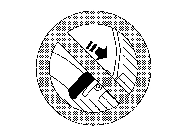
When working near the Air Bag Diagnosis Sensor Unit or other Air Bag System sensors with the ignition/power switch ON or engine running, never use air or electric power tools or strike near the sensor(s) with a hammer. Heavy vibration could activate the sensor(s) and deploy the air bag(s), possibly causing serious injury.
-
When using air or electric power tools or hammers, always switch the ignition/power switch OFF, disconnect the 12V battery or batteries, and wait at least 3 minutes before performing any service.
On Board Diagnostic (OBD) System of Engine and A/T
The ECM has an on board diagnostic system. It will illuminate the malfunction indicator lamp (MIL) to warn the driver of a malfunction causing emission deterioration.
CAUTION:
-
Always turn the ignition switch OFF and disconnect the negative battery cable before any repair or inspection work. The open/short circuit of related switches, sensors, solenoid valves, etc. will cause the MIL to illuminate.
-
Always connect and lock the connectors securely after work. A loose (unlocked) connector will cause the MIL to illuminate due to the open circuit. (Be sure the connector is free from water, grease, dirt, bent terminals, etc.)
-
Certain systems and components, especially those related to OBD, may use a new style slide-locking type harness connector. For description and how to disconnect, refer to Harness Connector.
-
Always route and secure the harnesses properly after work. The interference of the harness with a bracket, etc. may cause the MIL to illuminate due to the short circuit.
-
Always connect rubber tubes properly after work. A misconnected or disconnected rubber tube may cause the MIL to illuminate due to the malfunction of the EVAP system or fuel injection system, etc.
-
Always erase the unnecessary malfunction information (repairs completed) from the ECM and TCM (Transmission control module) before returning the Nissan Pathfinder vehicle to the customer.
General Precautions
-
Always use a 12 volt battery as power source.
-
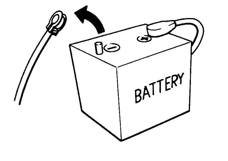
Never attempt to disconnect battery cables while engine is running.
-
Before connecting or disconnecting the ECM harness connector, turn ignition switch OFF and disconnect negative battery cable. Failure to do so may damage the ECM because battery voltage is applied to ECM even if ignition switch is turned OFF.
-
Before removing parts, turn ignition switch OFF and then disconnect negative battery cable.
-
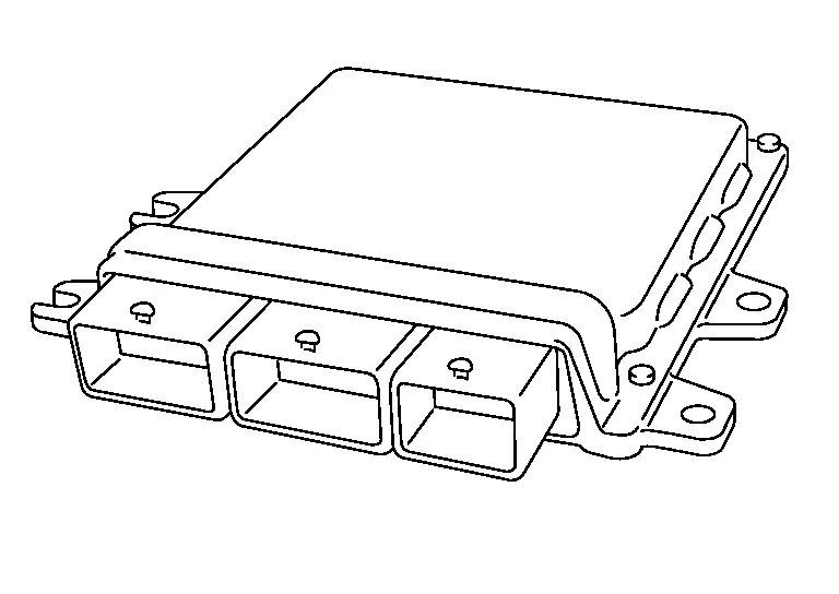
Never disassemble ECM.
-
If a battery cable is disconnected, the memory will return to the ECM value.
The ECM will now start to self-control at its initial value. Thus, engine operation can vary slightly in this case. However, this is not an indication of a malfunction. Never replace parts because of a slight variation.
-
If the battery is disconnected, the following emission-related diagnostic information will be cleared within 24 hours.
-
Diagnostic trouble codes
-
1st trip diagnostic trouble codes
-
Freeze frame data
-
1st trip freeze frame data
-
System readiness test (SRT) codes
-
Test values
-
-
When connecting or disconnecting pin connectors into or from ECM, never damage pin terminals (bends or break).
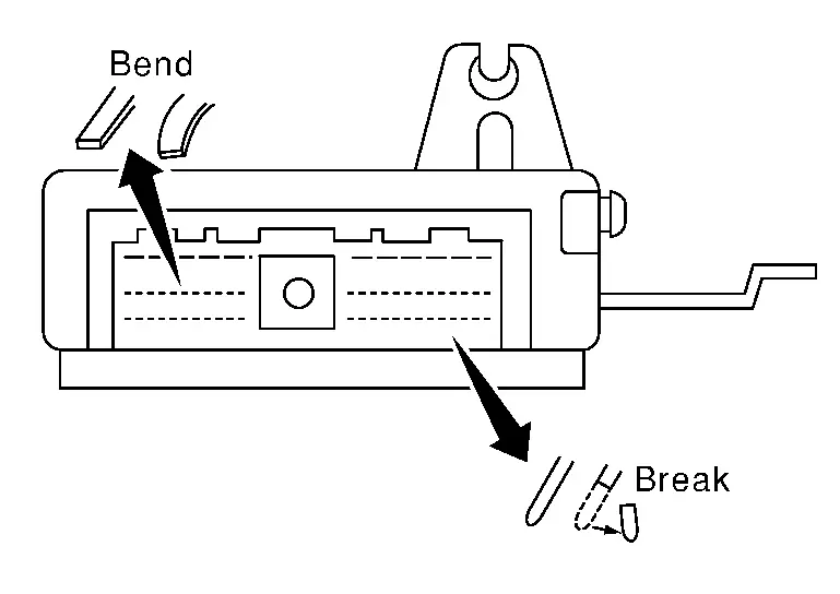
Make sure that there are not any bends or breaks on ECM pin terminal, when connecting pin connectors.
-
Securely connect ECM harness connectors.
A poor connection can cause an extremely high (surge) voltage to develop in coil and condenser, thus resulting in damage to ICs.
-
Keep engine control system harness at least 10 cm (4 in) away from adjacent harness, to prevent engine control system malfunctions due to receiving external noise, degraded operation of ICs, etc.
-
Keep engine control system parts and harness dry.
-
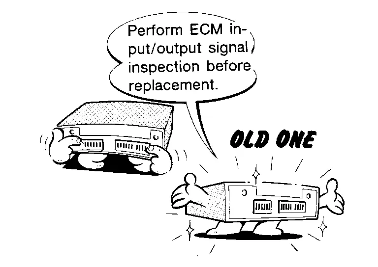
Before replacing ECM, perform ECM Terminals and Reference Value inspection and make sure ECM functions properly. Refer to Reference Value.
-
Handle mass air flow sensor carefully to avoid damage.
-
Never clean mass air flow sensor with any type of detergent.
-
Never disassemble electric throttle control actuator.
-
Even a slight leak in the air intake system can cause serious incidents.
-
Never shock or jar the camshaft position sensor, crankshaft position sensor.
-
After performing each TROUBLE DIAGNOSIS, perform DTC Confirmation Procedure or Component Function Check.
The DTC should not be displayed in the DTC Confirmation Procedure if the repair is completed. The Component Function Check should be a good result if the repair is completed.
-
When measuring ECM signals with a circuit tester, never allow the two tester probes to contact.
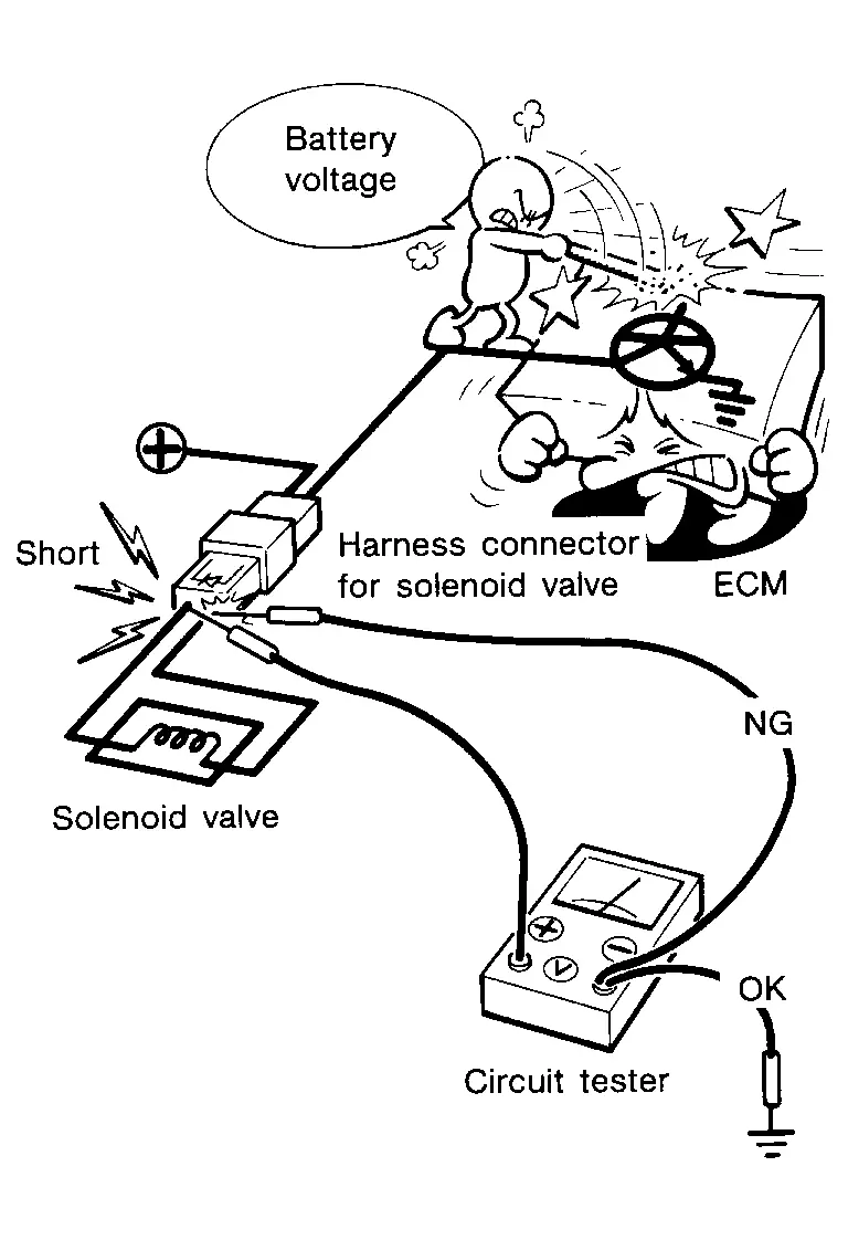
Accidental contact of probes will cause a short circuit and damage the ECM power transistor.
-
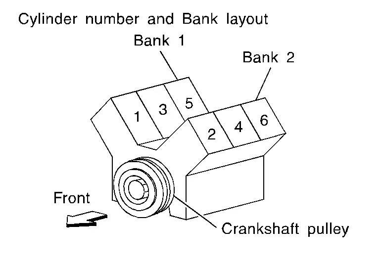
B1 indicates bank 1, B2 indicates bank 2 as shown in the figure.
-
Never operate fuel pump when there is no fuel in lines.
-
Tighten fuel hose clamps to the specified torque.
-
Never depress accelerator pedal when starting.
-
Immediately after starting, never rev up engine unnecessarily.
-
Never rev up engine just prior to shutdown.
-
When installing C.B. ham radio or a mobile phone, be sure to observe the following as it may adversely affect electronic control systems depending on installation location.
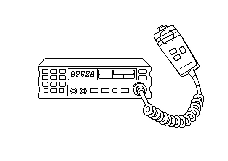
-
Keep the antenna as far as possible from the electronic control units.
-
Keep the antenna feeder line more than 20 cm (8 in) away from the harness of electronic controls.
Never let them run parallel for a long distance.
-
Adjust the antenna and feeder line so that the standing-wave ratio can be kept smaller.
-
Be sure to ground the radio to Nissan Pathfinder vehicle body.
-
Preparation Nissan Pathfinder 2022
Special Service Tools
 NOTE:
NOTE:
The actual shapes of TechMate tools may differ from those of special service tools illustrated here.
|
Tool number (TechMate No.) Tool name | Description | |
|---|---|---|
|
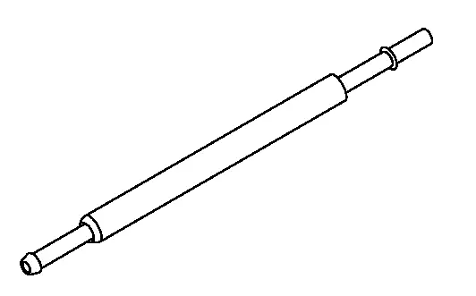
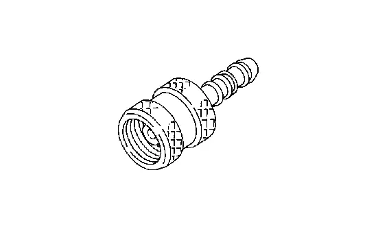
KV10120000 (-) Fuel tube adapter |
|
Measuring fuel pressure |
Commercial Service Tools
|
Tool name (TechMate No.) | Description | |
|---|---|---|
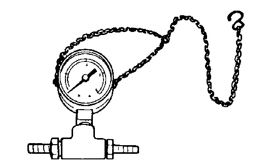
| Pressure gauge |
|
Checking fuel pressure
Use the pressure gauge which can measure 690 kpa (6.9 bar, 7.0kg/cm2, 100 psi) or more. |
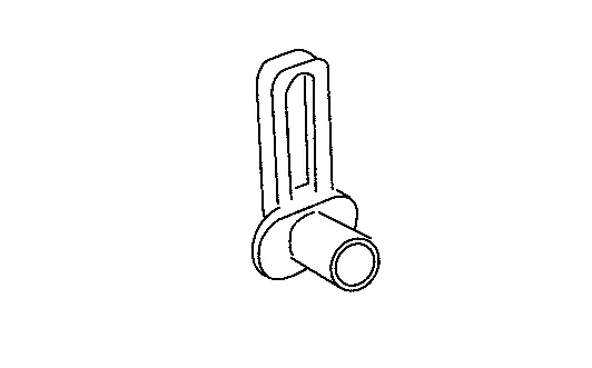
| Quick connector release |
|
Removing fuel tube quick connectors in engine room (Available in SEC. 164 of PARTS CATALOG: Parts No. 16441 6N210) |
|
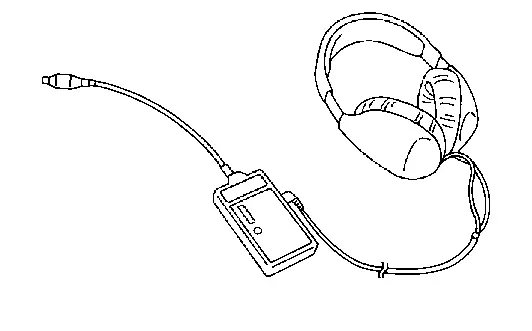
Leak detector i.e.: (NI-41416) |
|
Locates the EVAP leak |
|
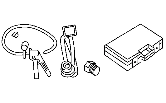
EVAP service port adapter i.e.: (NI-41413-OBD) |
|
Applies positive pressure through EVAP service port |
|
Fuel filler cap adapter i.e.: (NI-42909) |
|
Checks fuel tank vacuum relief valve opening pressure |
 NOTE:
NOTE:
Service Data and Specifications (SDS) Nissan Pathfinder 2022
Idle Speed
| Condition | Specification |
|---|---|
| No load* (in P or N position) | 650 ± 50 rpm |
*: Under the following conditions
-
A/C switch: OFF
-
Electric load: OFF (Lights, heater fan & rear window defogger)
-
Steering wheel: Kept in straight-ahead position
Ignition Timing
| Condition | Specification |
|---|---|
| No load* (in P or N position) | 14 ± 2° BTDC |
*: Under the following conditions
-
A/C switch: OFF
-
Electric load: OFF (Lights, heater fan & rear window defogger)
-
Steering wheel: Kept in straight-ahead position
Calculated Load Value
| Condition | Specification (Using CONSULT or GST) |
|---|---|
| At idle | 5 – 35 % |
| At 2,500 rpm | 5 – 35 % |
Mass Air Flow Sensor
| Supply voltage | Approx. 5 V |
| Output frequency at idle | 4,800 – 5,300 Hz* |
| Mass air flow (Using CONSULT or GST) |
1.8 – 3.2 g/s at idle* 7.7 – 14.3 g/s at 2,500 rpm* |
*: Engine is warmed up to normal operating temperature and running under no load.

Nissan Pathfinder (R53) 2022-2026 Service Manual
Vq35dd
Contact Us
Nissan Pathfinder Info Center
Email: info@nipathfinder.com
Phone: +1 (800) 123-4567
Address: 123 Pathfinder Blvd, Nashville, TN 37214, USA
Working Hours: Mon–Fri, 9:00 AM – 5:00 PM (EST)
