Nissan Pathfinder: Audio, Visual & Navigation System - Telematics System
Precautions Nissan Pathfinder 2026
Precaution for Supplemental Restraint System (SRS) "AIR BAG" and "SEAT BELT PRE-TENSIONER"
The Supplemental Restraint System such as “AIR BAG” and “SEAT BELT PRE-TENSIONER”, used along with a front seat belt, helps to reduce the risk or severity of injury to the driver and front passenger for certain types of collisions.
Information necessary to service the system safely is included in the “SRS AIR BAG” and “SEAT BELT” sections of this Service Manual.
WARNING:
Always observe the following items for preventing accidental activation:
-
To avoid rendering the SRS inoperative, which could increase the risk of personal injury or death in the event of a collision that would result in air bag inflation, it is recommended that all maintenance and repair be performed by an authorized NISSAN/INFINITI dealer.
-
Improper repair, including incorrect removal and installation of the SRS, can lead to personal injury caused by unintentional activation of the system. For removal of Spiral Cable and Air Bag Module, see “SRS AIR BAG”.
-
Never use electrical test equipment on any circuit related to the SRS unless instructed to in this Service Manual. SRS wiring harnesses can be identified by yellow and/or orange harnesses or harness connectors.
PRECAUTIONS WHEN USING POWER TOOLS (AIR OR ELECTRIC) AND HAMMERS
WARNING:
Always observe the following items for preventing accidental activation:
-
When working near the Air Bag Diagnosis Sensor Unit or other Air Bag System sensors with the ignition/power switch ON or engine running, never use air or electric power tools or strike near the sensor(s) with a hammer. Heavy vibration could activate the sensor(s) and deploy the air bag(s), possibly causing serious injury.
-
When using air or electric power tools or hammers, always switch the ignition/power switch OFF, disconnect the 12V battery or batteries, and wait at least 3 minutes before performing any service.
Precaution for Trouble Diagnosis
AV COMMUNICATION SYSTEM
-
Do not apply voltage of 7.0 V or higher to the measurement terminals.
-
Use the tester with its open terminal voltage being 7.0 V or less.
-
Be sure to turn ignition switch OFF and disconnect the battery cable from the negative terminal before checking the circuit.
Precaution for Harness Repair
AV COMMUNICATION SYSTEM
-
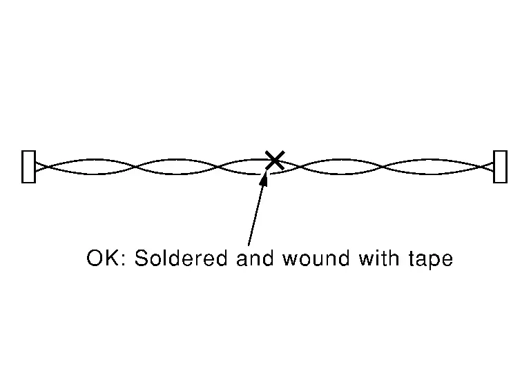
Solder the repaired parts, and wrap with tape. [Frays of twisted line must be within 110 mm (4.33 in).]
-
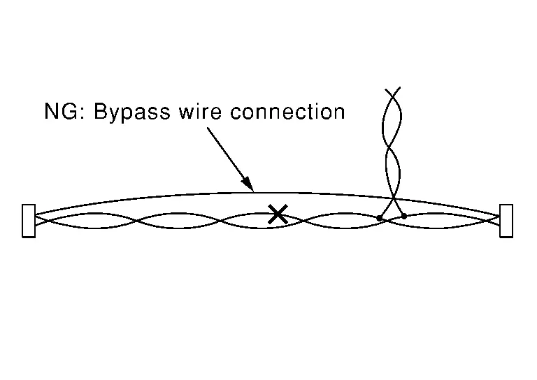
Do not perform bypass wire connections for the repair parts. (The spliced wire will become separated and the characteristics of twisted line will be lost.)
Precautions for Work
-
When removing or disassembling each component, be careful not to damage or deform it. If a component may be subject to interference, be sure to protect it with a shop cloth.
-
When removing (disengaging) components with a screwdriver or similar tool, be sure to wrap the component with a shop cloth or vinyl tape to protect it.
-
Protect the removed parts with a shop cloth and prevent them from being dropped.
-
Replace a deformed or damaged clip.
-
If a part is specified as a non-reusable part, always replace it with a new one.
-
Be sure to tighten bolts and nuts securely to the specified torque.
-
After installation is complete, be sure to check that each part works properly.
-
Follow the steps below to clean components:
-
Water soluble dirt:
-
Dip a soft cloth into lukewarm water, wring the water out of the cloth and wipe the dirty area.
-
Then rub with a soft, dry cloth.
-
-
Oily dirt:
-
Dip a soft cloth into lukewarm water with mild detergent (concentration: within 2 to 3%) and wipe the dirty area.
-
Then dip a cloth into fresh water, wring the water out of the cloth and wipe the detergent off.
-
Then rub with a soft, dry cloth.
-
-
Do not use organic solvent such as thinner, benzene, alcohol or gasoline.
-
For genuine leather seats, use a genuine leather seat cleaner.
-
Preparation Nissan Pathfinder R53
Special Service Tools
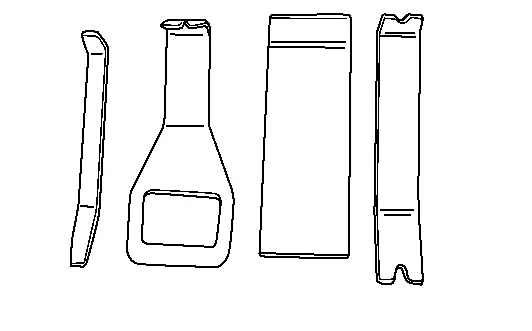
The actual shape of the tools may differ from those illustrated here.
|
Tool number (TechMate No.) Tool name | Description | |
|---|---|---|
|
— (NI-46534) Trim Tool Set |
|
Removing trim components |
|
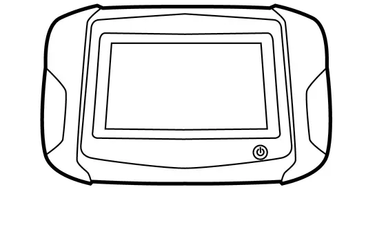
— (NI-51922) Enhanced Multi-Media Interface Tester (EMMIT) |
|
Tests the functionality of the following features: Bluetooth
USB
AUX
|
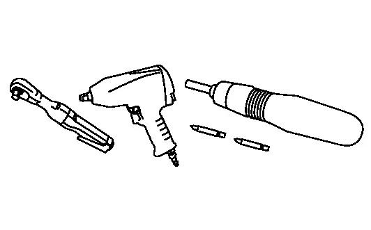
Commercial Service Tools
| Tool name | Description | |
|---|---|---|
| Power tool |
|
Loosening nuts, screws and bolts |
Ecu Diagnosis Information. Tcu Nissan Pathfinder 2022
Values on the Diagnosis Tool
 NOTE:
NOTE:
The following table includes information (items) inapplicable to this Nissan Pathfinder vehicle. For information (items) applicable to this vehicle, refer to CONSULT display items.
| Monitor Item | Condition | Value/Status | |
|---|---|---|---|
| USB | Ignition switch ON | External device connects to USB connector | Con |
| External device not connected to USB connector | No con | ||
| SIM status |
This item is displayed, but cannot be used. |
Unlock | |
| Backup battery age | Ignition switch ON | Display backup battery age (days) | |
| eUICC STATUS PIN used |
This item is displayed, but cannot be used. |
Enable | |
| SOS switch | Ignition switch ON | When pressing SOS switch | On |
| Except for above | Off | ||
| Radio wave | Ignition switch ON | On | |
| Zone | Ignition switch ON | U.S.A | |
| Power type | Ignition switch ON | Engine | |
| Brand | Ignition switch ON | Nissan | |
 NOTE:
NOTE:
 NOTE:
NOTE:
Reference Value
TERMINAL LAYOUT
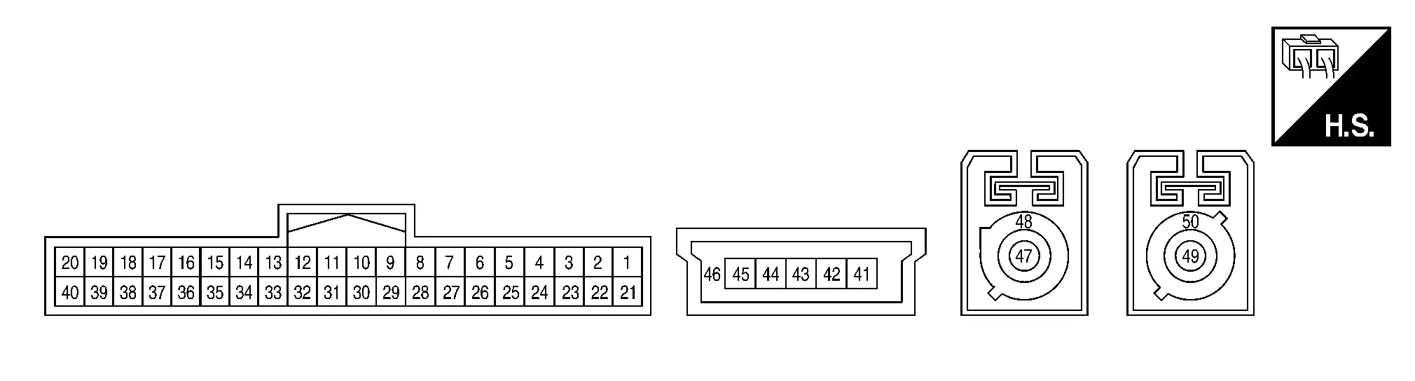
PHYSICAL VALUES
|
Terminal (Wire color) | Description | Condition |
Reference value (Approx.) | ||
|---|---|---|---|---|---|
| + | – | Signal name | Input/Output | ||
|
1 (L) |
29 (B) |
Battery power supply | Input | Ignition switch OFF | Battery Voltage |
|
5 (W) |
28 (B) |
SOS switch LED signal | Input |
Ignition switch ACC
|
0 V |
|
Ignition switch ACC
|
5 V | ||||
|
6 (SB) |
— | CAN-High | Input/Output | — | — |
|
7 (V) |
— | CAN-Low | Input/Output | — | — |
|
12 (B) |
28 (B) |
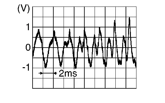
Microphone signal | Output |
Ignition switch ON
|
|
|
17 (W) |
28 (B) |
Microphone signal | Input |
Ignition switch ON
|
|
|
18 (B) |
28 (B) |
Microphone VCC | Input | Ignition switch ON | 5 V |
|
26 (SB) |
— | AV communication high | Input/Output | — | — |
|
27 (LG) |
— | AV communication low | Input/Output | — | — |
|
28 (B) |
Ground | Ground | — | Ignition switch ON | 0 V |
|
29 (B) |
Ground | Ground | — | Ignition switch ON | 0 V |
|
31 (W) |
32 (B) |
Sound signal (+) | Output |
Ignition switch ON
|
|
|
37 (R) |
28 (B) |
SOS call switch signal | Input |
Ignition switch ON
|
0 V |
|
Ignition switch ON
|
5 V | ||||
|
41 (B) |
— | Ground | — | — | — |
|
43 (G) |
— | D+ signal | Input/Output | — | — |
|
44 (W) |
— | D- signal | Input/Output | — | — |
|
45 (R) |
— | V BUS signal | Input | — | — |
|
46 (Shield) |
— | Shield | — | — | — |
|
47 (B) |
Ground | TEL antenna signal | Input | TEL antenna connector disconnected | 2.8 V |
|
48 (Shield) |
— | Shield | — | — | — |
|
49 (B) |
Ground | GPS antenna signal | Input | GPS antenna connector disconnected | 2.8 V |
|
50 (Shield) |
— | Shield | — | — | — |


Fail-safe
If a malfunction occurs in the telematics system, TCU performs fail-safe activation according to the detected malfunction.
| DTC | Telematics operation in fail-safe mode |
|---|---|
| B2E01-16 | Telematics system does not operate |
| B2E01-4A | |
| B2E01-4B | |
| B2E01-96 | |
| B2E04-16 | |
| B2E05-29 | |
| B2E08-01 | Microphone does not operate |
| B2E0B-01 | Telematics system does not operate |
| B2E0F-06 | Remote function does not operate |
| B2E12-55 | TCU has not been initialized |
| B2E1B-06 | Telematics system does not operate |
| B2E1B-97 | Automatic emergency call does not operate |
| B2E32-11 | Telematics sound is not output |
| B2E32-12 | |
| B2E32-13 | |
| B2E34-11 | Telematics can not send and receive via network |
| B2E34-12 | |
| B2E34-13 | |
| B2E35-11 | Telematics can not send correct position |
| B2E35-12 | |
| B2E35-13 | |
| B2E49-06 | Remote function does not operate |
| B2E4C-06 | |
| B2E4F-08 | Remote engine start functions cannot be used |
| U0074-00 | Telematics system does not operate |
| U0079-00 |
DTC Inspection Priority Chart
If multiple DTCs are detected simultaneously, check them one by one depending on the following DTC inspection priority chart:
| Priority | Detected items (DTC) |
|---|---|
| 1 |
|
| 2 |
|
| 3 |
|
| 4 |
|
DTC Index
| CONSULT Display | Reference Page |
|---|---|
| B2E01-4A: Internal battery | DTC Description |
| B2E01-4B: Internal battery | |
| B2E01-16: Internal battery | |
| B2E01-96: Internal battery | |
| B2E04-16: Internal battery | DTC Description |
| B2E05-29: Air Bag | DTC Description |
| B2E08-01: Microphone | DTC Description |
| B2E0B-01: SOS LED (Auto) | DTC Description |
| B2E0F-06: GPS antenna | DTC Description |
| B2E12-55: Configuration | DTC Description |
| B2E1B-06: Automatic eCall Locked | DTC Description |
| B2E1B-97: Automatic eCall Locked | |
| B2E32-11: Audio unit | DTC Description |
| B2E32-12: Audio unit | |
| B2E32-13: Audio unit | |
| B2E34-11: TEL antenna | DTC Description |
| B2E34-12: TEL antenna | |
| B2E34-13: TEL antenna | |
| B2E35-11: GPS antenna | DTC Description |
| B2E35-12: GPS antenna | |
| B2E35-13: GPS antenna | |
| B2E49-06: Remote actuator not activated | DTC Description |
| B2E4C-06: Remote actuator without unknown ID | DTC Description |
| B2E4F-08: BCM pairing | DTC Description |
| U0074-00: AV communication | DTC Description |
| U0079-00: CAN communication | DTC Description |

Nissan Pathfinder (R53) 2022-2026 Service Manual
Telematics System
Contact Us
Nissan Pathfinder Info Center
Email: info@nipathfinder.com
Phone: +1 (800) 123-4567
Address: 123 Pathfinder Blvd, Nashville, TN 37214, USA
Working Hours: Mon–Fri, 9:00 AM – 5:00 PM (EST)
