Nissan Pathfinder: Mirrors - System
Door Mirror System Nissan Pathfinder 2026
System Description
SYSTEM DIAGRAM
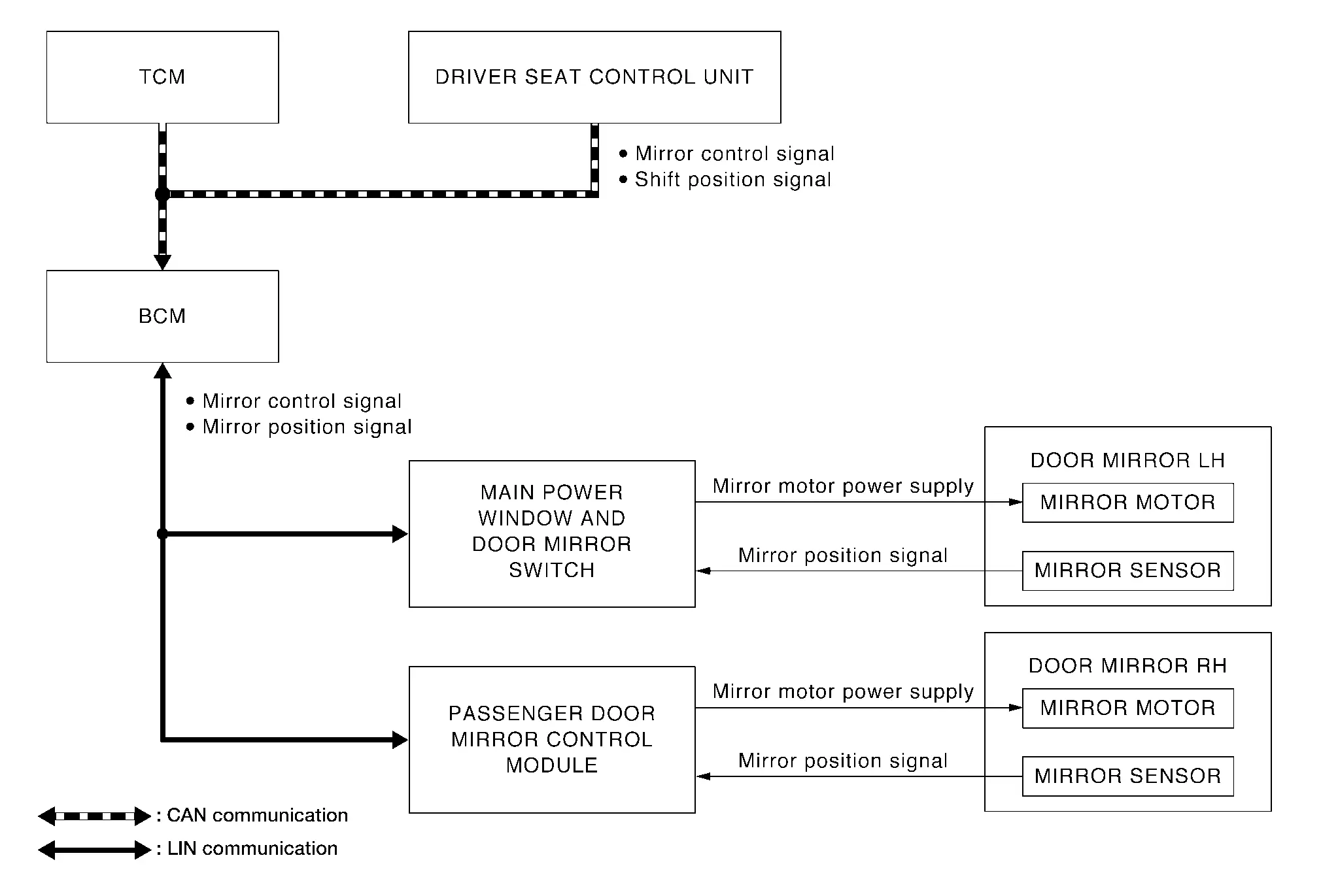
INPUT/OUTPUT SIGNAL CHART
| Input | Input signal to BCM | BCM function | Output |
|---|---|---|---|
| Main power window and door mirror switch | Mirror position signal | Transmits the mirror control signal and mirror position signal | Door mirror motors |
| Passenger door mirror control module | |||
| Driver seat control unit1 | Mirror control signal | ||
| TCM | Shift position signal |
1: with Automatic Drive Positioner
MANUAL OPERATION
Description
-
Main power window and door mirror switch inputs mirror control signal and perform the LH/RH control of door mirror motor supplying electric power when changeover switch is operated.
-
Main power window and door mirror switch inputs mirror control signal and supplies electric power to door mirror.
Operation Conditions
If the following conditions are not satisfied, operation is not performed.
-
Ignition switch: ON
-
Changeover switch: Select either left or right
AUTOMATIC DRIVE POSITIONER LINKED OPERATION (IF EQUIPPED)
Door mirror control is included in automatic drive positioner system. Refer to automatic drive positioner system for more details. Refer to System Description.
REVERSE INTERLOCK DOOR MIRROR FUNCTION
Description
-
Select either of the door mirror faces by changeover switch, and then set mirror face downward.
-
When ignition switch is ON position and electric shift selector is in R position, TCM sends the R signal to BCM.
-
The mirror control signal is transmitted to Main power window and door mirror switch and passenger door mirror control module from BCM via LIN communication.
-
When the mirror control signal is detected, Main power window and door mirror switch and passenger door mirror control module activated mirror motor.
Operation Conditions
If the following conditions are not satisfied, operation is not performed.
-
Ignition switch: ON
-
Electric shift selector: R position
-
Change over switch: Select either left or right
 NOTE:
NOTE:
During the reverse interlock door mirror system, if all of the above conditions are not satisfied, mirror face returns to original angle.
Smart Rear View Mirror System Nissan Pathfinder Fifth generation
System Description
SYSTEM DIAGRAM
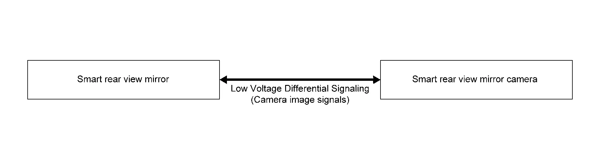
SYSTEM DESCRIPTION
Smart Rear View Mirror has the following functions:
-
When the power lever located at the bottom of the Smart Rear View Mirror is turned ON, the image from the Smart Rear View Mirror camera is displayed on the LCD monitor integrated in the Smart Rear View Mirror. When turned OFF, it returns to the normal rear view mirror mode.
-
Camera image signals are communicated between the Smart Rear View Mirror and the Smart Rear View Mirror camera by LVDS (Low Voltage Differential Signaling).
Smart Rear View Mirror operational condition of the following items:
-
Ignition: ON or START
-
Smart Rear View Mirror power supply: ON

Nissan Pathfinder (R53) 2022-2026 Service Manual
System
Contact Us
Nissan Pathfinder Info Center
Email: info@nipathfinder.com
Phone: +1 (800) 123-4567
Address: 123 Pathfinder Blvd, Nashville, TN 37214, USA
Working Hours: Mon–Fri, 9:00 AM – 5:00 PM (EST)
