Nissan Pathfinder: Sonar System - System Description
Component Parts. Sonar System Nissan Pathfinder 2026
Component Parts Location
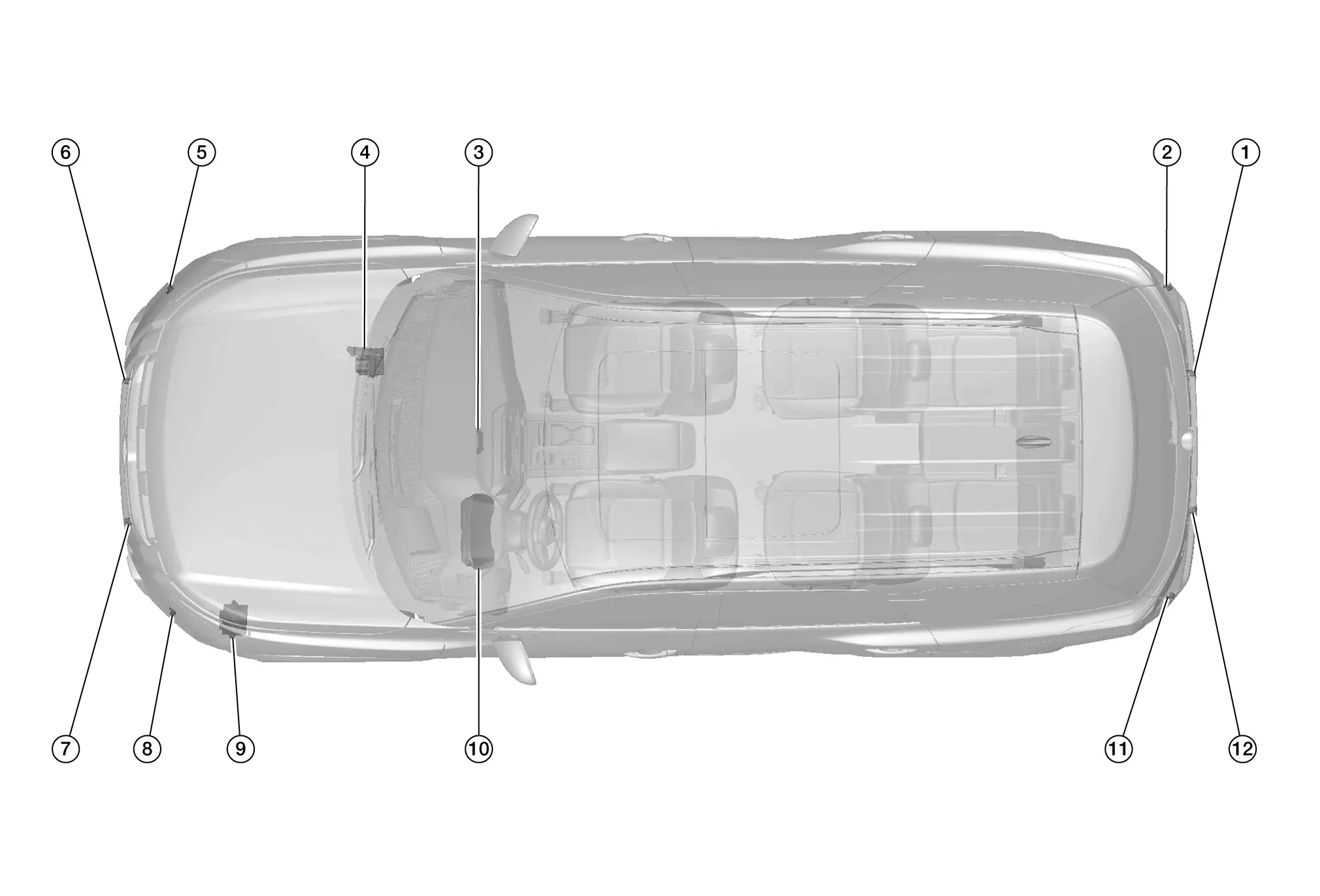
| No. | Component | Function |
|---|---|---|
| 1. | Rear sonar sensor RH inner | Refer to Sonar Sensor. |
| 2. | Rear sonar sensor RH outer | |
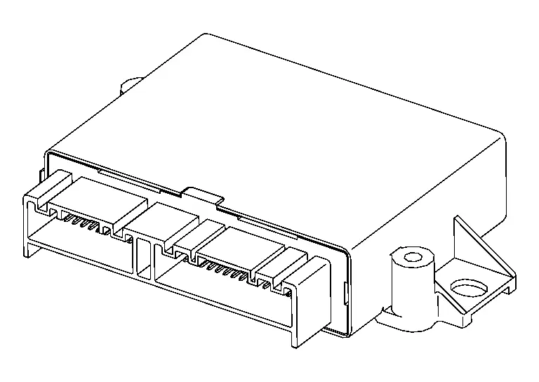
| 3. | Sonar control unit | Refer to Sonar Control Unit. |
| 4. | ABS (Anti-lock Braking System) actuator and electric unit (control unit) | Provides the sonar control unit with the Nissan Pathfinder vehicle speed signal via CAN communication. |
| 5. | Front sonar sensor RH outer (with front sonar system) | Refer to Sonar Sensor. |
| 6. | Front sonar sensor RH inner (with front sonar system) | |
| 7. | Front sonar sensor LH inner (with front sonar system) | |
| 8. | Front sonar sensor LH outer (with front sonar system) | |
| 9. | TCM (Transmission Control Module) | Provides the sonar control unit with the shift position signal via CAN communication. |
| 10. | Combination meter | Provides the sonar control unit with the system selection signal via CAN communication. |
| 11. | Rear sonar sensor LH outer | Refer to Sonar Sensor. |
| 12. | Rear sonar sensor LH inner |
Sonar Control Unit
-
Sonar control unit is installed behind the front A/C switch assembly.
-
For Nissan Pathfinder vehicles with around view monitor system, sonar sensor signals are received by the sonar control unit and transmitted to the around view monitor control unit and combination meter via CAN communication for the indicator display.
-
For Nissan Pathfinder vehicles with rear view monitor system, Sonar sensor signals are received by the sonar control unit and transmitted to the AV control unit and combination meter via CAN communication for the indicator display.
-
Sonar control unit outputs a buzzer signal to the AV control unit via CAN communication for the audible alert.
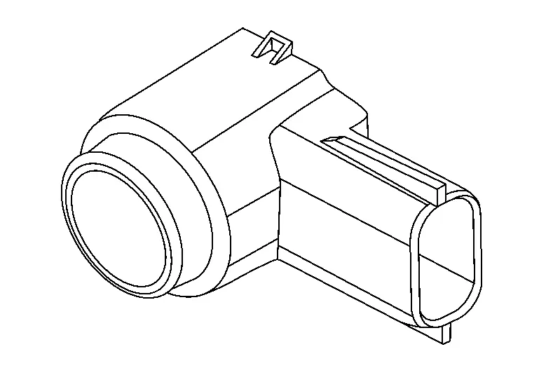
Sonar Sensor
-
The sonar sensors are installed in the front bumper and rear bumper fascias.
-
When a distance from an obstacle is detected, a signal is transmitted to the sonar control unit.
System Nissan Pathfinder 2026
System Description
SYSTEM DIAGRAM
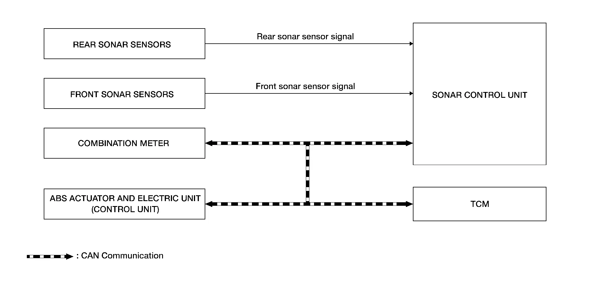
Sonar Control Unit Input Signal (CAN Communication)
| Transmit unit | Signal name |
|---|---|
| Combination meter | System selection signal |
| ABS actuator and electric unit (control unit) | Nissan Pathfinder Vehicle speed signal |
| TCM | Shift position signal |
DESCRIPTION
-
The sonar sensors installed on the front (with front sonar system) and rear bumpers detect obstacles around the bumper.
-
The sonar control unit changes the buzzer cycle and warning indicator according to the distance from an obstacle detected by the sonar sensors.
SONAR SYSTEM ACTIVATION CONDITION
The sonar system warns the driver of the presence of obstacles when the following conditions are met:
×: Activation
| Shift position | Nissan Pathfinder Vehicle speed (Approx.) | Obstacle detecting sensor | Buzzer | Sonar indicator |
|---|---|---|---|---|
| R | 6.21MPH (10 km/h) or less | Front sensor | × | × |
| Rear sensor | × | × | ||
| D | 6.21MPH (10 km/h) or less | Front sensor | × | × |
| Rear sensor | — | — |
OBSTACLE DETECTION DISTANCE
Warning Buzzer Frequency
-
The warning buzzer output frequency changes in 4 levels according to the detection distance.
-
As the Nissan Pathfinder vehicle approaches an obstacle, the buzzer-sounding cycle becomes shorter.
-
Rear Sonar
Obstacle detection range image
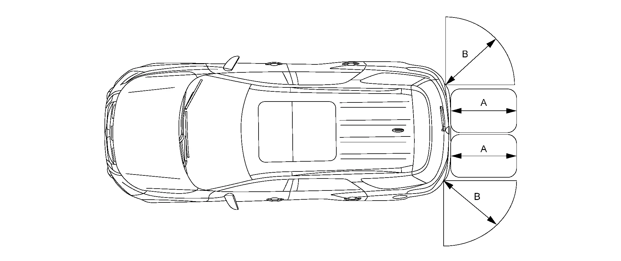
A. Approx. 59.06 in (150 cm)
(default value)B. Approx. 23.62 in (60 cm)
(default value) -
Front and Rear Sonar
Obstacle detection range image
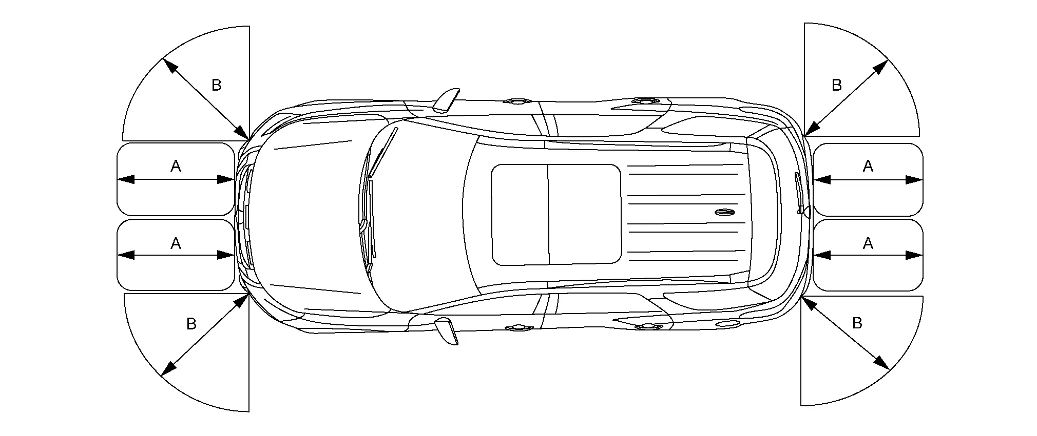
A. Approx. 47.24 in (120 cm)
(default value)B. Approx. 23.62 in (60 cm)
(default value)
| Detection distance | Warning buzzer frequency |
|---|---|
|
11.81 - 13.78 in (30 - 35 cm) |
10.0 Hz |
|
13.78 - 19.69 in (35 - 50 cm) |
9.0 Hz |
|
19.69 - 27.56 in (50 - 70 cm) |
6.66 Hz |
|
27.56 - 35.43 in (70 - 90 cm) |
5.0 Hz |
|
35.43 - 47.24 in (90 - 120 cm) |
4.0 Hz |
|
47.24 - 59.06 in (120 - 150 cm) |
3.0 Hz |
|
59.06 - 70.87 in (150 - 180 cm) |
2.5 Hz |
|
70.87 in or more (180 cm or more) |
2.0 Hz |
-
Detection distance of an obstacle changes as shown in the table below:
Detection distance Item (detection range) Outer sensor Side sensor Front inner sensor Rear inner sensor FAR Approx. 25.98 in (66 cm) Approx. 25.98 in (66 cm) Approx. 43.31 in (110 cm) Approx. 64.96 in (165 cm) NORMAL (default value) Approx. 23.62 in (60 cm) Approx. 23.62 in (60 cm) Approx. 39.37 in (100 cm) Approx. 59.06 in (150 cm) NEAR Approx. 21.26 in (54 cm) Approx. 21.26 in (54 cm) Approx. 35.43 in (90 cm) Approx. 53.15 in (135 cm)
Sonar Indicator
-
The sonar indicator displays in three stages (green, yellow, and red), according to the distance from an obstacle.
-
Sonar indicator distance display changes according to the following table:
Status of warning Detection distance Outer sensor Front inner sensor Rear inner sensor Red 0 - 11.81 in
(0 - 30 cm)0 - 11.81 in
(0 - 30 cm)0 - 11.81 in
(0 - 30 cm)Yellow 12.2 - 19.69 in
(31 - 50 cm)12.2 - 23.62 in
(31 - 60 cm)12.2 - 23.62 in
(31 - 60 cm)Green 20.08 - 23.62 in
(51 - 60 cm)24.02 - 39.37 in
(61 - 100 cm)24.02 - 59.06 in
(61 - 150 cm)
MAC(Message Authentication Code)
MAC (Message Authentication Code) is a function that prevents unauthorized communication by using secure authentication communication. Sonar control unit writes a MAC key required for communication between ECUs and performs MAC diagnosis.
Diagnosis System (sonar Control Unit) Nissan Pathfinder Fifth generation
CONSULT Function
APPLICATION ITEMS
CONSULT can display each diagnostic item using the diagnostic test modes shown:
| Direct Diagnostic Mode | Description |
|---|---|
| Self Diagnostic Result | The sonar control unit self diagnostic results are displayed. |
| Data Monitor | The sonar control unit input/output data is displayed in real time. |
| Work support | The settings for sonar control unit functions can be changed. |
| ECU Identification | The sonar control unit part number is displayed. |
SELF-DIAGNOSTIC RESULTS
For details, refer to DTC Index .
Freeze Frame Data (FFD)
The following vehicle status is recorded when DTC is detected and is displayed on CONSULT.
| Item name | Display content |
|---|---|
|
ODO/TRIP METER (km) |
Total driving distance (odometer value) upon DTC detection is displayed. |
| DTC count | Records the number of times DTC was detected. |
DATA MONITOR
 NOTE:
NOTE:
The following table includes information (items) inapplicable to this Nissan Pathfinder vehicle. For information (items) applicable to this vehicle, refer to CONSULT display items.
| Monitor Item | Display/UNIT | Description |
|---|---|---|
| Continuous tone area | cm |
This item is displayed, but cannot be monitored. |
| Discontinuous tone area (near) | cm |
This item is displayed, but cannot be monitored. |
| Discontinuous tone area (far) 1 | cm |
This item is displayed, but cannot be monitored. |
| Discontinuous tone area (far) 2 | cm |
This item is displayed, but cannot be monitored. |
| Nissan Pathfinder Vehicle SPEED | km/h | Value of vehicle speed signal. |
| SONAR C/U POWER SUPPLY | V | Value of battery voltage (Ignition signal) |
| DETECTION MODE | MODE 1/MODE 2/MODE 3/MODE 4 |
This item is displayed, but cannot be monitored. |
| SHRT DST FRM RR SENS | cm | Display the closest distance detected by the rear sensor. |
| SHRT DST FRM FR SENS | cm | Display the closest distance detected by the front sensor. |
| COR[RL] | cm | Distance according to oscillation from rear sonar sensor LH outer and detection by rear sonar sensor LH outer. |
| COR[RL]->CEN[RL]/CEN[R] | cm | Distance according to oscillation from rear sonar sensor LH outer and detection by rear sonar sensor LH inner. |
| CEN[RL]/CEN[R]->COR[RL] | cm | Distance according to oscillation from rear sonar sensor LH inner and detection by rear sonar sensor LH outer. |
| CEN[RL]/CEN[R] | cm | Distance according to oscillation from rear sonar sensor LH inner and detection by rear sonar sensor LH inner. |
| CEN[RL]->CEN[RR] | cm | Distance according to oscillation from rear sonar sensor LH inner and detection by rear sonar sensor RH inner. |
| CEN[RR]->CEN[RL] | cm | Distance according to oscillation from rear sonar sensor RH inner and detection by rear sonar sensor LH inner. |
| CEN[RR] | cm | Distance according to oscillation from rear sonar sensor RH inner and detection by rear sonar sensor RH inner. |
| CEN[RR]/CEN[R]->COR[RR] | cm | Distance according to oscillation from rear sonar sensor RH inner and detection by rear sonar sensor RH outer. |
| COR[RR]->CEN[RR]/CEN[R] | cm | Distance according to oscillation from rear sonar sensor RH outer and detection by rear sonar sensor RH inner. |
| COR[RR] | cm | Distance according to oscillation from rear sonar sensor RH outer and detection by rear sonar sensor RH outer. |
| COR[FL] | cm | Distance according to oscillation from front sonar sensor LH outer and detection by front sonar sensor LH outer. |
| COR[FL]->CEN[FL]/CEN[F] | cm | Distance according to oscillation from front sonar sensor LH outer and detection by front sonar sensor LH inner. |
| CEN[FL]/CEN[F]->COR[FL] | cm | Distance according to oscillation from front sonar sensor LH inner and detection by front sonar sensor LH outer. |
| CEN[FL]/CEN[F] | cm | Distance according to oscillation from front sonar sensor LH inner and detection by front sonar sensor LH inner. |
| CEN[FL]->CEN[FR] | cm | Distance according to oscillation from front sonar sensor LH inner and detection by front sonar sensor RH inner. |
| CEN[FR]->CEN[FL] | cm | Distance according to oscillation from front sonar sensor RH inner and detection by front sonar sensor LH inner. |
| CEN[FR] | cm | Distance according to oscillation from front sonar sensor RH inner and detection by front sonar sensor RH inner. |
| CEN[FR]/CEN[F]->COR[FR] | cm | Distance according to oscillation from front sonar sensor RH inner and detection by front sonar sensor RH outer. |
| COR[FR]->CEN[FR]/CEN[F] | cm | Distance according to oscillation from front sonar sensor RH outer and detection by front sonar sensor RH inner. |
| COR[FR] | cm | Distance according to oscillation from front sonar sensor RH outer and detection by front sonar sensor RH outer. |
| RVRB TIME COR[RL] | ms |
This item is displayed, but cannot be monitored. |
| RVRB TIME COR[RR] | ms |
This item is displayed, but cannot be monitored. |
| RVRB TIME CEN[RL] | ms |
This item is displayed, but cannot be monitored. |
| RVRB TIME CEN[RR] | ms |
This item is displayed, but cannot be monitored. |
| RVRB TIME COR[FL] | ms |
This item is displayed, but cannot be monitored. |
| RVRB TIME COR[FR] | ms |
This item is displayed, but cannot be monitored. |
| RVRB TIME CEN[FL] | ms |
This item is displayed, but cannot be monitored. |
| RVRB TIME CEN[FR] | ms |
This item is displayed, but cannot be monitored. |
| REAR BUZZER | On/Off |
This item is displayed, but cannot be monitored. |
| LED | On/Off |
This item is displayed, but cannot be monitored. |
| Limit angle | deg |
This item is displayed, but cannot be monitored. |
| Driving corridor low angle | deg |
This item is displayed, but cannot be monitored. |
| Driving corridor high angle | deg |
This item is displayed, but cannot be monitored. |
| Timeout for scan zones | second |
This item is displayed, but cannot be monitored. |
 NOTE:
NOTE:
 NOTE:
NOTE:
 NOTE:
NOTE:
 NOTE:
NOTE:
 NOTE:
NOTE:
 NOTE:
NOTE:
 NOTE:
NOTE:
 NOTE:
NOTE:
 NOTE:
NOTE:
 NOTE:
NOTE:
 NOTE:
NOTE:
 NOTE:
NOTE:
 NOTE:
NOTE:
 NOTE:
NOTE:
 NOTE:
NOTE:
 NOTE:
NOTE:
 NOTE:
NOTE:
 NOTE:
NOTE:
 NOTE:
NOTE:
WORK SUPPORT
| Support Item | Setting | Description |
|---|---|---|
| VOLUME SETTING | Vol.1 | Allows you to set volume of warning tone. |
| Low | ||
| Vol.3 | ||
| Middle | ||
| Vol.5 | ||
| High | ||
| Off | ||
| MAC KEY writing | – | Write the MAC key to the sonar control unit. |
ECU IDENTIFICATION
Displays the part number of the sonar control unit.

Nissan Pathfinder (R53) 2022-2026 Service Manual
System Description
Contact Us
Nissan Pathfinder Info Center
Email: info@nipathfinder.com
Phone: +1 (800) 123-4567
Address: 123 Pathfinder Blvd, Nashville, TN 37214, USA
Working Hours: Mon–Fri, 9:00 AM – 5:00 PM (EST)
