Nissan Pathfinder: Automatic Drive Positioner - System Description
Component Parts. Automatic Drive Positioner System Nissan Pathfinder R53
Component Parts Location
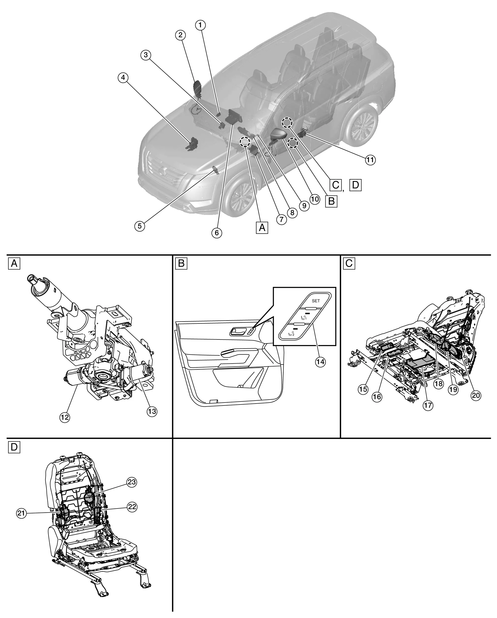
| A. | Bottom of steering column (view with steering column removed) | B. | Seat memory switch (view with front door finisher LH removed) | C. | Underside side of front LH seat (view with seat disassembled) |
| D. | Front side of front LH seat (view with seat disassembled) | ||||
| No. | Component | Function | |
|---|---|---|---|
| 1. | Passenger door mirror control module (if so equipped) |
Operates door mirror RH with the signal from the BCM. Refer to Component Parts Location for detailed component location. |
|
| 2. | Door mirror RH | Door mirror motor |
Makes mirror face operate from side to side and up and down with the electric power that passenger door mirror control unit supplies. Refer to Component Parts Location for detailed component location. |
| Mirror sensor |
|
||
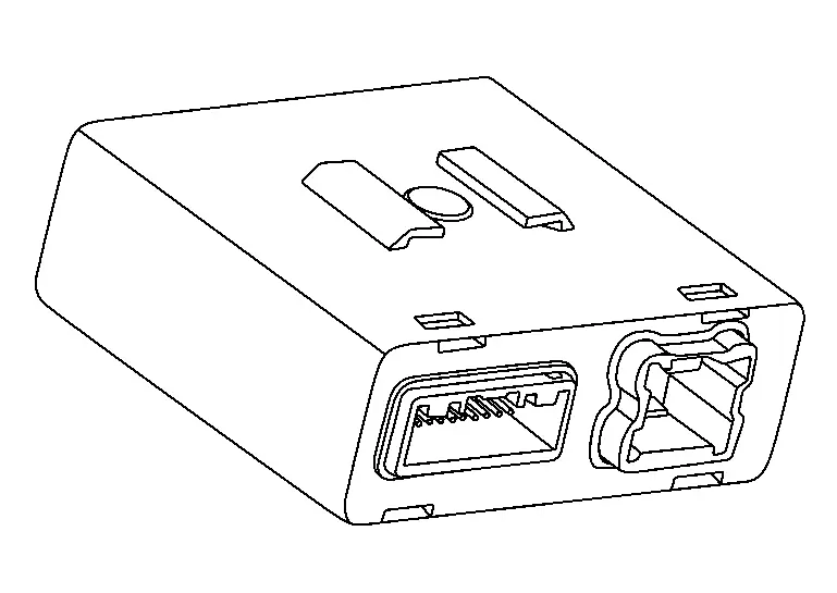
| 3. | Automatic drive positioner control unit (if so equipped) | Refer to Automatic Drive Positioner Control Unit. | |
| 4. | ABS (Anti-Lock Braking System) actuator and electric unit (control unit) |
Transmits the Nissan Pathfinder vehicle speed signal to driver seat control unit via CAN communication. Refer to Component Parts Location for detailed component location. |
|
| 5. | TCM (Transmission Control Module) |
Transmit the electric shift selector signal to driver seat control unit via CAN communication. Refer to Component Parts Location for detailed component location. |
|
| 6. | AV control unit |
Transmits the user information signal to driver seat control unit via CAN communication. Refer to Component Parts Location for detailed component location. |
|
| 7. | BCM (Body Control Module) |
Recognizes the following statuses and transmits them to driver seat control unit via CAN communication:
|
|
| 8. | Combination meter |
Transmits the Nissan Pathfinder vehicle speed signal to driver seat control unit via CAN communication. Refer to Component Part Location (Full TFT Meter) or Component Part Location (7 Inch Information Display Meter) for detailed component location. |
|
| 9. | ADP (Automatic Drive Positioner) steering switch (if so equipped) | Transmits the tilt/telescopic motor request signal to the automatic drive positioner control unit. | |
| 10. | Door mirror LH | Door mirror motor |
Makes mirror face operate from side to side and up and down with the electric power that main power window and door mirror switch supplies. Refer to Component Parts Location for detailed component location. |
| Mirror sensor |
|
||
| 11. | Front door lock assembly LH (door switch) |
Detects door open/close condition and transmits it to BCM. Refer to Component Parts Location for detailed component location. |
|
| 12. | Tilt motor (if so equipped) | Tilt motor |
|
| Tilt sensor |
|
||
| 13. | Telescopic motor (if so equipped) | Telescopic motor |
|
| Telescopic sensor |
|
||
| 14. | Seat memory switch | Refer to Seat Memory Switch. | |
| 15. | Lifting motor LH (front) | Lifting motor |
|
| Lifting sensor |
|
||
| 16. | Sliding motor LH | Sliding motor |
|
| Sliding sensor |
|
||
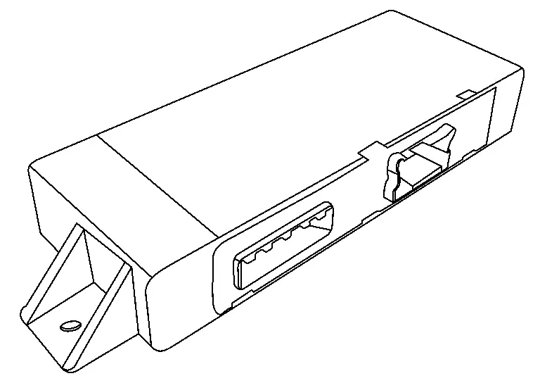
| 17. | Driver seat control unit | Refer to Driver Seat Control Unit. | |
| 18. | Power seat switch LH | Sliding switch |
|
| Reclining switch |
|
||
| Lifting switch (front) |
|
||
| Lifting switch (rear) |
|
||
| 19. | Lumbar support switch (with 4 way lumbar) (if so equipped) | Sends signal to driver seat control unit for lumbar support motor via CAN communication. | |
| 20. | Lifting motor LH (rear) | Lifting motor |
|
| Lifting sensor |
|
||
| 21. | Lumbar support motor Y (with 4 way lumbar) (if so equipped) | Lumbar support motor |
|
| Lumbar sensor |
|
||
| 22. | Reclining motor LH | Reclining motor |
|
| Reclining sensor |
|
||
| 23. | Lumbar support motor X (with 4 way lumbar) (if so equipped) | Lumbar support motor |
|
| Lumbar sensor |
|
||
Automatic Drive Positioner Control Unit
-
It communicates with driver seat control unit via CAN communication.
-
Performs various controls with the instructions of driver seat control unit.
-
Performs the controls of the tilt and telescopic motors.
-
Operates door mirror LH with the signal from the driver seat control unit.
-
Automatic drive positioner control unit is located behind the center of the instrument panel.
Driver Seat Control Unit
-
Main unit of automatic drive positioner system.
-
It is connected to the CAN communication system.
-
Operates each motor of seat to the registered position.
-
Performs the control of seat memory switch.
-
Operates the specific seat motor with the signal from power seat switch LH.
-
Driver seat control module is installed to the bottom of the front LH seat assembly.
Seat Memory Switch
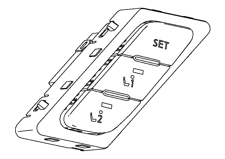
SET SWITCH
It is used for registration and setting change of driving position.
SEAT MEMORY SWITCH
-
Seat memory switch is located on the front door finisher LH.
-
The maximum 2 driving positions can be registered by memory switch 1 to 2.
-
Driving position is set to the registered driving position when memory switch is pressed while operation conditions are satisfied.
SEAT MEMORY INDICATOR
Memory indicator indicates the status of automatic drive positioner system by turning ON or blinking.
Diagnosis System (driver Seat Control Unit) Nissan Pathfinder
CONSULT Function (AUTO DRIVE POS.)
The automatic drive positioner system can be checked and diagnosed for component operation with CONSULT.
APPLICATION ITEMS
| Diagnostic mode | Description |
|---|---|
| Self Diagnostic Result | Display non-network DTC which driver seat control unit memorizes. |
| Data Monitor | Displays the real-time input/output data from driver seat control unit input/output data. |
| Active Test | Driver seat control unit can provide a drive signal to electronic components to check their operations. |
| Work support | Changes the setting for each setting function. |
| ECU Identification | Allows confirmation of driver seat control unit part number. |
| Network-DTC* | Display network DTC which driver seat control unit memorizes when performing "Diagnosis (All System)". |
*: Displays when performing "Diagnosis (All System)".
SELF DIAGNOSTIC RESULT
Refer to DTC Index.
DATA MONITOR
 NOTE:
NOTE:
The following table includes information (items) inapplicable to this Nissan Pathfinder vehicle: For information (items) applicable to this vehicle, refer to CONSULT display items.
| Monitor Item | Value/Status | Contents |
|---|---|---|
| Memory switch 1 | “On/Off” | On/Off status judged from the seat memory switch-1 signal. |
| Memory switch 2 | “On/Off” | On/Off status judged from the seat memory switch-2 signal. |
| Set switch | “On/Off” | On/Off status judged from the set switch signal. |
| Reclining switch (Forward) | “On/Off” | On/Off status judged from the reclining switch (forward) signal. |
| Reclining switch (Backward) | “On/Off” | On/Off status judged from the reclining switch (backward) signal. |
| Thigh support switch (Up) | “On/Off” | On/Off status judged from the thigh support switch (upward) signal. |
| Thigh support switch (Down) | “On/Off” | On/Off status judged from the thigh support switch (down) signal. |
| Sliding switch (Forward) | “On/Off” | On/Off status judged from the sliding switch (forward) signal. |
| Sliding switch (Backward) | “On/Off” | On/Off status judged from the sliding switch (backward) signal. |
| Lifting switch (Up) | “On/Off” | On/Off status judged from the lifting switch (upward) signal. |
| Lifting switch (Down) | “On/Off” | On/Off status judged from the lifting switch (downward) signal. |
| Lumbar support switch (Up) | “On/Off ” | On/Off status judged from the lifting switch (upward) signal. |
| Lumbar support switch (Down) | “On/Off ” | On/Off status judged from the lifting switch (downward) signal. |
| Lumbar support switch (Fwd) | “On/Off ” | On/Off status judged from the lifting switch (forward) signal. |
| Lumbar support switch (Bwd) | “On/Off ” | On/Off status judged from the lifting switch (backward) signal. |
| Massage switch | “On/Off ” | On/Off status judged from the massage switch signal. |
| Lifting motor position | — | If it moves upward, the value increases. If it moves downward, the value decreases. |
| Reclining motor position | — | If it moves forward, the value increases. If it moves backward, the value decreases. |
| Thigh support motor position | — | If it moves upward, the value increases. If it moves downward, the value decreases. |
| Sliding motor position | — | If it moves forward, the value increases. If it moves backward, the value decreases. |
| Lumbar sprt (Fwd/Bwd) mot pos | — | If it moves forward, the value increases. If it moves backward, the value decreases. |
| Lumbar sprt (Up/Down) mot pos | — | If it moves upward, the value increases. If it moves downward, the value decreases. |
ACTIVE TEST
CAUTION:
When driving vehicle, do not perform active test.
| Test item | Description |
|---|---|
| Reclining motor | Forward/backward/stop the seat reclining. |
| Thigh support motor | Upward/downward/stop the thigh support. |
| Sliding motor | Forward/backward/stop the seat sliding. |
| Lifting motor | Upward/downward/stop the seat lifting. |

Nissan Pathfinder (R53) 2022-2026 Service Manual
System Description
Contact Us
Nissan Pathfinder Info Center
Email: info@nipathfinder.com
Phone: +1 (800) 123-4567
Address: 123 Pathfinder Blvd, Nashville, TN 37214, USA
Working Hours: Mon–Fri, 9:00 AM – 5:00 PM (EST)
