Nissan Pathfinder: Srs Air Bag Control System - System Description
Component Parts. Srs Air Bag Control System Nissan Pathfinder
Component Parts Location
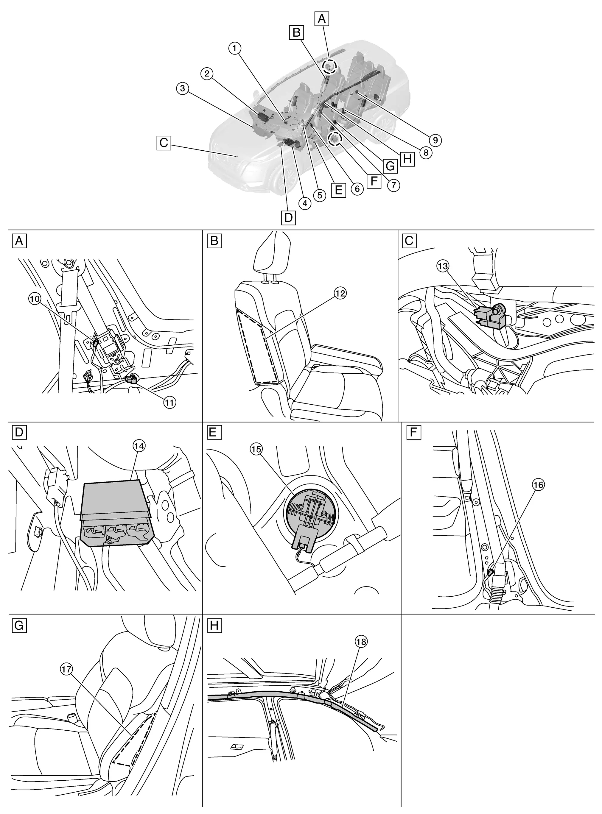
| A. | Right rear seat area (view with rear side finisher removed) | B. | Right rear seat area (view with rear side finisher removed) (view with luggage side lower finisher LH removed) | C. | Core support (view with air intake removed) |
| D. | Center console area (view with center console assembly removed) | E. | Driver door (view with front door finisher LH removed) | F. | B-pillar area (view with lower center pillar cover removed) |
| G. | Driver seat | H. | Roof area |
| No. | Component | Function |
|---|---|---|
| 1. | Occupant classification system control unit | Refer to System Description. |
| 2. | Front passenger air bag module | Refer to Front Passenger Air Bag Module. |
| 3. | Knee air bag module RH (if equipped) | Knee air bag module RH is built into instrument panel assembly. Knee air bag module RH mainly consists of air bag and inflator. Knee air bag RH inflates by breaking lid surface. |
| 4. | Knee air bag module LH | Knee air bag module LH is built into instrument panel assembly. Knee air bag module LH mainly consists of air bag and inflator. Knee air bag LH inflates by breaking lid surface. |
| 5. | Driver air bag module | Refer to Driver Air Bag Module. |
| 6. | Seat belt buckle switch LH (RH similar) | The seat belt buckle switches (Front Row LH/RH, 2ND Row LH/CTR/RH, 3RD Row LH/CTR/RH ) provide the seat belt buckle signals to the air bag diagnosis sensor unit and the combination meter. |
| 7. | Front center air bag module (If equipped) | Front center air bag module is built into seatback inside of driver seat. Front center air bag module mainly consists of air bag and inflator which inflates air bag. Front center air bag is installed to seatback inside stitch of driver seat indicating that front center air bag is equipped. Front center air bag inflates through seatback inside stitch of drivers seat. |
| 8. | 2nd row seat belt buckle switch LH (CTR and RH similar) | The seat belt buckle switches (Front Row LH/RH, 2ND Row LH/CTR/RH, 3RD Row LH/CTR/RH ) provide the seat belt buckle signals to the air bag diagnosis sensor unit and the combination meter. |
| 9. | 3rd row seat belt buckle switch CTR (LH and RH similar) | The seat belt buckle switches (Front Row LH/RH, 2ND Row LH/CTR/RH, 3RD Row LH/CTR/RH ) provide the seat belt buckle signals to the air bag diagnosis sensor unit and the combination meter. |
| 10. | Rear RH seat belt pre-tensioner (If equipped) (LH similar) | Refer to Rear Seat Belt Pre-tensioner. |
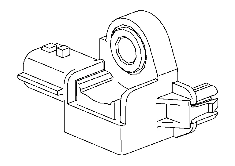
| 11. | Rear side air bag satellite sensor RH (RH similar) | Refer to Rear Side Air Bag Satellite Sensor. |
| 12. | Rear side air bag module RH (LH similar) | Refer to Rear Side Air Bag Module. |
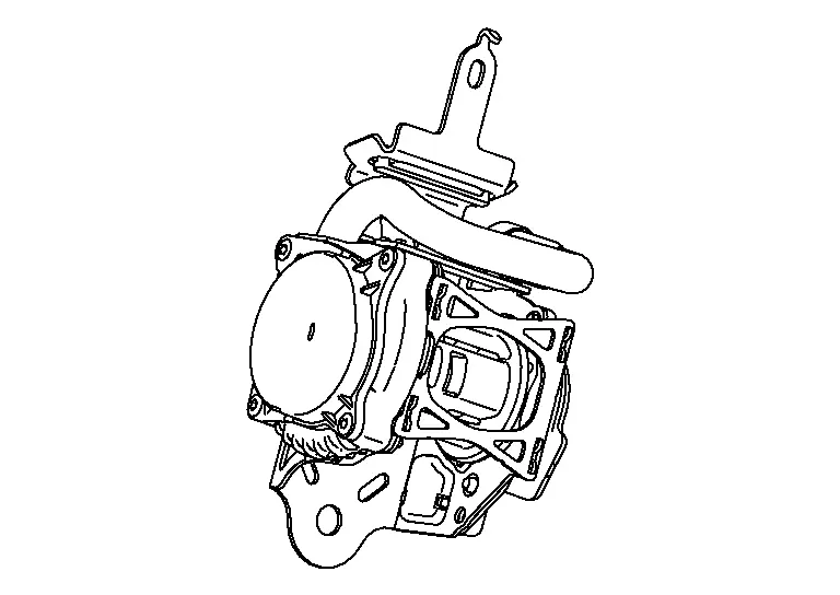
| 13. | Crash zone sensor | Refer to Crash Zone Sensor. |
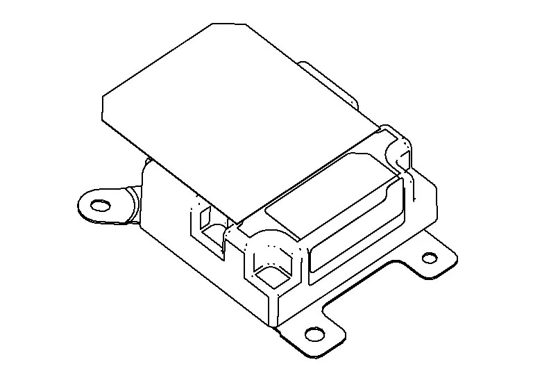
| 14. | Air bag diagnosis sensor unit | Refer to Air Bag Diagnosis Sensor Unit. |
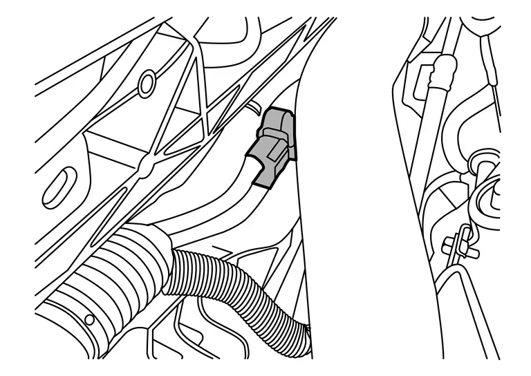
| 15. | Front door satellite sensor LH (if equipped) (RH similar) | Refer to Front Door Satellite Sensor. |
| 16 | Front LH seat belt pre-tensioner and lap pre-tensioner RH (LH similar) | Refer to Front Seat Belt Pre-tensioner. |
| 17. | Front side air bag module LH (RH similar) | Refer to Front Side Air Bag Module. |
| 18. | LH side curtain air bag module (view with headliner removed) (RH similar) | Refer to Side Curtain Air Bag Module. |
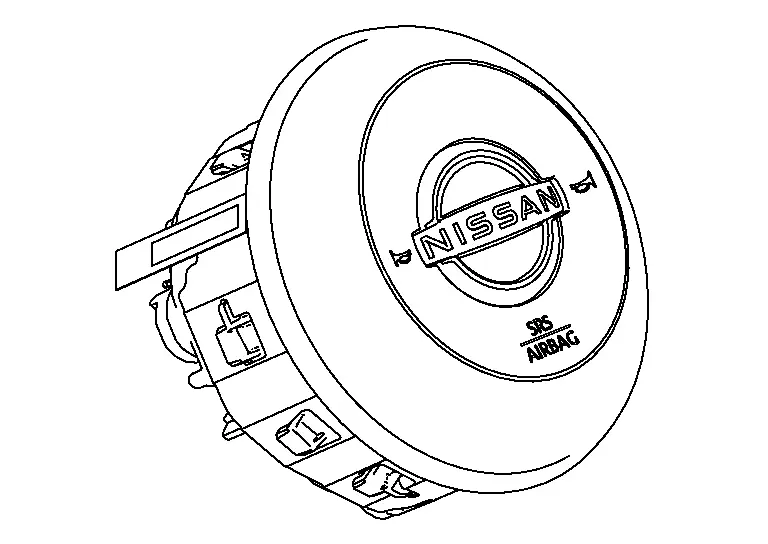
Driver Air Bag Module
The driver air bag module is dual stage and located in the steering wheel assembly. It operates with the SRS system in a frontal collision exceeding a specified level.
Front Passenger Air Bag Module
The front passenger air bag module is dual stage and is located behind the instrument panel assembly. It operates with the SRS system in a frontal collision exceeding a specified level. Refer to System Description for more information.
Front Center Air Bag Module
Front center air bag module is built into seat back inside of driver seat. Front center air bag module mainly consists of air bag and inflator which inflates air bag. Front center air bag is installed to seat back inside stitch of driver seat indicating that front center air bag is equipped. Front center air bag inflates through seat back inside stitch of drivers seat.
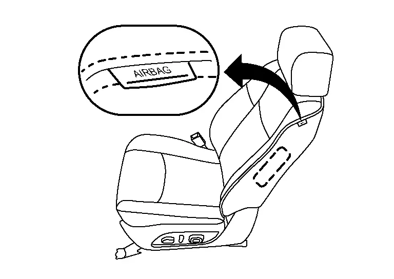
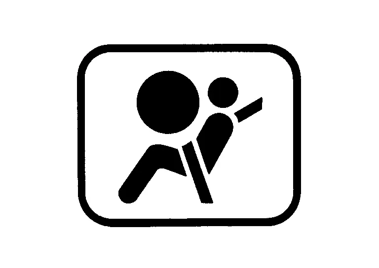
Front Side Air Bag Module
Front side air bag modules are built into the front seatback assemblies. Vehicles with side air bags are equipped with labels as shown.
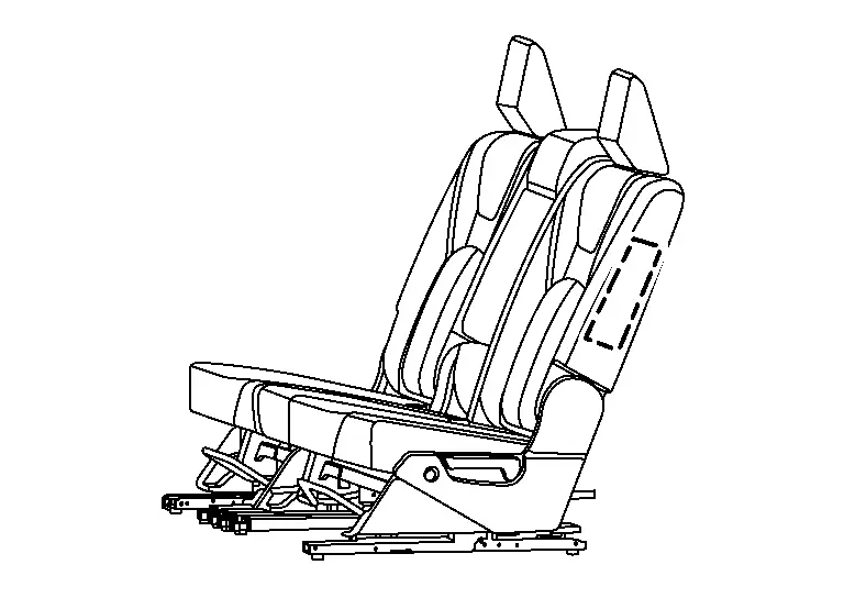
Rear Side Air Bag Module
Rear side air bag modules are built into the 2nd row seat back assemblies. Vehicles with side air bags are equipped with labels on the seat cushion outer finishers.
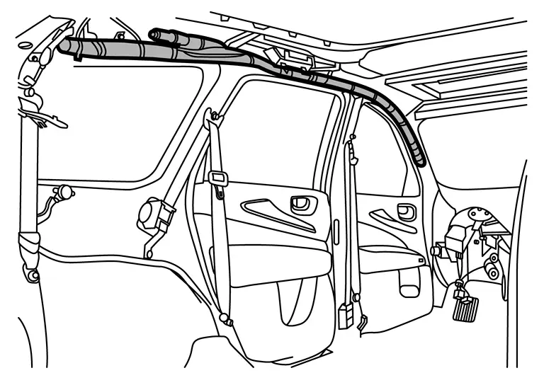
Side Curtain Air Bag Module
Side curtain air bag modules are located above the vehicle headlining. Vehicles with side curtain air bags are equipped with labels on the pillar upper finishers.
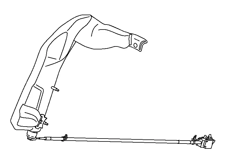
Front Seat Belt Pre-tensioner
The seat belt pre-tensioner system with load limiter is installed for both the driver's seat and the front passenger's seat. It operates simultaneously with the SRS air bag system in the event of a frontal collision with an impact exceeding a specified level.
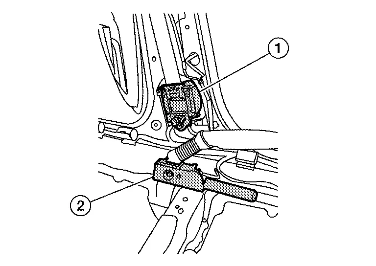
When the frontal collision with an impact exceeding a specified level occurs, seat belt slack resulting from clothing or other factors is immediately taken up by the pre-tensioner (1) as well as the lap pretensioner (2). Nissan Pathfinder Vehicle passengers are securely restrained.
When passengers in a vehicle are thrown forward in a collision and the restraining force of the seat belt exceeds a specified level, the load limiter permits the specified extension of the seat belt by the twisting of the ELR shaft, and a relaxation of the chest-area seat belt web tension while maintaining force.
Rear Seat Belt Pre-tensioner
The seat belt pre-tensioner system with load limiter is installed for both the rear RH and LH. It operates simultaneously with the SRS air bag system in the event of a frontal collision with an impact exceeding a specified level.
When the frontal collision with an impact exceeding a specified level occurs, seat belt slack resulting from clothing or other factors is immediately taken up by the pre-tensioner Nissan Pathfinder Vehicle passengers are securely restrained.
When passengers in a vehicle are thrown forward in a collision and the restraining force of the seat belt exceeds a specified level, the load limiter permits the specified extension of the seat belt by the twisting of the ELR shaft, and a relaxation of the chest-area seat belt web tension while maintaining force.
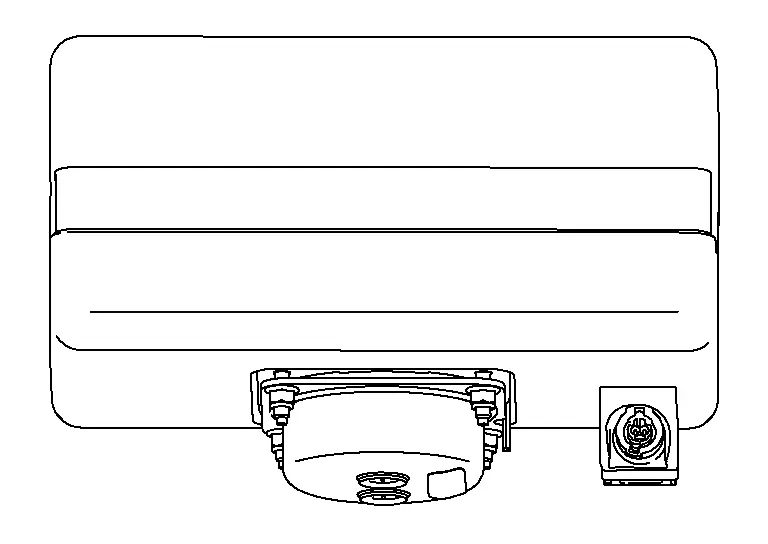
Air Bag Diagnosis Sensor Unit
The air bag diagnosis sensor unit is located under the center console assembly. The air bag diagnosis sensor unit receives signals from multiple SRS sensors and controls the deployment of the air bags. The deployment of the air bags depends on the type and severity of the collision. The air bag diagnosis sensor unit has self-diagnosis capability through the use of the CONSULT as well as flash codes displayed by the air bag warning lamp.
Crash Zone Sensor
The crash zone sensor is located behind the radiator and underneath the front air duct. The crash zone sensor sends signals to the air bag diagnosis sensor unit during a frontal collision. This sensor may be identified by a yellow connector.
Rear Side Air Bag Satellite Sensor
The rear side air bag satellite sensors are located behind the luggage side lower finisher LH and RH. The rear side air bag satellite sensors send signals to the air bag diagnosis sensor unit during a side collision. These sensors may be identified by yellow connectors.
Front Door Satellite Sensor
The front door satellite sensors are located in the driver and passenger doors. The front door satellite sensors send signals to the air bag diagnosis sensor unit during a side collision. These sensors may be identified by yellow connectors.
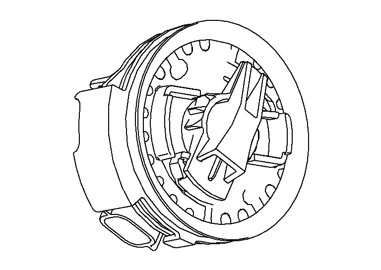
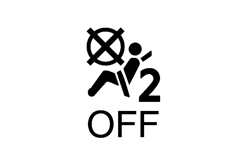
Front Passenger Air Bag Off Indicator
Front passenger air bag OFF indicator indicates whether or not passenger air bag is in the activation mode based on the judgment of the occupant detection system.
Diagnosis System (air Bag) Nissan Pathfinder
Diagnosis Description
CAUTION:
-
Do not use electrical test equipment on any circuit related to the SRS unless instructed to do so in this Service Manual. SRS wiring harnesses can be identified by yellow and/or orange harness connectors.
-
Do not attempt to repair, splice or modify SRS wiring harnesses. If a harness is damaged, replace it with a new one.
-
Keep ground connections clean.
HOW TO PERFORM TROUBLE DIAGNOSES FOR QUICK AND ACCURATE REPAIR
-
Obtain information about the symptom.
-
WHAT - vehicle model
-
WHEN - date, frequencies
-
WHERE - road conditions
-
HOW - operating conditions, symptoms, passengers
-
-
Perform Preliminary Check.
-
Battery
-
Fuses
-
Harness connections
-
DIAGNOSIS METHODS
SRS self-diagnosis results can be read by using the AIR BAG warning lamp or CONSULT.
The User Mode is for the customer (driver). This mode warns the driver of a system malfunction through the AIR BAG warning lamp.
The Diagnosis Mode is for the technician. This mode helps the technician locate the malfunctioning circuit or part.
| User Mode | Diagnosis Mode | Display type | |
| AIR BAG warning lamp | X | X | ON/OFF |
| CONSULT | — | X | Monitoring |
SRS Operation Check
USER MODE
-
Press the push-button ignition switch from OFF to ON and check that the air bag warning lamp blinks.
-
Compare the blinking pattern with the examples in the table.
| Warning lamp | SRS condition | Reference item |
|---|---|---|
|
|
|
— |
|
|
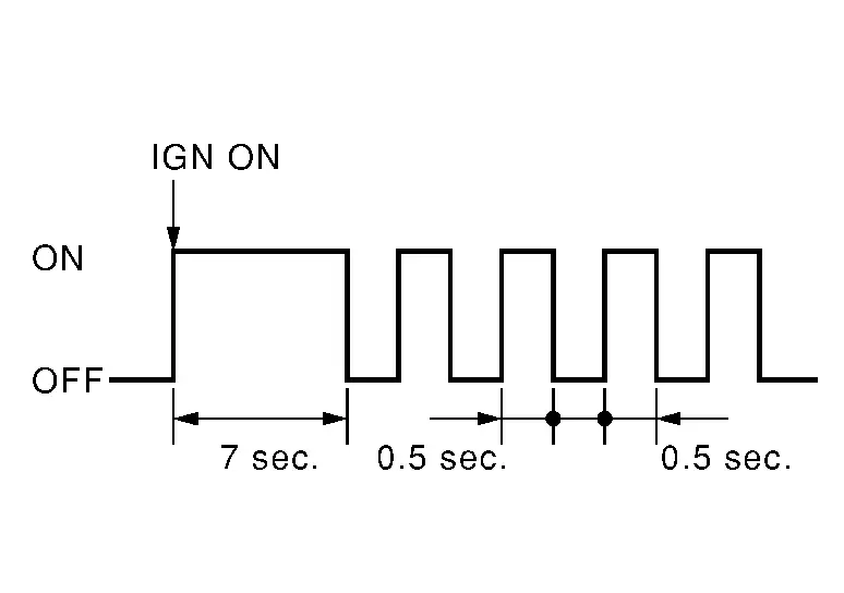
The system is malfunctioning and needs to be repaired. | Refer to Trouble Diagnosis with CONSULT or Trouble Diagnosis without CONSULT. |
| Zero point reset is incomplete | Refer to Special Repair Requirement. | |
|
|
|
Refer to For Frontal Collision or For Side and Rollover Collision. |
|
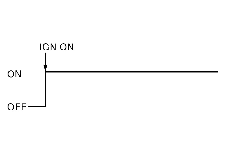
Refer to AIR BAG Warning Lamp Does Not Turn Off. | |
|
|
|
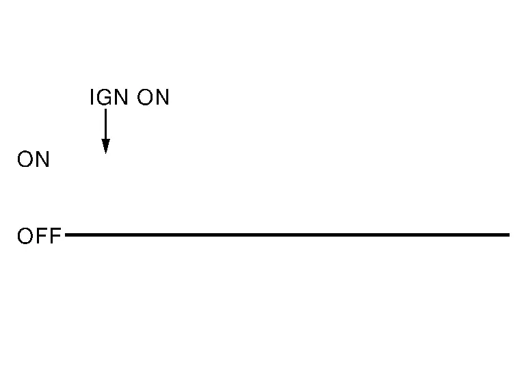
Refer to AIR BAG Warning Lamp Does Not Turn On. |
Trouble Diagnosis with CONSULT
-
Connect CONSULT.
-
DTC is displayed on SELF-DIAG RESULTS.
 NOTE:
NOTE:
If a malfunction is not detected on SELF-DIAG RESULTS [CURRENT], but a malfunction is detected during SRS Operation Check, the following cases may exist:
-
SELF-DIAG [PAST] memory might not be erased. Refer to SRS Final Check.
-
SRS system malfunctions intermittently. Refer to Inspection Procedure.
Trouble Diagnosis without CONSULT
DIAGNOSIS MODE
 NOTE:
NOTE:
Diagnosis Mode can not be entered if a malfunction is not detected in User Mode.
-
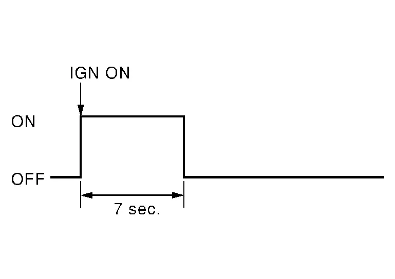
Ignition switch ON.
-
After AIR BAG warning lamp lights for 7 seconds, ignition switch OFF within 1 second.
-
Wait more than 3 seconds.
-
Repeat steps 1 to 3 two more times (3 times total).
-
Ignition switch ON.
SRS is now in Diagnosis Mode. Refer to Flash Code Index.
SRS History Check
SRS HISTORY CHECK
-
Check repair history of the SRS. If no repairs have been made, perform SRS Operation Check. If repairs have been made, GO TO step 2.
-
Erase "SELF-DIAG [PAST]" after repair. Refer to SRS Final Check.
SRS Final Check
DIAGNOSIS MODE
-
Connect CONSULT.
-
Confirm that zero point reset of OCS is complete.
-
If no DTCs are detected on “SELF-DIAG RESULTS [CURRENT]”, repair of SRS is completed. Go to step 4.
If any DTCs are detected on “SELF-DIAG RESULTS [CURRENT]”, the malfunction has not been repaired completely or another malfunction is being detected. Perform SRS Operation Check again. Refer to SRS Operation Check.
-
Touch “ERASE”.
 NOTE:
NOTE:
Touching “ERASE” will clear the SRS memory of the malfunction (“SELF-DIAG [PAST]”). If “SELF-DIAG [PAST]” is not erased, User Mode may show the previous system malfunction even if the malfunction has been repaired completely.
-
Check that no malfunction is detected in “SELF-DIAG [PAST]”.
-
Exit Diagnosis Mode and disconnect the CONSULT.
-
Perform SRS Operation Check. Refer to SRS Operation Check.
CONSULT Function (AIR BAG)
CAUTION:
After disconnecting the CONSULT vehicle interface (VI) from the data link connector, the ignition must be cycled OFF → ON (for at least 5 seconds) → OFF. If this step is not performed, the BCM may not go to ”sleep mode”, potentially causing a discharged battery and a no-start condition.
CONSULT can display each diagnostic item using the diagnostic test modes shown following.
| Diagnostic Test Mode | Diagnostic Item | Description |
|---|---|---|
| Self Diagnostic Result | SELF-DIAG RESULT [CURRENT] | A current Self-diagnosis result (also indicated by the number of warning lamp flashes in the Diagnosis mode) is displayed on the CONSULT screen in real time. This refers to a malfunctioning part requiring repairs. |
| Data Monitor | DATA MONITOR | Displays air bag diagnosis sensor unit input/output data in real time. |
| ECU Identification | ECU DISCRIMINATED NO. | Air bag diagnosis sensor unit ECU discriminated number (identification number) or part number is displayed. Air bag diagnosis sensor unit has individual ECU discriminated number (identification number) or part number based on model and equipment. |
| Trouble Diagnostic Record | TROUBLE DIAG RECORD [PAST] | With TROUBLE DIAG RECORD, diagnosis results previously erased by a reset operation can be displayed on the CONSULT screen. |
CONSULT Function (OCCUPANT DETECTION)
WORK SUPPORT
CONSULT can display each diagnostic item using the diagnostic test modes shown following.
| Diagnostic Item | Description |
|---|---|
| Zero point reset function | Perform zero point reset. Refer to Special Repair Requirement. |
DATA MONITOR
 NOTE:
NOTE:
The following table includes information (items) inapplicable to this Nissan Pathfinder vehicle. For information (items) applicable to this vehicle, refer to CONSULT display items.
| Monitor Item | Contents |
|---|---|
|
Buckle Switch Status [Not Moni/Unfasten/Fasten/Reload] |
The switch status input from seat belt buckle switch (passenger side).
|
|
Buckle Switch Spec [Not Moni/Nor Op/Nor Cl/Frm ACU] |
Displays the spec of the seat belt buckle switch (passenger side).
|
|
Buckle Switch Status (Comm) [Not Moni/Moni(wir)/Frm ACU] |
Displays the status of the seat belt buckle switch (passenger side) signal.
|

Nissan Pathfinder (R53) 2022-2026 Service Manual
System Description
Contact Us
Nissan Pathfinder Info Center
Email: info@nipathfinder.com
Phone: +1 (800) 123-4567
Address: 123 Pathfinder Blvd, Nashville, TN 37214, USA
Working Hours: Mon–Fri, 9:00 AM – 5:00 PM (EST)
