Nissan Pathfinder: Starting System - System Description
- Component Parts. Starting System
- Starting System (with Stop/start System)
- Starting System (without Stop/start System)
Component Parts. Starting System Nissan Pathfinder 2026
Component Parts Location
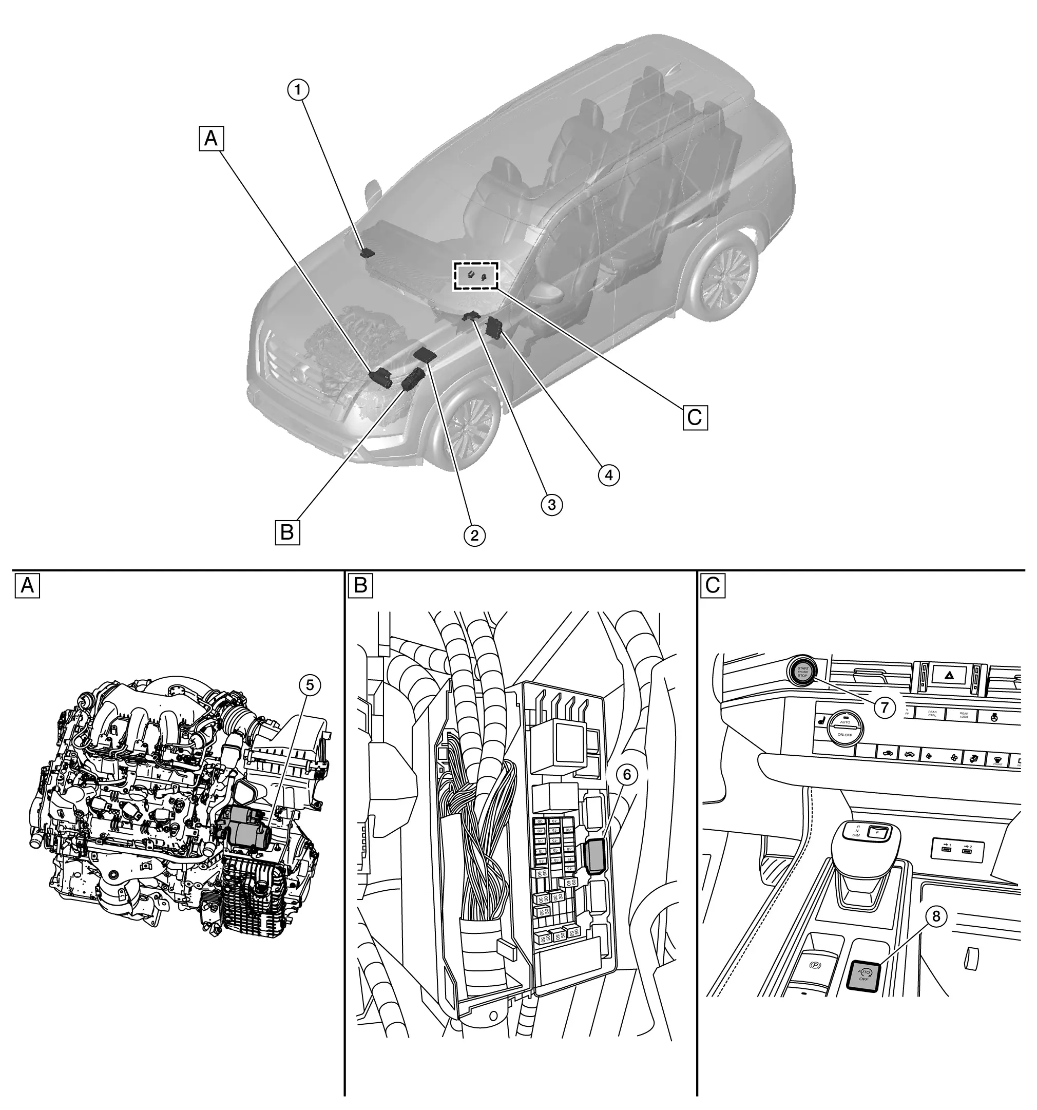
| A. | View with engine and transmission removed | B. | Engine room left side | C. | Center console |
| No. | Component | Function |
|---|---|---|
| 1. | Intelligent Key unit |
Intelligent Key unit transmits key signal to the BCM. Refer to Component Parts Location for detailed component location. |
| 2. |
IPDM E/R (Intelligent Power Distribution Module Engine Room) |
CPU inside IPDM E/R controls starter relay. Starter relay is built into the IPDM E/R. Refer to System Description. |
| 3. | Electric shift control module |
Electric shift control module supplies power to the starter relay inside IPDM E/R when the lever is shifted to the "P" or "N" position. Refer to Component Parts Location for detailed component location. |
| 4. |
BCM (Body Control Module) |
BCM controls starter cut relay. Refer to System Description. |
| 5. | Starter motor | Refer to Starter Motor. |
| 6. | Starter cut relay and direct fuel injector relays 1 and 2 (starter cut relay) | Power is supplied to the starter cut relay with BCM control. |
| 7. | Push-button ignition switch | Supplies ignition switch status to the IPDM E/R. |
| 8. |
Stop/start off switch (If equipped) |
Sends signal to BCM to shut off the idle stop system. Refer to Stop/Start Off Switch. |
Starter Motor
-
Located toward the rear of the engine, just before the transmission.
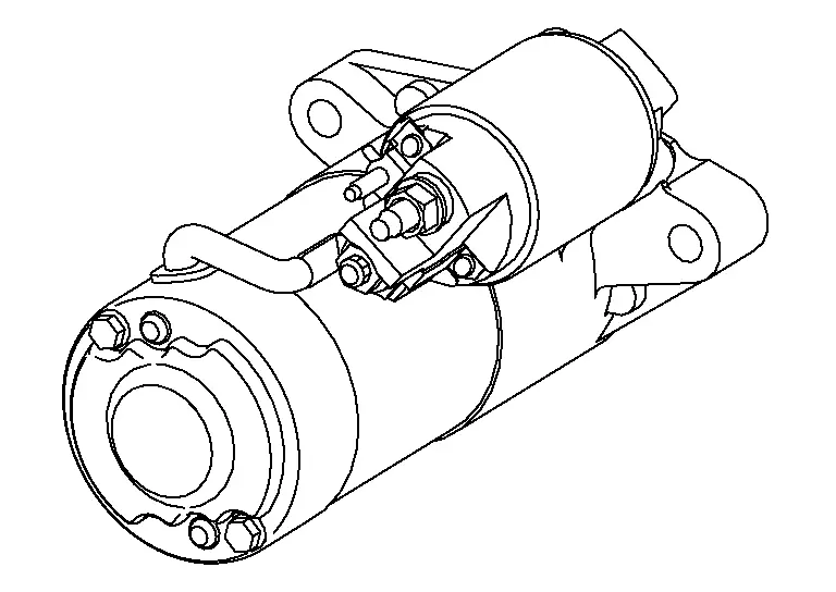
-
The starter motor plunger closes and the motor is supplied with battery power, which in turn cranks the engine, when the “S” terminal is supplied with electric power.
-
“B” terminal: The “B” terminal is constantly supplied with battery power.
-
“S” terminal: The starter motor magnetic switch (“S” terminal) is supplied with power when the cranking condition is satisfied.
Stop/Start Off Switch
-
Located on the center console, just behind the shift selector.
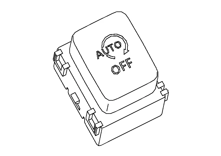
-
The stop/start off switch shuts off the idle stop system by sending a signal to the BCM.
Starting System (with Stop/start System) Nissan Pathfinder 2026
System Description
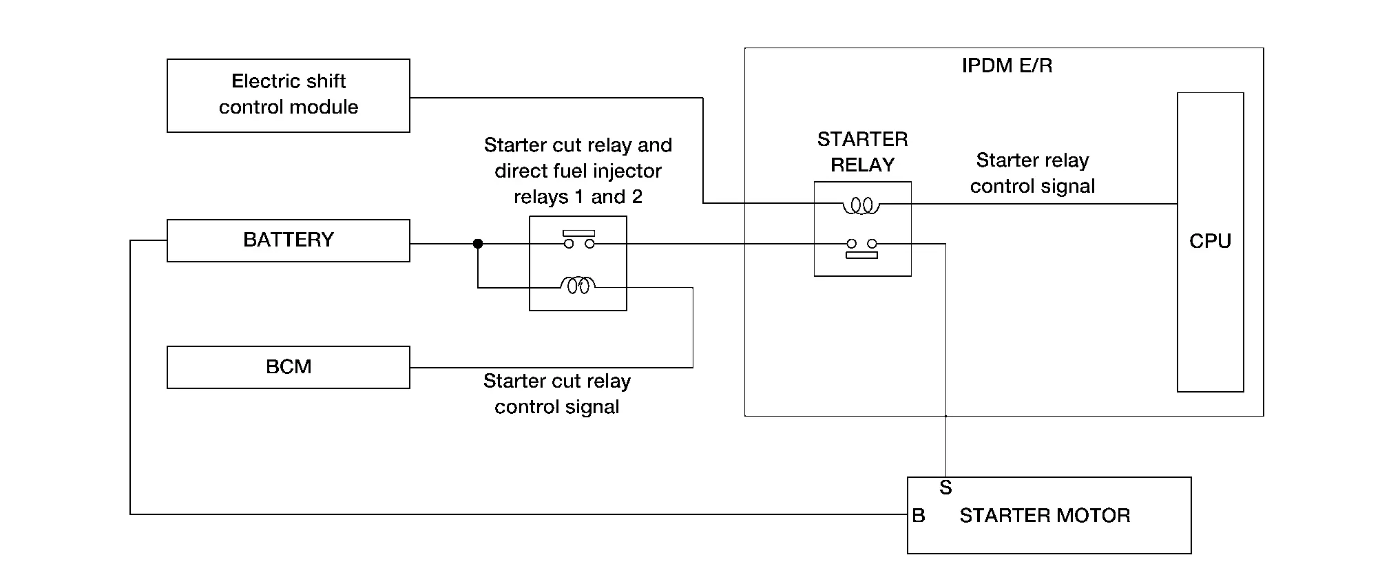
SYSTEM DIAGRAM
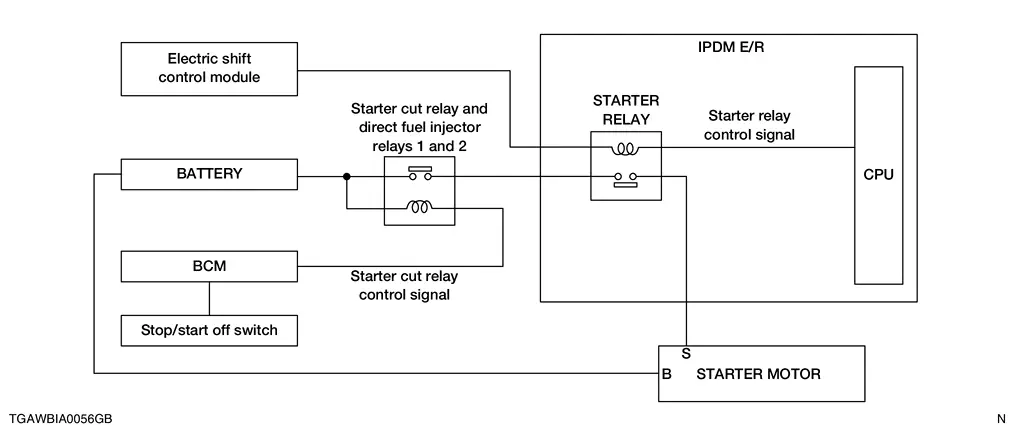
INPUT SIGNAL AND OUTPUT SIGNAL CHART
| Component | Signal |
|---|---|
| IPDM E/R | Transmits starter relay control signal to electric shift control module. |
| BCM | Transmits starter cut relay control signal to starter motor. |
| Stop/start off switch | Transmits stop/start off switch signal to the BCM. |
SYSTEM DESCRIPTION
-
“B” terminal is constantly supplied with battery power.
-
When selector lever is P or N, power is supplied to starter relay by electric shift control module.
-
When starter operating condition is satisfied, IPDM E/R turns starter relay ON by starter relay control signal.
-
When engine cranking condition is satisfied, BCM turns starter cut relay ON by starter cut relay control signal.
-
Then battery power is supplied to starter motor (“S” terminal) through starter cut relay and starter relay.
-
Stop/start off switch shuts off idle stop system by sending signal to BCM.
-
When selector lever is D, and other engine criteria are met, the engine shuts down at idle, restarting when brake pedal is released.
Starting System (without Stop/start System) Nissan Pathfinder Fifth generation
System Description
SYSTEM DIAGRAM
INPUT SIGNAL AND OUTPUT SIGNAL CHART
| Component | Signal |
|---|---|
| IPDM E/R | Transmits starter relay control signal to electric shift control module. |
| BCM | Transmits starter cut relay control signal to starter motor. |
SYSTEM DESCRIPTION
-
“B” terminal is constantly supplied with battery power.
-
When selector lever is P or N, power is supplied to starter relay by electric shift control module.
-
When starter operating condition is satisfied, IPDM E/R turns starter relay ON by starter relay control signal.
-
When engine cranking condition is satisfied, BCM turns starter cut relay ON by starter cut relay control signal.
-
Then battery power is supplied to starter motor (“S” terminal) through starter cut relay and starter relay.

Nissan Pathfinder (R53) 2022-2026 Service Manual
System Description
- Component Parts. Starting System
- Starting System (with Stop/start System)
- Starting System (without Stop/start System)
Contact Us
Nissan Pathfinder Info Center
Email: info@nipathfinder.com
Phone: +1 (800) 123-4567
Address: 123 Pathfinder Blvd, Nashville, TN 37214, USA
Working Hours: Mon–Fri, 9:00 AM – 5:00 PM (EST)
