Nissan Pathfinder: System Description - Structure and Operation ++
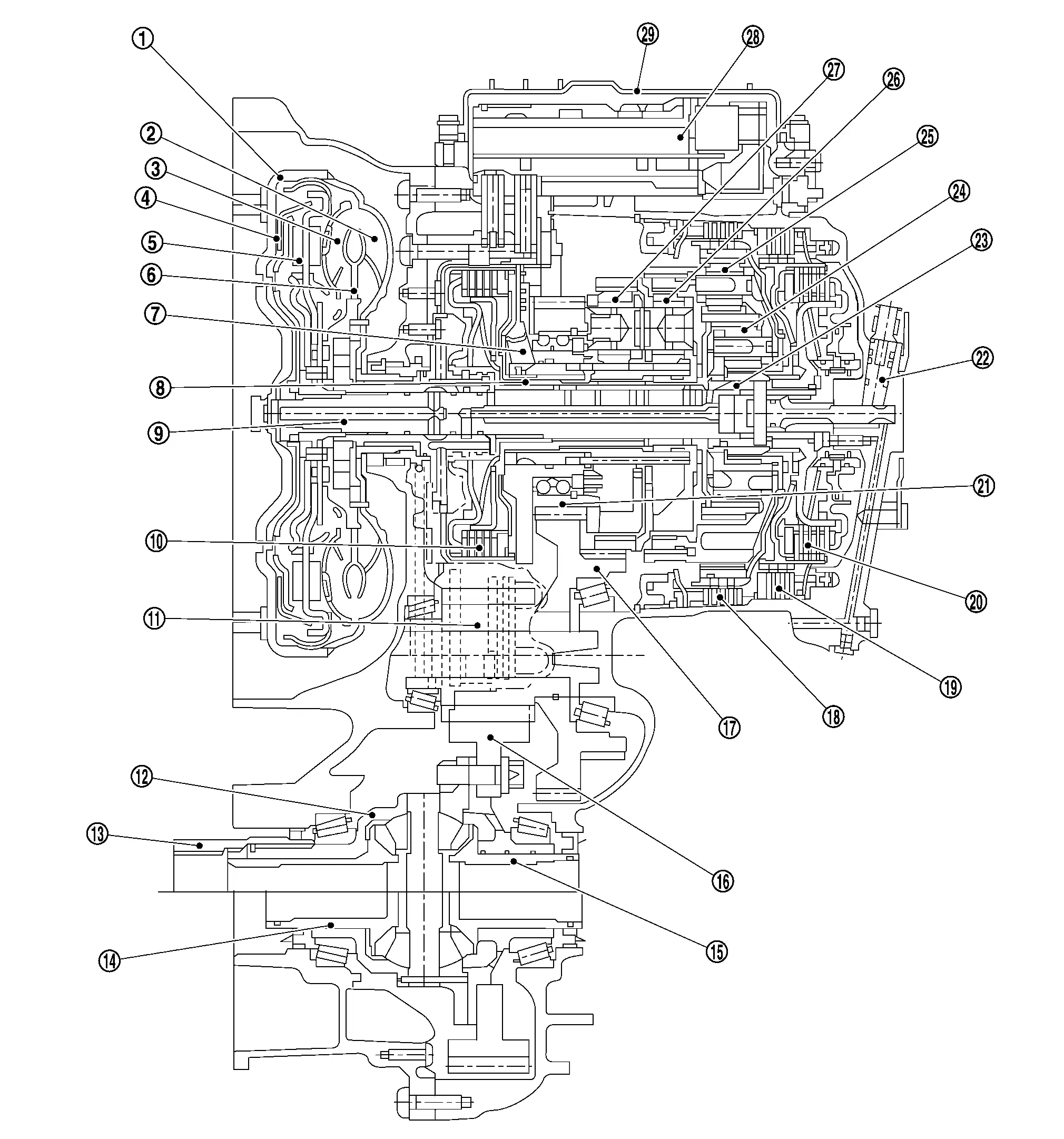
Transaxle Cross-Sectional View
 |
Torque converter |  |
Impeller |  |
Turbine wheel |
 |
Torque converter lock-up clutch |  |
Torsional damper |  |
Stator |
 |
Dog clutch F position sensor |  |
Dog clutch F |  |
Input shaft |
 |
Clutch E |  |
Oil pump |  |
Front axle differential |
 |
Rear axle output (AWD models) |  |
Right front axle output |  |
Left front axle output |
 |
Final gear |  |
Parking interlock gear |  |
Brake D |
 |
Brake C |  |
Clutch B |  |
Spur pinion |
 |
Dog clutch A position sensor |  |
Dog clutch A |  |
Planetary gear set 1 |
 |
Planetary gear set 2 |  |
Planetary gear set 3 |  |
Planetary gear set 4 |
 |
Control valve assembly |  |
Oil pan |
System Description
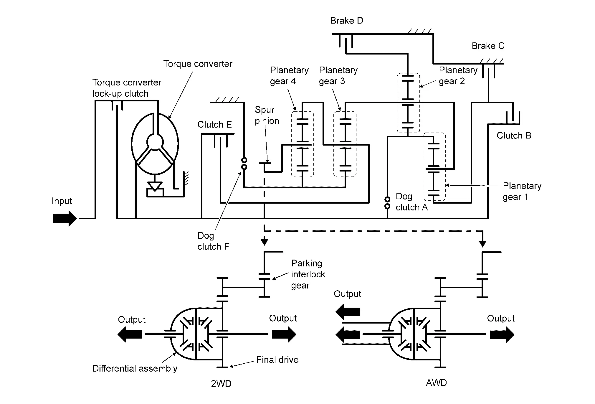
DESCRIPTION
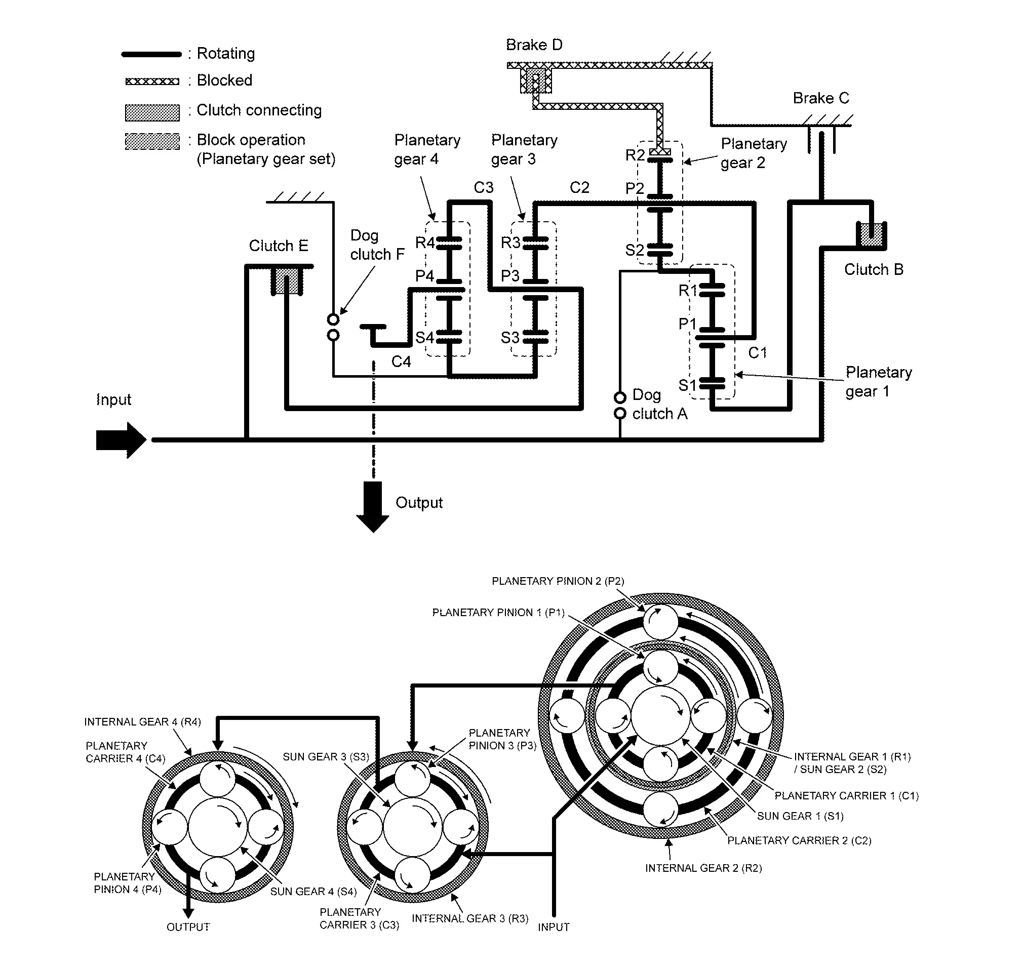
The automatic transmission‘s mode of operation is based on the individual gears being shifted by a combination of the respective gearsets. To this end, various shift elements are used. This transmission uses 2 multidisk brakes, 2 multidisk clutches and 2 dog clutches.
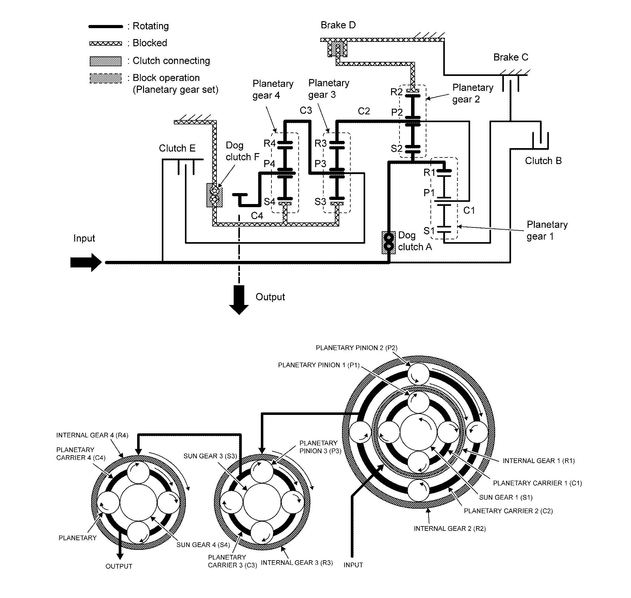
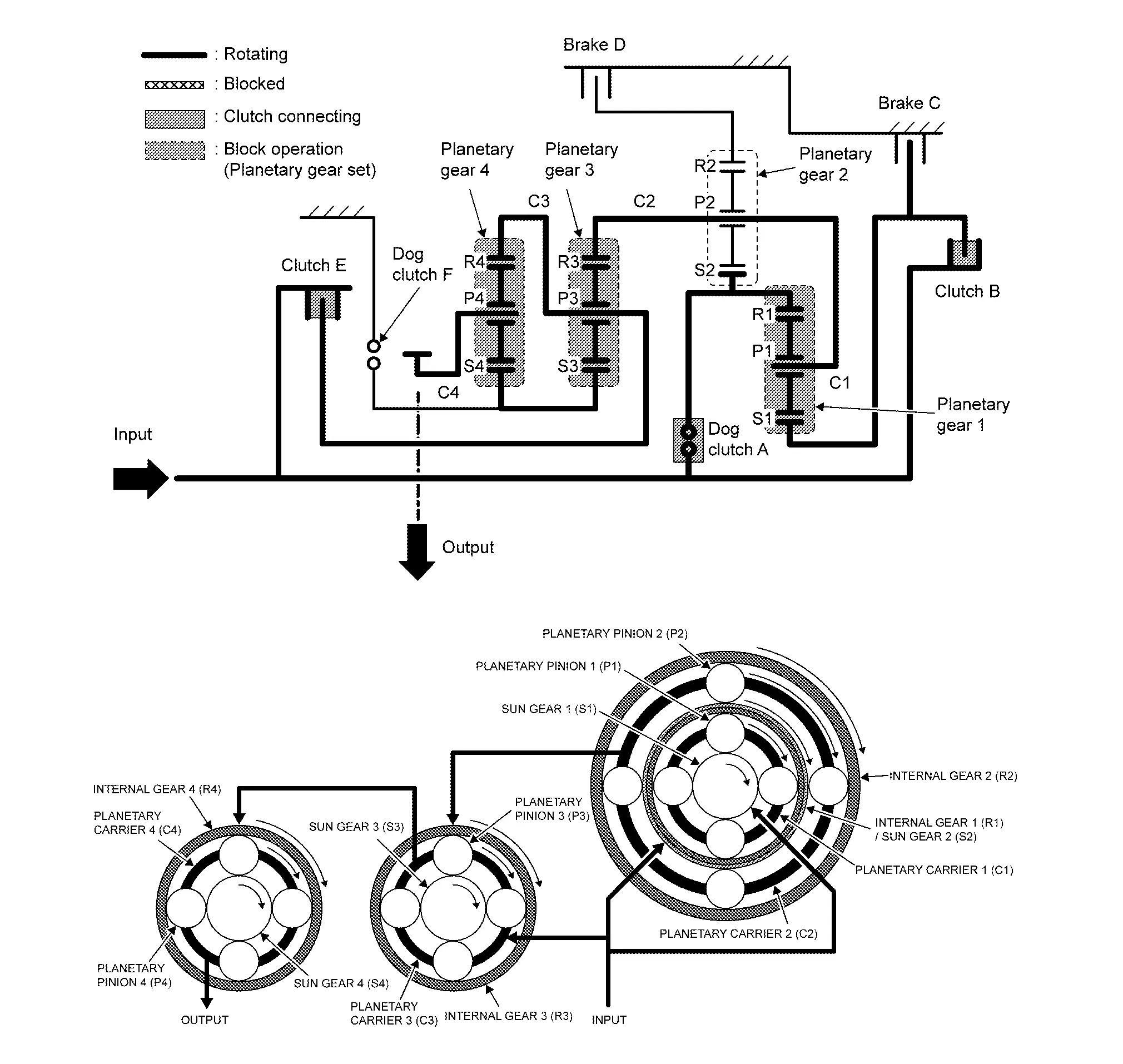
SYSTEM DIAGRAM
CLUTCH AND BRAKE CHART
 : Engagement
| Gear position | Clutch/Brake Operation | |||||
|---|---|---|---|---|---|---|
| Dog clutch | Clutch | Brake | ||||
| A | F | B | E | C | D | |
| P |  |
 |
||||
| N |  |
 |
||||
| R |  |
 |
 |
|||
| 1 |  |
 |
 |
|||
| 2 |  |
 |
 |
|||
| 3 |  |
 |
 |
|||
| 4 |  |
 |
 |
|||
| 5 |  |
 |
 |
|||
| 6 |  |
 |
 |
|||
| 7 |  |
 |
 |
|||
| 8 |  |
 |
 |
|||
| 9 |  |
 |
 |
|||
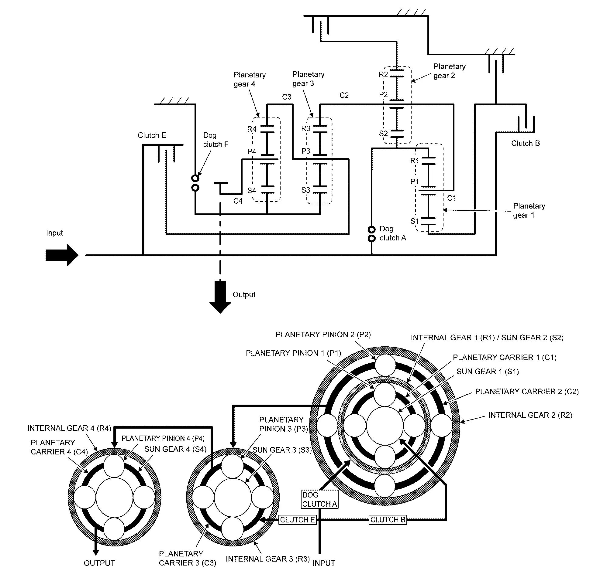
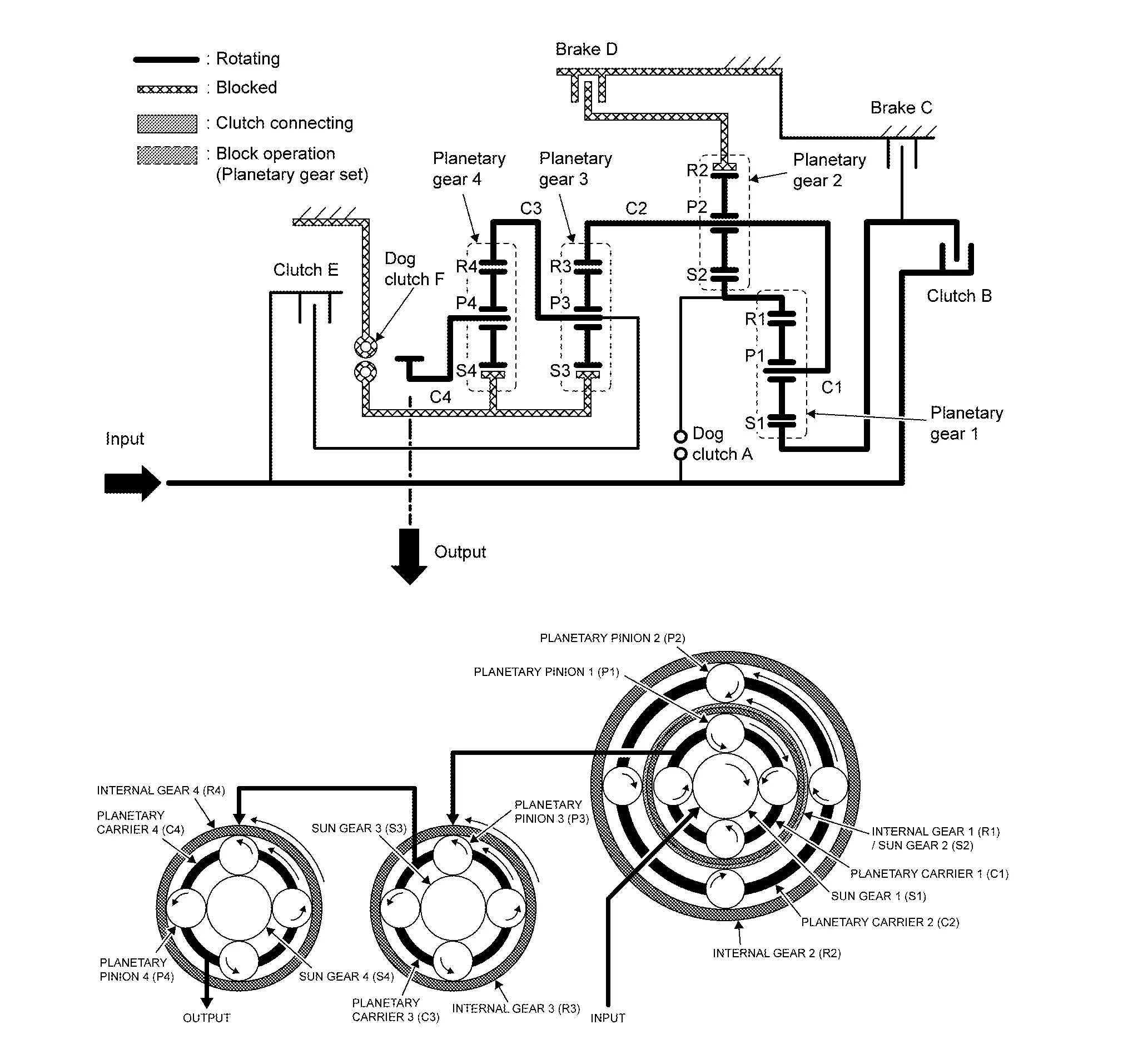
PLANETARY GEAR SET
Planetary gear set 1 and 2 are arranged they are overlapping. The internal gear of planetary gear set 1 and the sun gear of planetary gear set 2 are in a integral structure, and planetary carrier 1 and 2 that have four planetary pinions in their own respectively are common part.
Planetary gear set 3 and 4 are arranged in parallel. The planetary carrier of the planetary gear set 3 and the internal gear of the planetary gear set 4 are in a integral structure and the sun gear of planetary gear set 3 and 4 are common part.
TRACTION TRANSMISSION OF EACH RANGE
Neutral gear (P position and N position)
The drive force from the input shaft is not transmitted because dog clutch A, clutch B and clutch E are released.
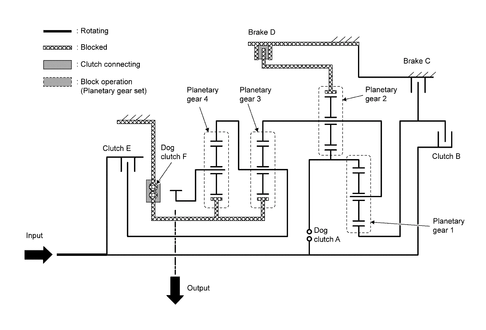
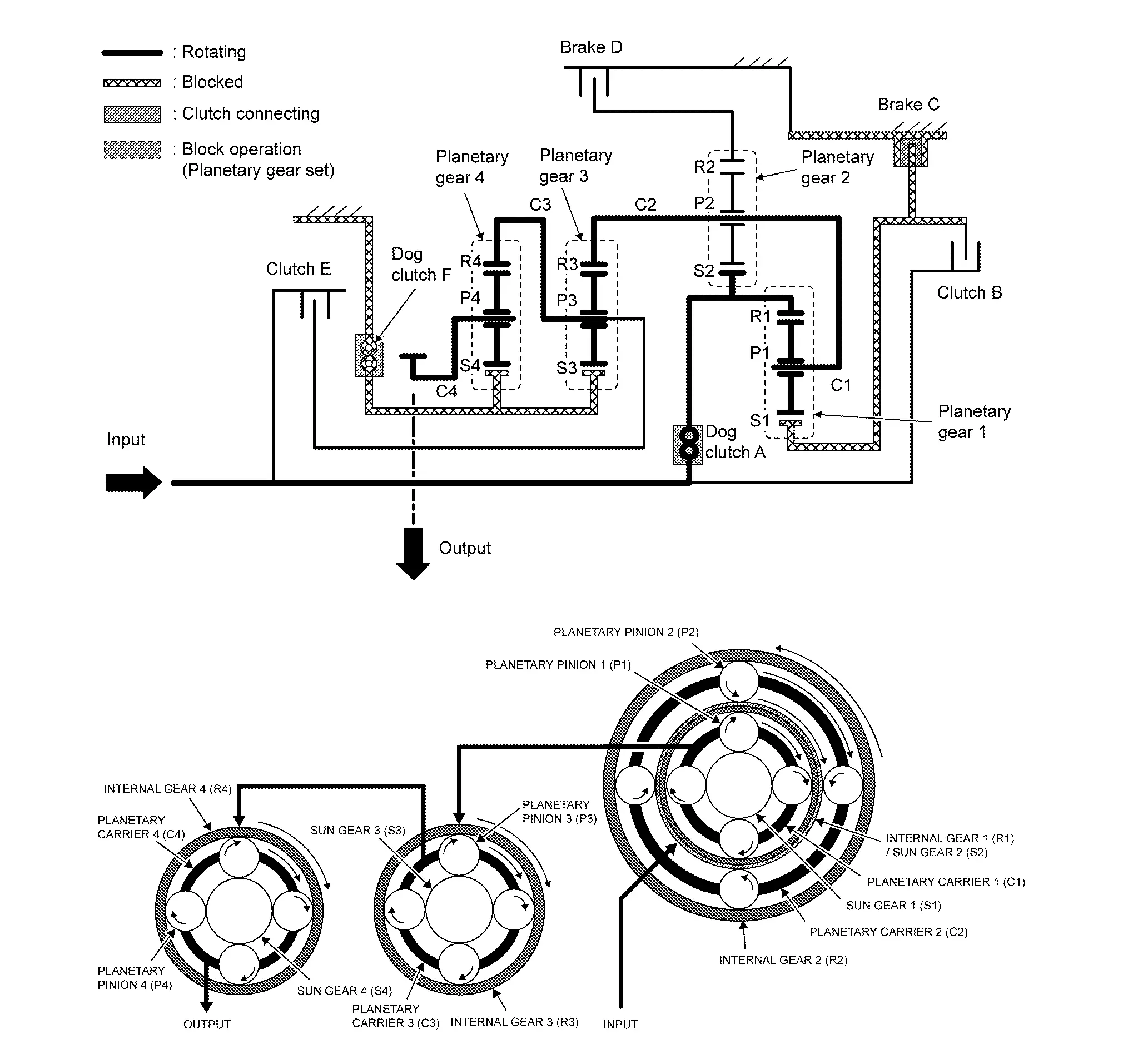
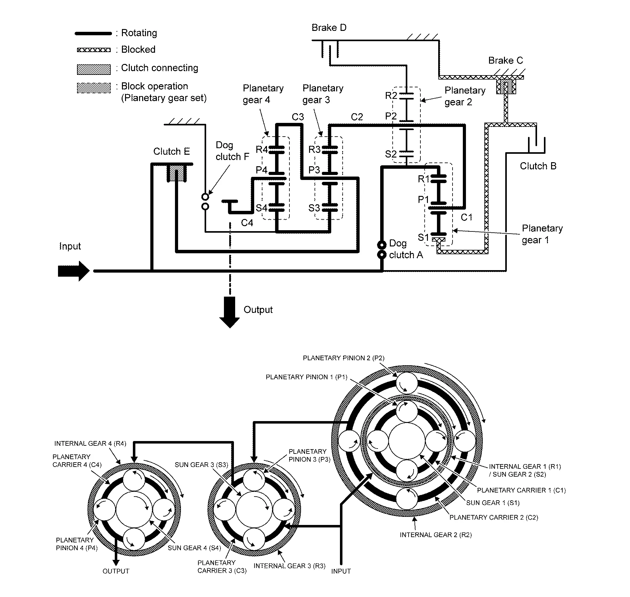
1st gear
-
Input shaft and sun gear 2 are directly connected by the dog clutch A.
-
Internal gear 2 is fixed by the brake D.
-
Sun gear 3 and 4 are fixed by the dog clutch F.
-
Transmission input revolution is decreased by the internal gear of the transmission.
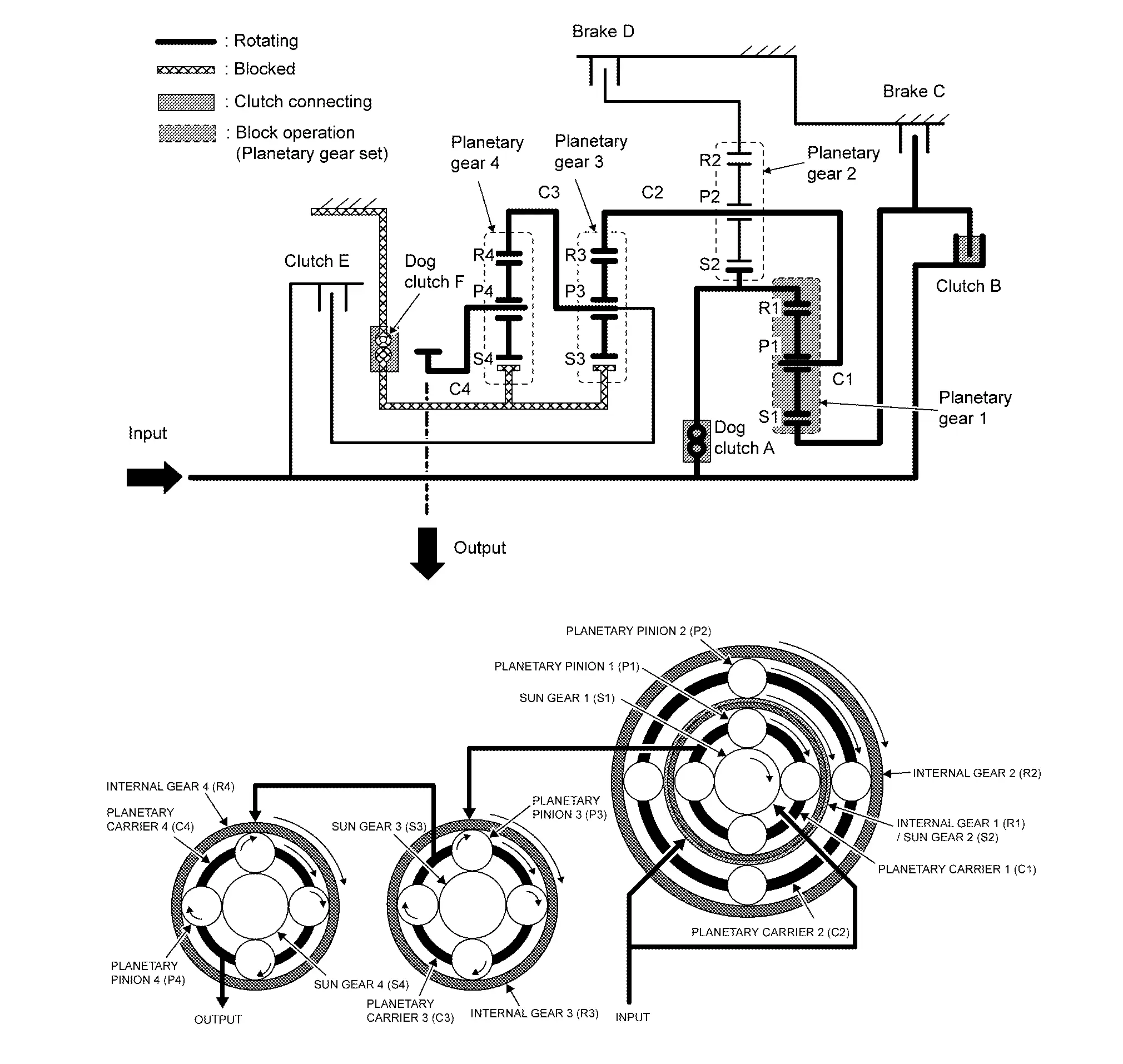
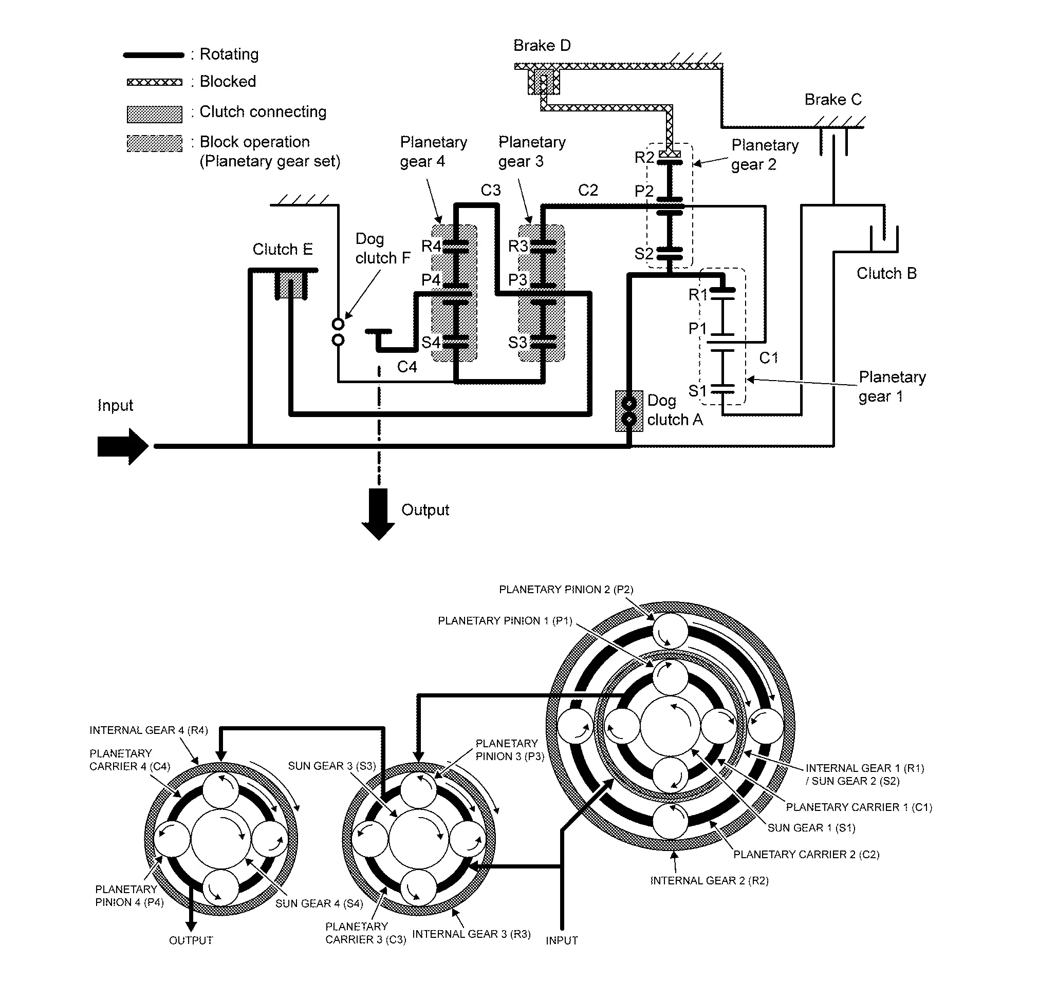
2nd gear
-
Input shaft and internal gear 1 are directly connected by the dog clutch A.
-
Sun gear 1 is fixed by the brake C.
-
Sun gear 3 and 4 are fixed by the dog clutch F.
-
Transmission input revolution is decreased by the internal gear of the transmission.
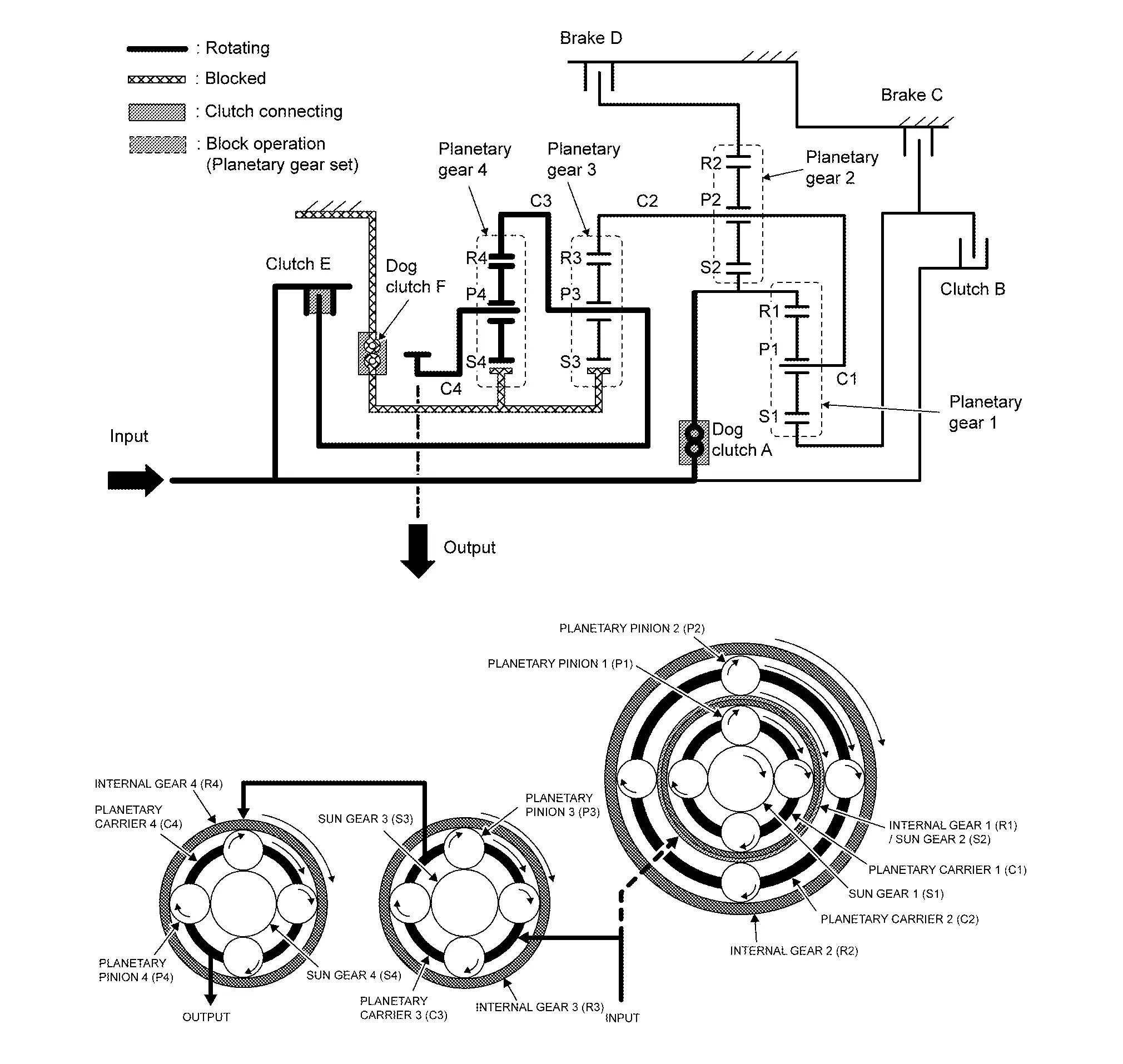
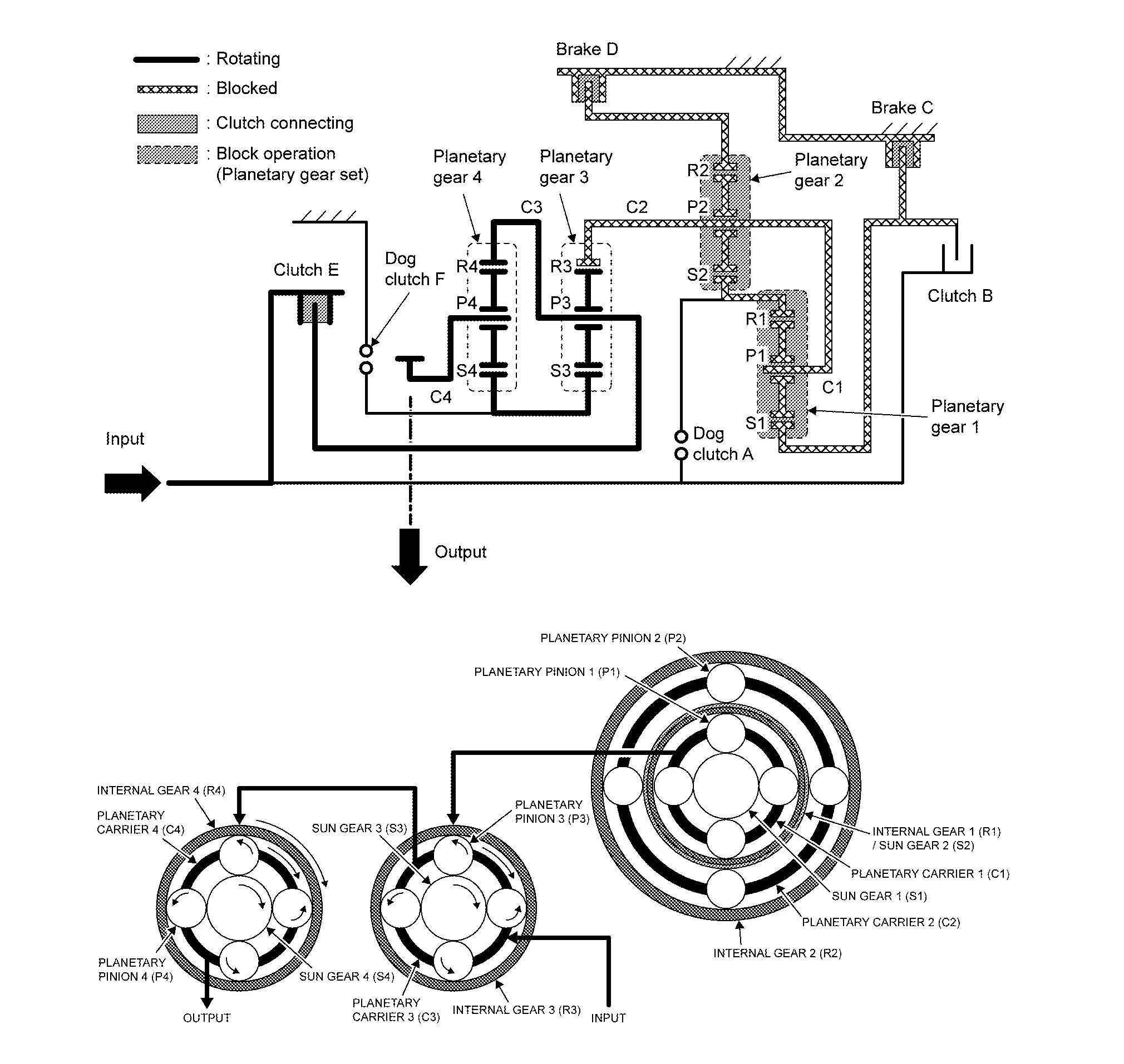
3rd gear
-
Input shaft, sun gear 2, and internal gear 1 are directly connected by the dog clutch A.
-
Input shaft and sun gear 1 are directly connected by the clutch B.
-
Sun gear 3 and 4 are fixed by the dog clutch F.
-
Transmission input revolution is decreased by the internal gear of the transmission.
4th gear
-
Input shaft and internal gear 1/sun gear 2 are directly connected by the dog clutch A. However, planetary gear 1 and 2 are not affect in power transmission.
-
Input shaft and planetary carrier 3/internal gear 4 are directly connected by the clutch E.
-
Sun gear 3 and 4 are fixed by the dog clutch F.
-
Transmission input revolution is decreased by the internal gear of the transmission.
5th gear
-
Input shaft and internal gear 1/sun gear 2 are directly connected by the dog clutch A.
-
Input shaft and sun gear 1 are directly connected by the clutch B.
-
Input shaft and planetary carrier 3/internal gear 4 are directly connected by the clutch E.
-
Transmission output revolution keeps the initial input revolution because it does not affect the internal gear of the transmission.
6th gear
-
Input shaft and internal gear 1/sun gear 2 are directly connected by the dog clutch A.
-
Input shaft and planetary carrier 3/internal gear 4 are directly connected by the clutch E.
-
Sun gear 1 is fixed by the brake C.
-
Transmission input revolution is increased by the internal gear of the transmission.
7th gear
-
Input shaft and sun gear 2 are directly connected by the dog clutch A..
-
Input shaft and planetary carrier 3/internal gear 4 are directly connected by the clutch E.
-
Internal gear 2 is fixed by the brake D.
-
Transmission input revolution is increased by the internal gear of the transmission.
8th gear
-
Input shaft and planetary carrier 3/internal gear 4 are directly connected by the clutch E.
-
Sungear 1 is fixed by the brake C.
-
Internal gear 2 is fixed by the brake D.
-
Transmission input revolution is increased by the internal gear of the transmission.
9th gear
-
Input shaft and sun gear 1 are directly connected by the clutch B.
-
Input shaft and planetary carrier 3/internal gear 4 are directly connected by the clutch E.
-
Internal gear 2 is fixed by the brake D.
-
Transmission input revolution is increased by the internal gear of the transmission.
Reverse gear
-
Input shaft and sun gear 1 are directly connected by the clutch B.
-
Internal gear 2 is fixed by the brake D.
-
Sun gear 3 and 4 are fixed by the dog clutch F.
-
Transmission input revolution is decreased and turns reverse direction by the internal gear of the transmission.
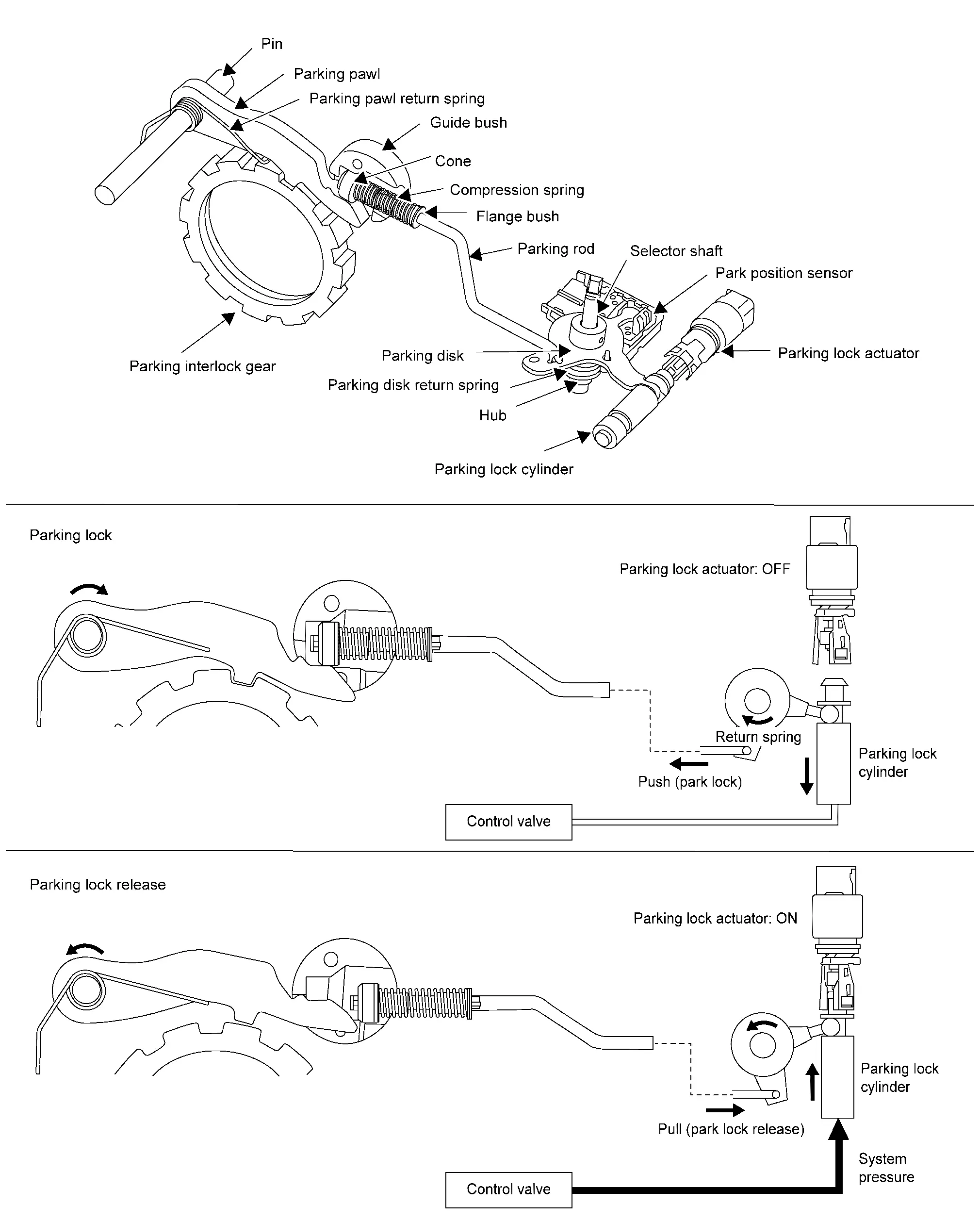
PARKING LOCK
In an automatic transmission, the parking lock takes on the function of the engaged gear in a manual transmission and secures the Nissan Pathfinder vehicle against rolling away unintentionally independent of any actuation of the parking brake. The most important components of the parking lock include the parking interlock gear, or actually its special gearing, and the parking lock pawl. When the parking lock is applied, the latter engages with the gearing of the parking interlock gear by a one-tooth segment. As the parking lock pawl in the transmission housing may be pivoted to a certain degree but is otherwise fixed, it blocks the parking interlock gear and thus the entire transmission.
Component Description
| Part | Function |
|---|---|
| Torque converter | Amplifies driving force the engine, and transmits it to transmission input shaft. |
| Oil pump | Driven by the engine, oil pump supplies oil to torque converter, control valve assembly, and each lubricating system. |
| Dog clutch A | Connects the input shaft and internal gear 1/sun gear 2. |
| Dog clutch F | Fastens the sun gear 3 and sun gear 4. |
| Clutch B | Connects the input shaft and sun gear 1. |
| Clutch E | Connects the input shaft and planetary carrier 3/internal gear 4. |
| Brake C | Fastens the sun gear 1. |
| Brake D | Fastens the internal gear 2. |
| Planeteary gear | Planetary gear set 1 and 2 are arranged they are overlapping. The internal gear of planetary gear set 1 and the sun gear of planetary gear set 2 are in a integral structure, and planetary carrier 1 and 2 that have four planetary pinions in their own respectively arecommon part. Planetary gear set 3 and 4 are arranged in parallel. The planetary carrier of the planetary gear set 3 and the internal gear of the planetary gear set 4 are in a integral structure and the sun gear of planetary gear set 3 and 4 are common part. |
| Parking lock cylinder | When system pressure is applied to the face end of the parking lock cylinder, the parking disk turns. And the parking rod that is linked to the parking disk rotates the parking pawl. When the parking pawl rotates, it engages with the parking gear, fixing the parking interlock gear. |
| Parking lock disc | |
| Parking rod | |
| Parking pawl | |
| Parking interlock gear |
Fluid Cooler System System Description
A/T FLUID COOLER SCHEMATIC (Without Tow Package)
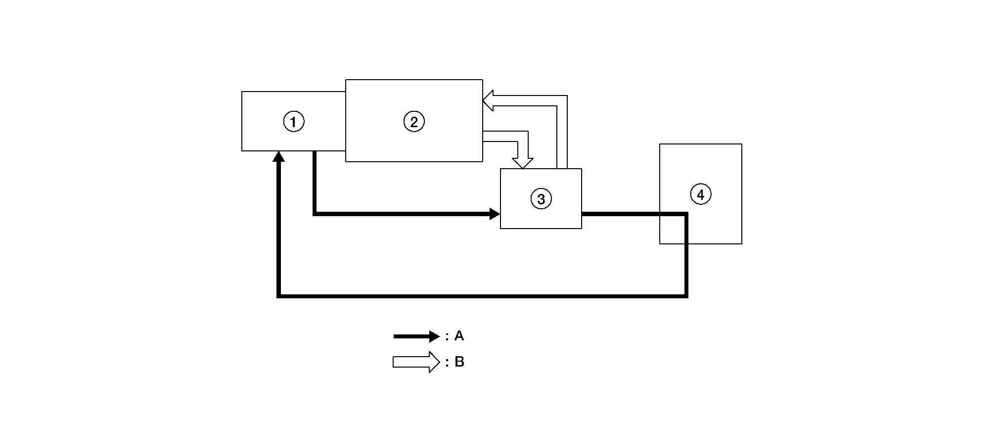
| 1. | Transaxle | 2. | Engine | 3. | A/T fluid warmer |
| 4. | Radiator | A. | A/T fluid | B. | Engine coolant |
A/T FLUID COOLER SCHEMATIC (With Tow Package)
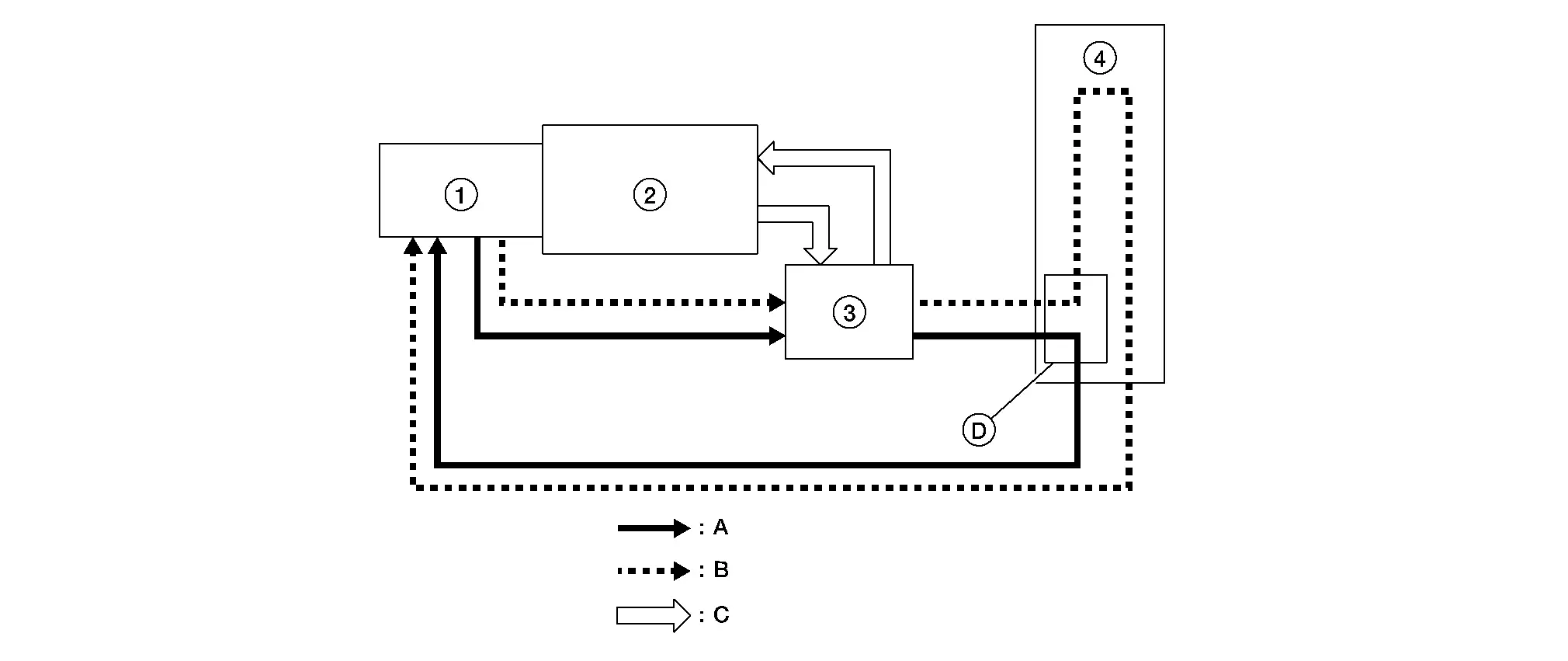
| 1. | Transaxle | 2. | Engine | 3. | A/T fluid warmer |
| 4. | A/T fluid cooler | A. | A/T fluid (Low temperature) | B. | A/T fluid (High temperature) |
| C. | Engine coolant | D. | Bypass valve |
COMPONENT DESCRIPTION
A/T Fluid Warmer
-
The A/T fluid warmer (1) is installed on the front part of transaxle assembly.
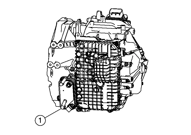
-
When engine is started while engine and A/T are cold, engine coolant temperature rises more quickly than A/T fluid temperature. A/T fluid warmer is provided with two circuits for A/T and engine coolant respectively so that warmed engine coolant warms A/T quickly. This helps shorten A/T warming up time, improving fuel economy.
-
A cooling effect is obtained when A/T fluid temperature is high.
A/T Fluid Cooler
-
A/T fluid cooler (1) is installed to condenser (2) and radiator (3).
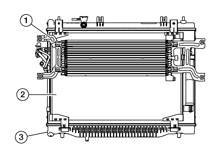
-
The A/T fluid cooler prevents A/T fluid temperature from an abnormal increase while driving the Nissan Pathfinder vehicle. When flowing into the A/T fluid cooler, A/T fluid is cooled by air stream caused by vehicle travel and returned to transmission.
Bypass Valve
-
The bypass valve (A) is part of the A/T fluid cooler.
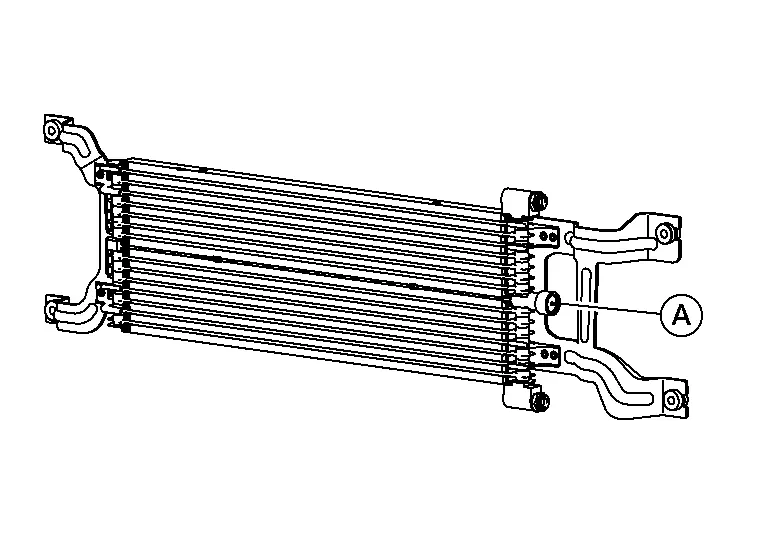
-
Bypass valve controls A/T fluid flow.
-
When A/T fluid temperature is low, the bypass valve is open. Most of A/T fluid therefore returns to the transaxle without flowing into the cooler core that has larger flow resistance.
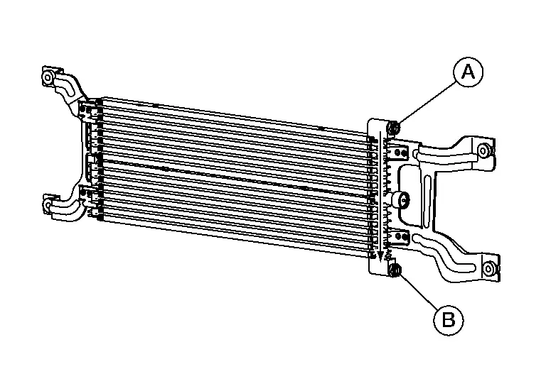
A. From A/T fluid warmer B. To transaxle -
When A/T fluid temperature rises [to approximately 60°C (140°F)], bypass valve fully closes and allows A/T fluid to flow into cooler core. A/T fluid flowing into cooler core is cooled by air stream caused by Nissan Pathfinder vehicle travel and returned to transaxle.
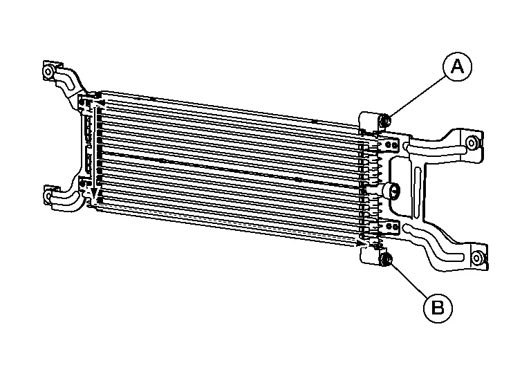
A. From A/T fluid warmer B. To transaxle

Nissan Pathfinder (R53) 2022-2026 Service Manual
Contact Us
Nissan Pathfinder Info Center
Email: info@nipathfinder.com
Phone: +1 (800) 123-4567
Address: 123 Pathfinder Blvd, Nashville, TN 37214, USA
Working Hours: Mon–Fri, 9:00 AM – 5:00 PM (EST)
