Nissan Pathfinder: Exterior - Removal and Installation
- Front Bumper
- Rear Bumper
- Front Grille
- Active Grille Shutter
- Cowl Top
- Roof Side Molding
- Door Outside Molding
- Rear Pillar Finisher (outer)
- Door Outside Lower Molding
- Rear Spoiler
- Back Door Outer Finisher
- Running Board
- Tow Hitch
- Emblem
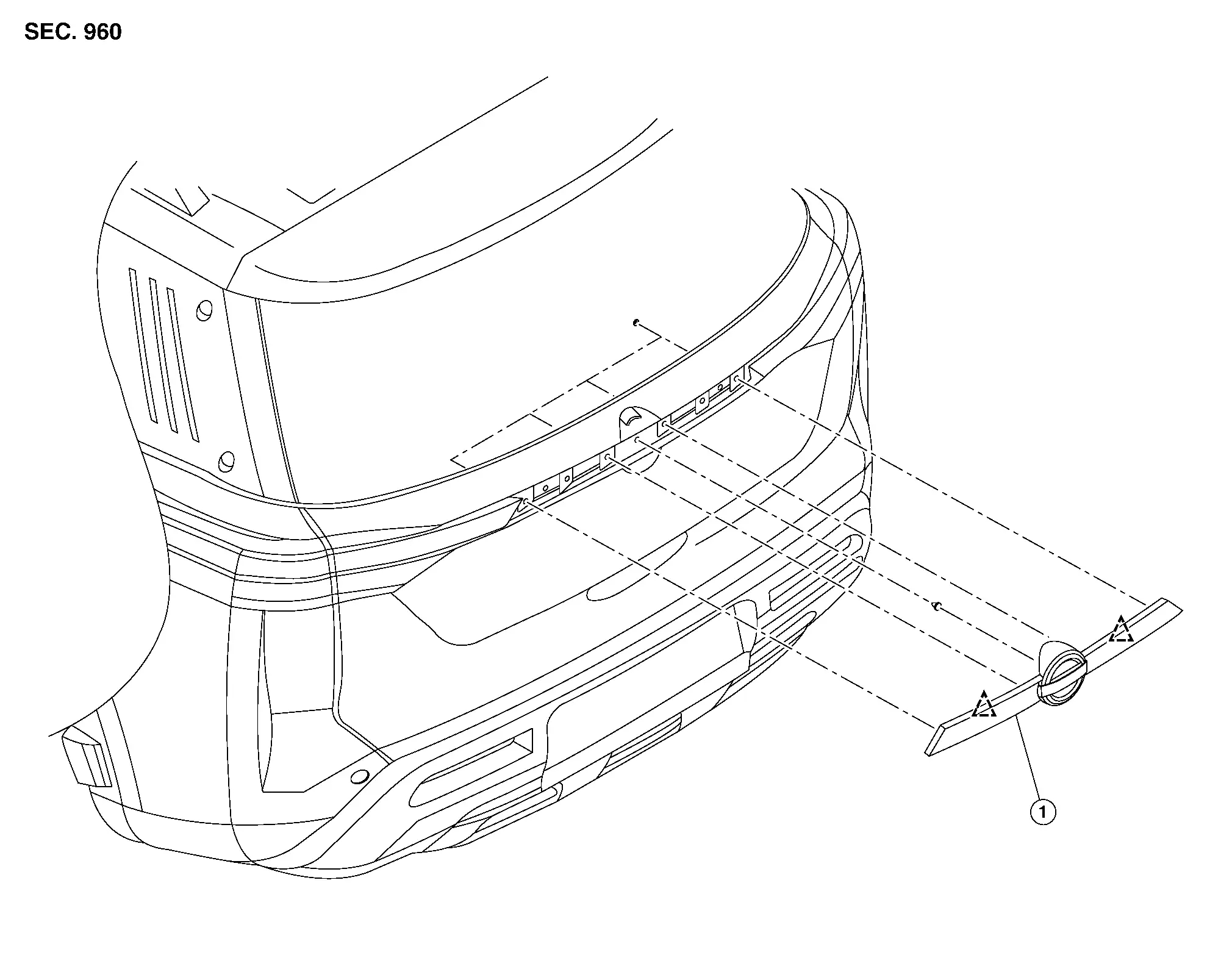
Front Bumper Nissan Pathfinder 5th Gen
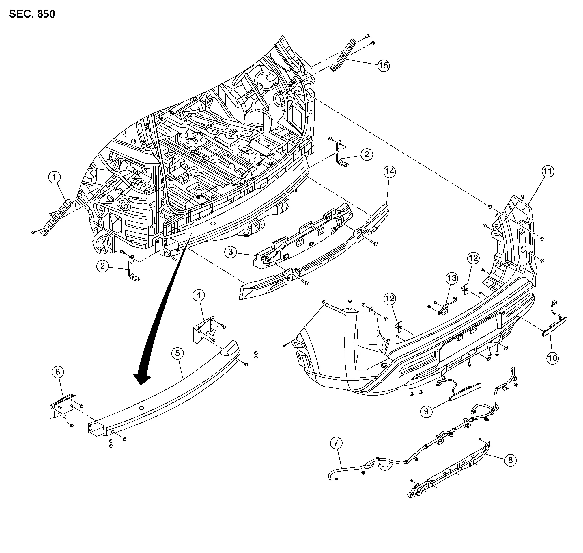
Exploded View
WITH ROCK CREEK®
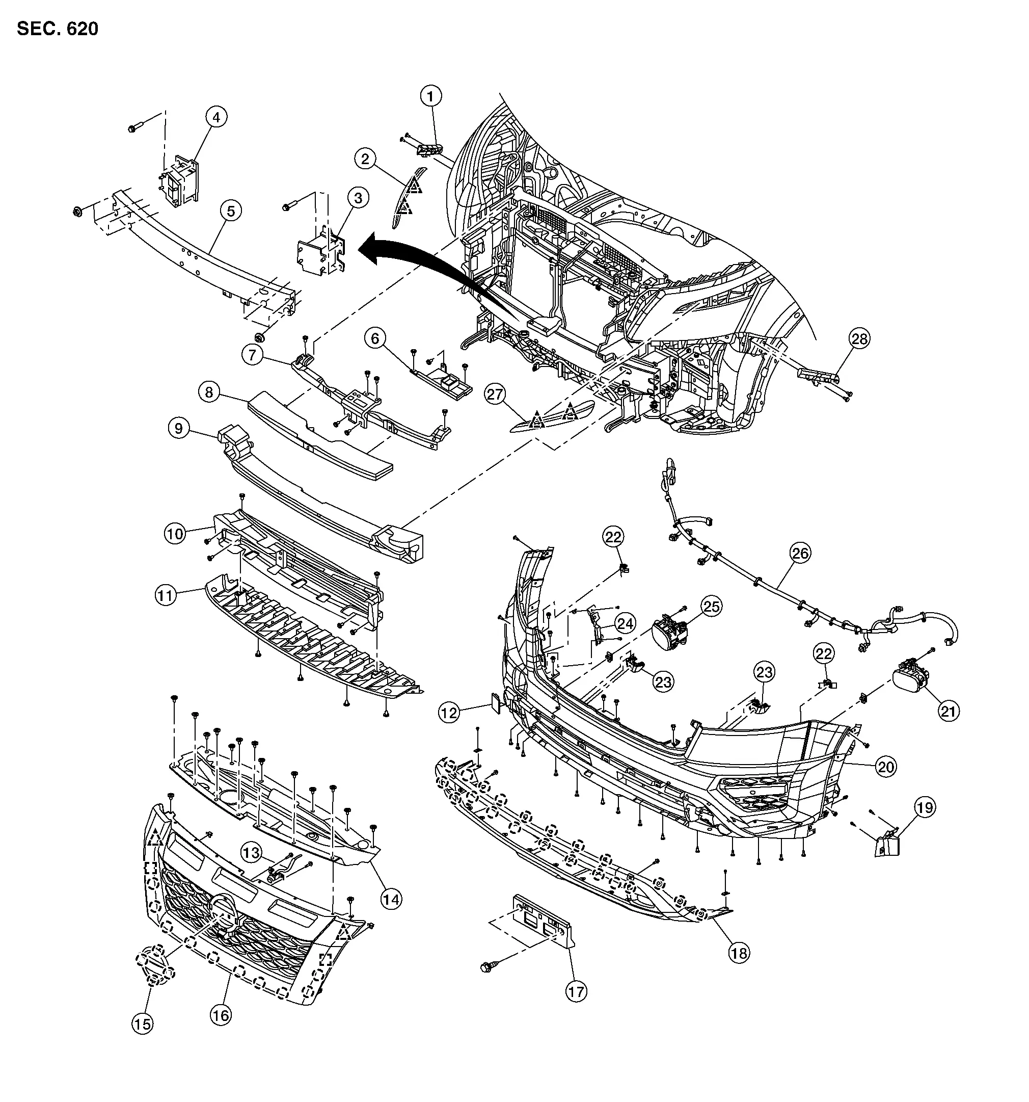
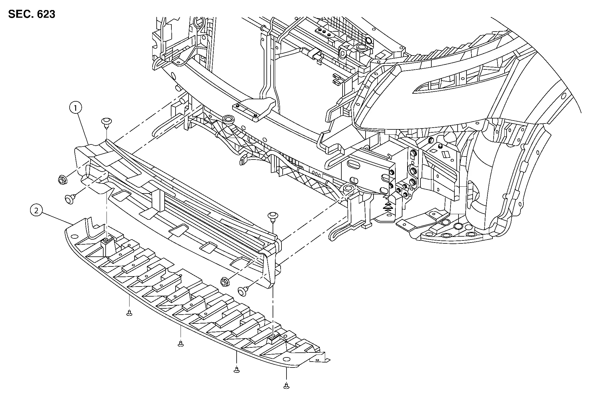
| 1. | Front bumper fascia side bracket (RH) | 2. | Grille molding (RH) | 3. | Front bumper reinforcement support (LH) |
| 4. | Front bumper reinforcement support (RH) | 5. | Front bumper reinforcement | 6. | Splash guard |
| 7. | Front bumper retainer | 8. | Front bumper energy absorber | 9. | Front bumper energy absorber (lower) |
| 10. | Active grille shutter | 11. | Apron bracket | 12. | Tow cover |
| 13. | Front camera | 14. | Core support cover | 15. | Emblem |
| 16. | Front grille | 17. | Front license plate bracket | 18. | Front bumper finisher |
| 19. | Side deflector (LH) | 20. | Front bumper fascia | 21. | Front fog lamp (LH) |
| 22. | Front sonar sensor | 23. | Front sonar sensor | 24. | Side deflector (RH) |
| 25. | Front fog lamp (RH) | 26. | Front bumper harness | 27. | Grille molding (LH) |
| 28. | Front bumper fascia side bracket (LH) |
 |
Pawl |
 |
Locator pin |
 |
Clip |
WITHOUT ROCK CREEK®
| 1. | Front bumper fascia side bracket (RH) | 2. | Grille molding (RH) | 3. | Front bumper reinforcement support (LH) |
| 4. | Front bumper reinforcement support (RH) | 5. | Front bumper reinforcement | 6. | Splash guard |
| 7. | Front bumper retainer | 8. | Front bumper energy absorber | 9. | Front bumper energy absorber (lower) |
| 10. | Active grille shutter | 11. | Apron bracket | 12. | Tow cover |
| 13. | Front camera | 14. | Core support cover | 15. | Emblem |
| 16. | Front grille | 17. | Front license plate bracket | 18. | Front air spoiler (upper) |
| 19. | Front sonar sensor | 20. | Front bumper fascia | 21. | Front sonar sensor |
| 22. | Fog lamp bracket (LH) | 23. | Fog lamp bracket (RH) | 24. | Front bumper finisher (LH) |
| 25. | Front fog lamp (LH) | 26. | Front fog lamp (RH) | 27. | Front bumper finisher (RH) |
| 28. | Front bumper harness | 29. | Grille molding (LH) | 30. | Front bumper fascia side bracket (LH) |
 |
Pawl |
 |
Locator Pin |
 |
Clip |
Removal and Installation
REMOVAL
CAUTION:
Front bumper fascia is made of resin. Use care when handling to prevent damage. Avoid contact with oily substances.
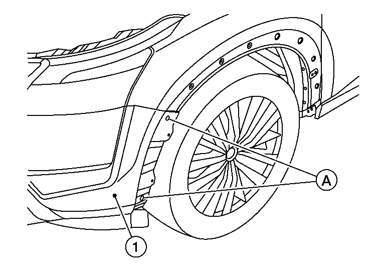
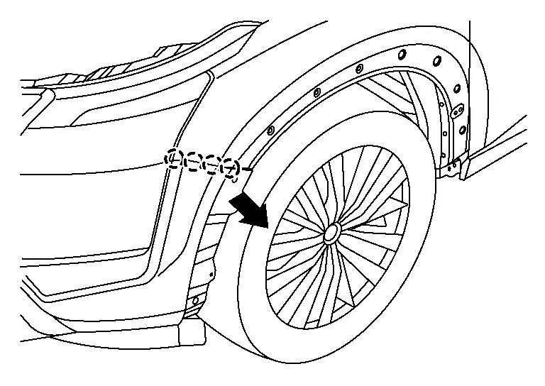
Remove front over fender (LH/RH). Refer to Removal and Installation.
Partially remove front fender protector (LH/RH). Refer to Removal and Installation.
Remove front grille. Refer to Removal and Installation.
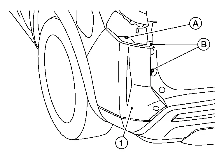
Remove clips (A) from front bumper fascia (1).
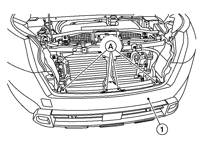
Remove side clips (A) from front bumper fascia [1 (LH/RH)].
Disconnect the harness connector from fog lamp [(LH/RH) (if so equipped)].
Remove lower fascia clips from front apron bracket. Refer to Exploded View.
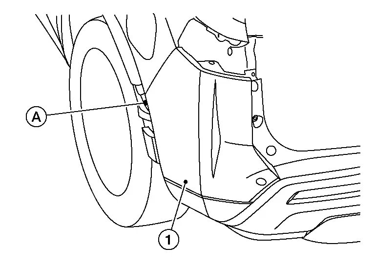
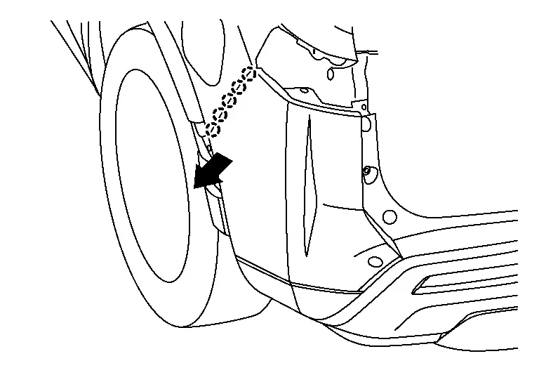
Pull front bumper fascia outward as shown, releasing pawls from front bumper fascia side bracket (LH/RH).
 |
: Pawl |
Remove the front bumper fascia.
CAUTION:
When removing front bumper fascia, two people are required to avoid damaging.
Remove the following parts (if necessary) after removing front bumper fascia:
-
Front fog lamp (LH/RH)
-
Front license plate bracket
-
Sonar sensors
-
Front bumper harness
-
Side deflector (LH/RH)
Remove front bumper energy absorbers.
 NOTE:
NOTE:
Use care when removing front bumper energy absorbers to prevent damage to the retaining tabs (avoid pulling with excess force and/or at an angle to avoid breakage).
INSTALLATION
Installation is in the reverse order of removal.
CAUTION:
-
Perform CALIBRATING CAMERA IMAGE (INTELLIGENT AROUND VIEW MONITOR). Refer to Work Procedure.
-
Perform “ADDITIONAL SERVICE WHEN REPLACING DISTANCE SENSOR (ICC SENSOR)” after front bumper installation. Refer to Work Procedure.
 NOTE:
NOTE:
-
The following table shows the specified values for checking normal installation status.
-
Fitting adjustment cannot be performed.
WITH ROCK CREEK®
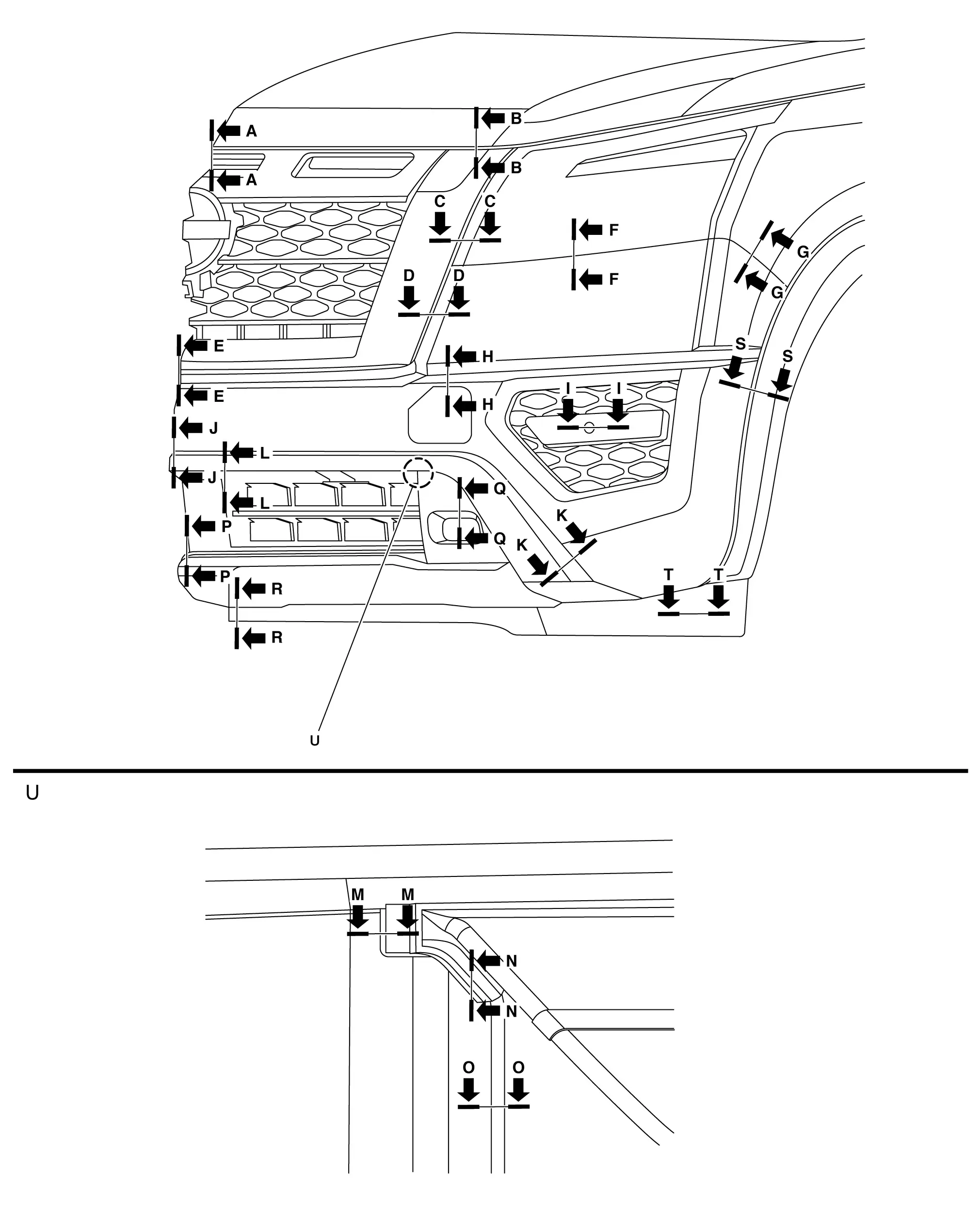
Unit: mm (in)
| Section | Measurement | Minimum | Target Value | Maximum |
|---|---|---|---|---|
| A-A | Clearance | 4.0 (0.16) | 6.0 (0.24) | 8.0 (0.32) |
| A-A | Surface height | -2.0 (-0.08) | 0.0 (0.00) | 2.0 (0.08) |
| B-B | Clearance | 4.0 (0.16) | 6.0 (0.24) | 8.0 (0.32) |
| B-B | Surface height | 3.5 (0.14) | 5.5 (0.21) | 7.5 (0.30) |
| C-C | Clearance | 1.3 (0.05) | 3.0 (0.12) | 4.7 (0.19) |
| D-D | Clearance | 0.7 (0.03) | 2.0 (0.08) | 3.3 (0.13) |
| E-E | Clearance | 0.2 (0.01) | 1.5 (0.06) | 2.8 (0.11) |
| F-F | Clearance | 0.3 (0.01) | 1.5 (0.06) | 2.7 (0.11) |
| G-G | Clearance | 0.1 (0.00) | 0.3 (0.01) | 1.1 (0.04) |
| G-G | Surface height | -1.5 (-0.06) | –0.5 (–0.02) | 1.5 (0.06) |
| H-H | Clearance | 0.0 (0.00) | 0.5 (0.02) | 1.0 (0.04) |
| H-H | Surface height | -0.8 (0.03) | –0.3 (–0.01) | 0.2 (0.01) |
| I-I | Clearance | 0.1 (0.00) | 0.4 (0.02) | 0.7 (0.03) |
| I-I | Surface height | 0.0 (0.00) | 0.5 (0.01) | 1.0 (0.04) |
| J-J | Clearance | 0.0 (0.00) | 0.5 (0.02) | 1.0 (0.04) |
| K-K | Clearance | 0.7 (0.03) | 1.2 (0.05) | 2.4 (0.09) |
| L-L | Clearance | 0.0 (0.00) | 0.5 (0.02) | 1.5 (0.06) |
| L-L | Surface height | -0.2 (0.01) | 1.0 (0.04) | 1.5 (0.06) |
| M-M | Clearance | 1.8 (0.07) | 3.0 (0.12) | 4.2 (0.17) |
| M-M | Surface height | -1.0 (-0.04) | 0.0 (0.00) | 1.0 (0.04) |
| N-N | Clearance | 0.0 (0.00) | 0.5 (0.02) | 1.5 (0.06) |
| N-N | Surface height | -0.7 (-0.03) | 0.5 (0.02) | 1.0 (0.04) |
| O-O | Clearance | 0.0 (0.00) | 0.5 (0.02) | 1.5 (0.06) |
| O-O | Surface height | 0.5 (0.02) | 1.0 (0.04) | 2.2 (0.09) |
| P-P | Clearance | 0.0 (0.00) | 0.8 (0.03) | 1.6 (0.06) |
| Q-Q | Clearance | 0.5 (0.02) | 2.0 (0.08) | 3.5 (0.14) |
| R-R | Clearance | 0.0 (0.00) | 0.5 (0.02) | 1.5 (0.06) |
| S-S | Clearance | 0.0 (0.00) | 0.5 (0.02) | 1.5 (0.06) |
| T-T | Clearance | 0.0 (0.00) | 0.5 (0.02) | 1.0 (0.04) |
| T-T | Surface height | -1.0 (-0.04) | 0.0 (0.00) | 1.0 (0.04) |
WITHOUT ROCK CREEK®
Unit: mm (in)
| Section | Measurement | Minimum | Target Value | Maximum |
|---|---|---|---|---|
| A-A | Clearance | 4.0 (0.16) | 6.0 (0.24) | 8.0 (0.32) |
| A-A | Surface height | -2.0 (-0.08) | 0.0 (0.00) | 2.0 (0.08) |
| B-B | Clearance | 0.2 (0.01) | 1.5 (0.06) | 2.8 (0.11) |
| B-B | Surface height | 0.0 (0.00) | 0.0 (0.00) | 0.0 (0.00) |
| C-C | Clearance | 0.0 (0.00) | 0.5 (0.02) | 1.5 (0.06) |
| D-D | Surface height | 0.0 (0.00) | 0.5 (0.02) | 1.5 (0.06) |
| E-E | Clearance | 0.1 (0.00) | 0.3 (0.01) | 1.1 (0.04) |
| E-E | Surface height | -0.5 (-0.02) | 0.5 (0.02) | 1.5 (0.06) |
| F-F | Clearance | 0.0 (0.00) | 0.0 (0.00) | 0.7 (0.03) |
| G-G | Clearance | 0.0 (0.00) | 1.0 (0.04) | 2.0 (0.08) |
| H-H | Clearance | 0.5 (0.02) | 2.0 (0.08) | 3.5 (0.13) |
| J-J | Clearance | -1.3 (0.05) | 3.0 (0.12) | 4.7 (0.19) |
| J-J | Surface height | 0.0 (0.00) | 0.0 (0.00) | 0.0 (0.00) |
| K-K | Clearance | 0.1 (0.00) | 0.4 (0.01) | 0.7 (0.03) |
| K-K | Surface height | 0.0 (0.00) | 0.5 (0.02) | 1.0 (0.04) |
| L-L | Clearance | 0.2 (0.01) | 1.0 (0.04) | 1.8 (0.07) |
| L-L | Surface height | -0.8 (-0.03) | -0.4 (-0.02) | 0.0 (0.00) |
| M-M | Clearance | 0.3 (0.01 | 1.5 (0.06) | 2.7 (0.11) |
| M-M | Surface height | 0.0 (0.00) | 0.0 (0.00) | 0.0 (0.00) |
| N-N | Clearance | 0.1 (0.00) | 1.5 (0.06) | 2.9 (0.11) |
| P-P | Clearance | 0.1 (0.00) | 1.5 (0.06) | 2.9 (0.11) |
| Q-Q | Clearance | 0.1 (0.00) | 1.5 (0.06) | 2.9 (0.11) |
| Q-Q | Surface height | -1.2 (-0.05) | 0.0 (0.00) | 1.2 (0.05) |
| R-R | Clearance | 0.1 (0.00) | 1.5 (0.06) | 2.9 (0.11) |
| S-S | Clearance | 0.0 (0.00) | 0.5 (0.02) | 1.0 (0.04) |
| S-S | Surface height | -0.2 (-0.01) | 0.3 (0.01) | 0.8 (0.03) |
| T-T | Clearance | 4.0 (0.16) | 6.0 (0.24) | 8.0 (0.32) |
| T-T | Surface height | 3.5 (0.14) | 5.5 (0.21) | 7.5 (0.30) |
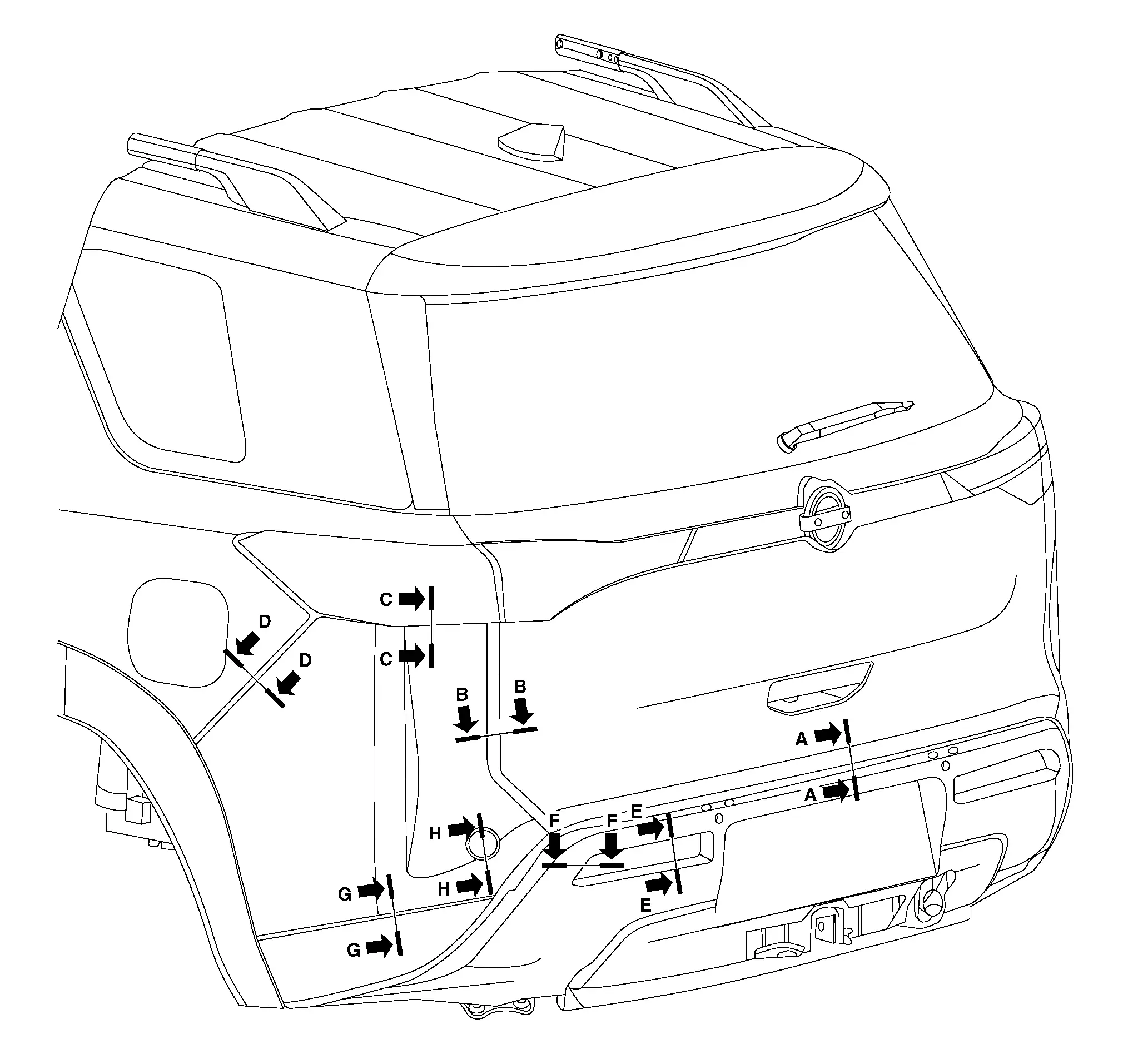
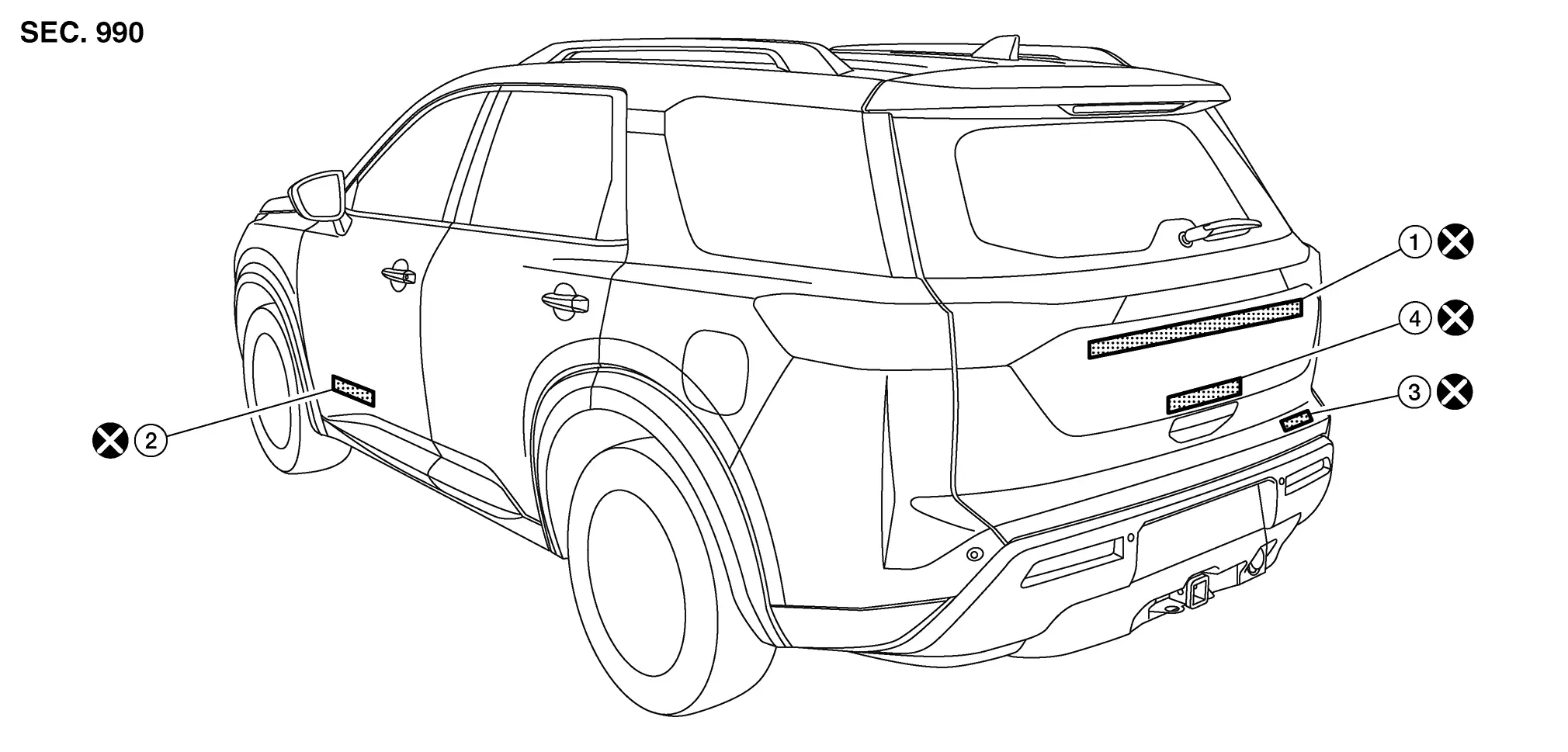
Rear Bumper Nissan Pathfinder R53
Exploded View
| 1. | Rear bumper side bracket (LH) | 2. | Rear bumper lower retainer (LH) | 3. | Rear bumper energy absorber |
| 4. | Rear bumper reinforcement support (RH) | 5. | Rear bumper reinforcement | 6. | Rear bumper reinforcement support (LH) |
| 7. | Rear bumper harness | 8. | Rear bumper stiffener | 9. | Reflector (LH) |
| 10. | Reflector (RH) | 11. | Rear bumper fascia | 12. | Rear sonar sensor |
| 13. | Rear view camera | 14. | Rear bumper energy absorber (lower) | 15. | Rear bumper side bracket (RH) |
Removal and Installation
REMOVAL
CAUTION:
Rear bumper fascia is made of resin. Use care when handling to prevent damage. Avoid contact with oily substances.
Open back door.
Remove rear combination lamp (LH/RH). Refer to Removal and Installation.
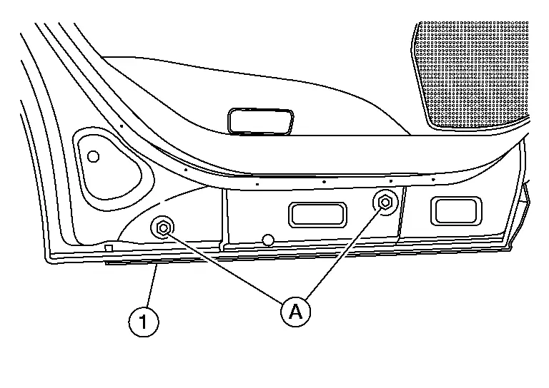
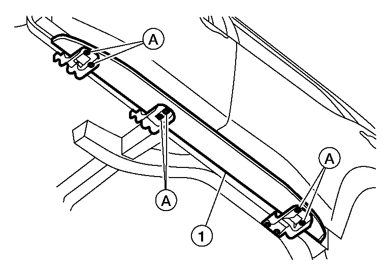
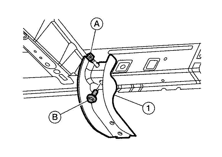
Remove upper clips (A) and screws (B) from rear bumper fascia [1 (LH/RH)].
Remove rear over fender [body side (LH/RH)]. Refer to Removal and Installation.
Remove screw (A) from rear bumper fascia [1 (LH/RH)].
Remove lower clips (A) from rear bumper fascia (1).
Disconnect rear bumper harness (RH).
Pulling outward as shown, release rear bumper fascia pawls from rear bumper fascia side bracket (LH/RH).
 |
: Pawl |
Remove the rear bumper fascia.
CAUTION:
When removing rear bumper fascia, two people are required to avoid damaging.
Remove the following parts (if necessary) after removing rear bumper fascia:
-
Rear bumper side bracket (LH/RH)
-
Rear bumper fascia reflector (LH/RH)
-
Rear sonar sensors
-
Rear view camera
-
Rear bumper harness
-
Hands free sensor
Remove rear bumper energy absorbers.
INSTALLATION
Installation is in the reverse order of removal.
CAUTION:
After installation, perform the following action tests to confirm proper system operation:
-
Blind Spot Warning (BSW): Refer to Work Procedure.
-
Rear Cross Traffic Alert (RCTA): Refer to Work Procedure.
Perform CALIBRATING CAMERA IMAGE (INTELLIGENT AROUND VIEW MONITOR). Refer to Work Procedure.
 NOTE:
NOTE:
-
The following table shows the specified values for checking normal installation status.
-
Fitting adjustment cannot be performed.
mm (in)
| Section | Measurement | Minimum | Target Value | Maximum |
|---|---|---|---|---|
| A-A | Clearance | 4.9 (0.19) | 7.0 (0.28) | 9.1 (0.36) |
| B-B | Clearance | 3.0 (0.12) | 5.0 (0.20) | 7.0 (0.28) |
| B-B | Surface height | -1.0 (0.04) | 1.0 (0.04) | 3.0 (0.12) |
| C-C | Clearance | 0.0 (0.00) | 1.5 (0.06) | 3.0 (0.12) |
| D-D | Clearance | 0.0 (0.00) | 0.3 (0.01) | 1.1 (0.04) |
| D-D | Surface height | -0.2 (0.00) | 0.8 (0.03) | 1.8 (0.07) |
| E-E | Clearance | 0.0 (0.00) | 1.0 (0.04) | 2.0 (0.08) |
| F-F | Clearance | 0.0 (0.00) | 1.0 (0.04) | 2.0 (0.08) |
| G-G | Clearance | 0.0 (0.00) | 0.0 (0.00) | 0.5 (0.02) |
| H-H | Clearance | 0.1 (0.00) | 0.4 (0.02) | 0.7 (0.03) |
| H-H | Surface height | 0.0 (0.00) | 0.5 (0.02) | 1.0 (0.04) |
Front Grille Nissan Pathfinder R53
Exploded View
WITH ROCK CREEK®
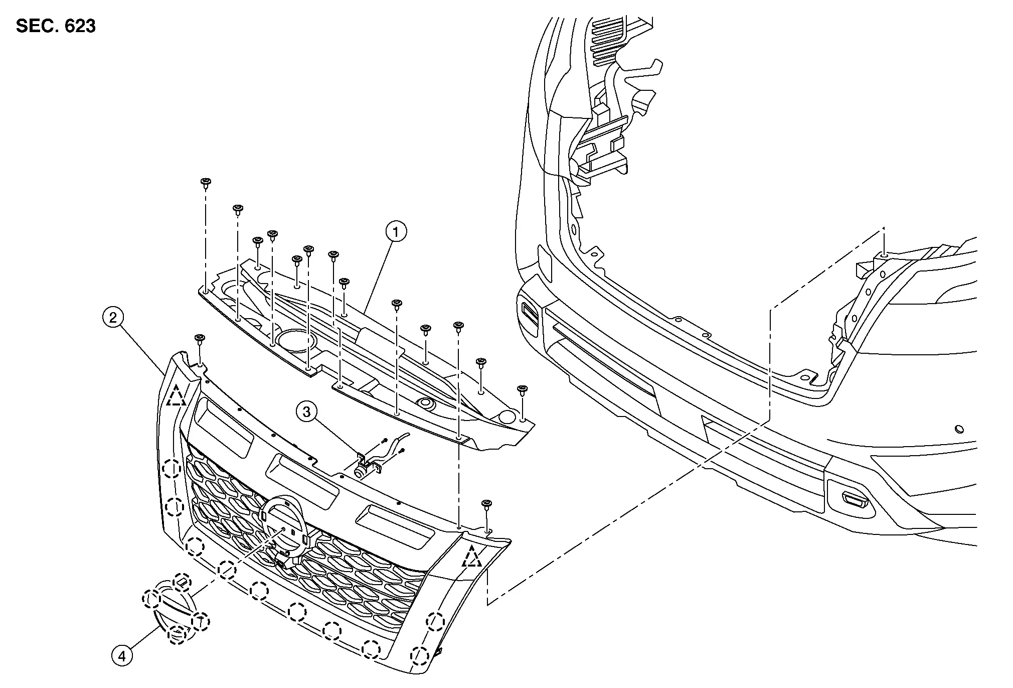
| 1. | Core support cover | 2. | Front grille | 3. | Front camera |
| 4. | Emblem |
 |
Clip |
 |
Pawl |
WITHOUT ROCK CREEK®
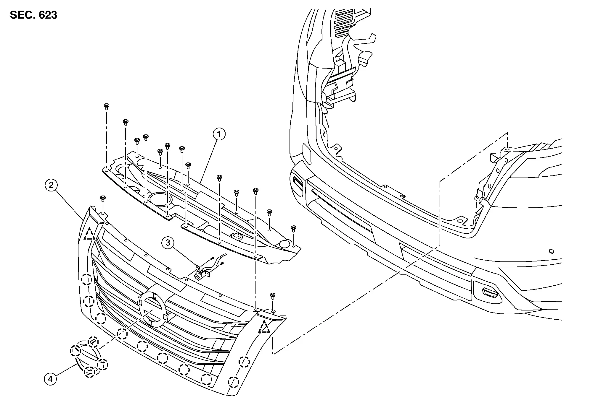
| 1. | Core support cover | 2. | Front grille | 3. | Front camera |
| 4. | Emblem |
 |
Clip |
 |
Pawl |
Removal and Installation
REMOVAL
Open hood.
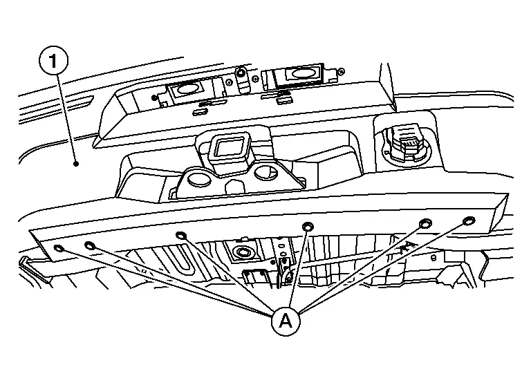
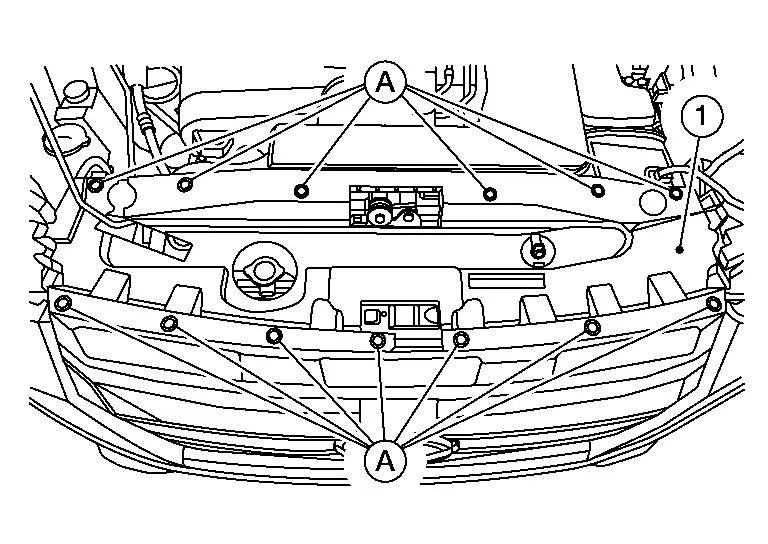
Remove clips (A) and core support cover (1).
Disconnect the harness connector from front camera (if equipped).
Remove upper clips (A) from front grille (1).
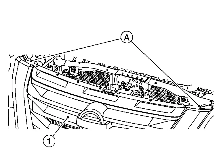
Release pawls and remove front grille. Refer to Exploded View.
If necessary, remove the following parts from front grille:
-
Front emblem
-
Front camera
INSTALLATION
Installation is in the reverse order of removal.
CAUTION:
Perform CALIBRATING CAMERA IMAGE (INTELLIGENT AROUND VIEW MONITOR). Refer to Work Procedure.
Active Grille Shutter Nissan Pathfinder 2022
Exploded View
| 1. | Active grille shutter | 2. | Apron bracket |
Removal and Installation
REMOVAL
Remove front bumper fascia. Refer to Removal and Installation.
Remove active grille shutter nuts and clips. Refer to Exploded View.
Disconnect harness connector and remove active grille shutter.
INSTALLATION
Installation is in the reverse order of removal.
Cowl Top Nissan Pathfinder 5th Gen
Exploded View
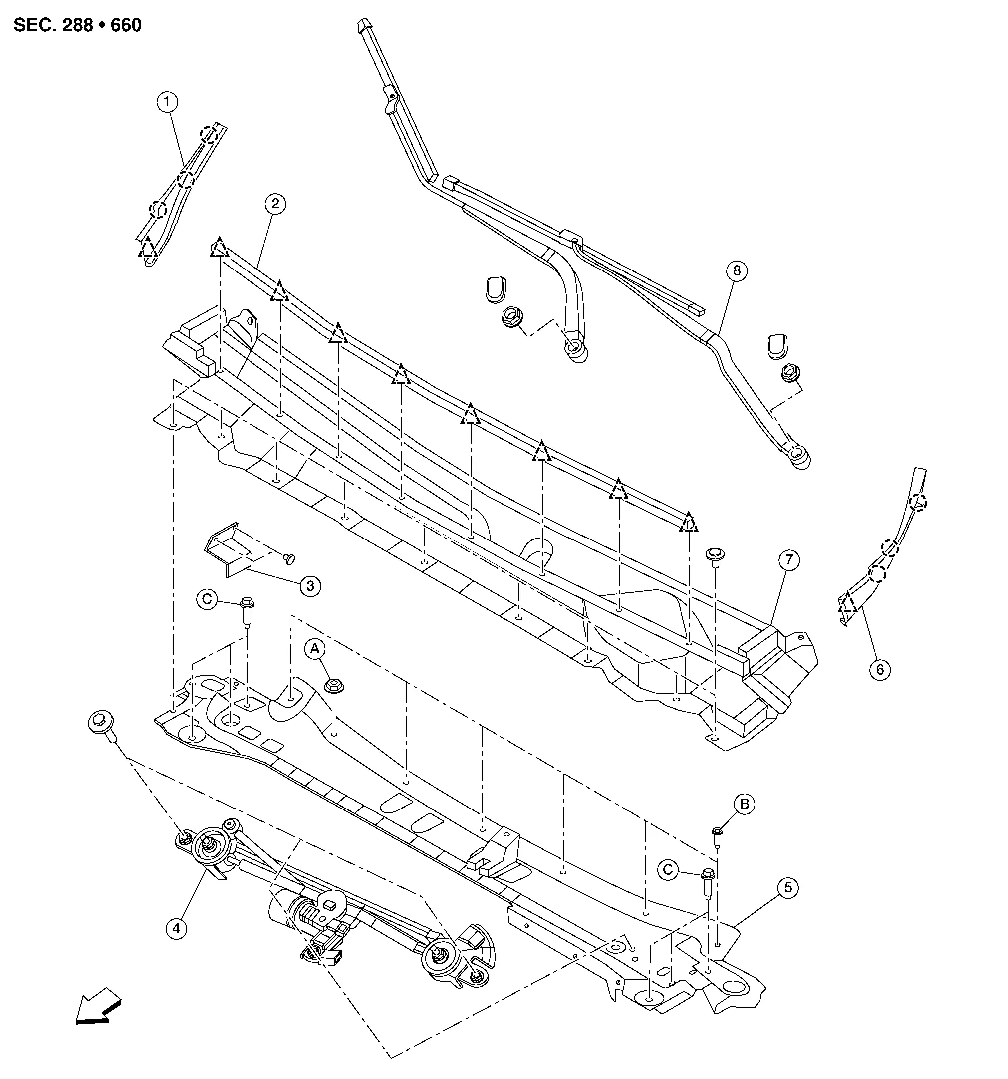
| 1. | Cowl top side trim cover (RH) | 2. | Cowl top seal | 3. | Air intake bracket |
| 4. | Front wiper drive assembly | 5. | Cowl top extension | 6. | Cowl top side trim cover (LH) |
| 7. | Cowl top cover | 8. | Front wiper arm | A. | Refer to Installation. |
| B. | Refer to Installation. | C. | Refer to Installation. |
 |
Clip |
 |
Pawl |
 |
Front |
Removal and Installation
COWL TOP COVER
REMOVAL
Remove front wiper arm (LH/RH). Refer to Removal and Installation.
Remove cowl top cover clips. Refer to Exploded View.
Pull cowl top cover forward to release and remove from Nissan Pathfinder vehicle.
CAUTION:
When performing any procedure after removing cowl top cover, protect the lower end of windshield glass with urethane etc.
Using suitable tool, release clips and remove cowl top seal (if necessary). Refer to Exploded View.
INSTALLATION
Installation is in the reverse order of removal.
CAUTION:
-
When installing cowl top cover, check that clips are securely placed in panel holes on body and then press them in.
-
After installation, perform WIPER BLADE POSITION ADJUSTMENT. Refer to Adjustment.
COWL TOP EXTENSION
REMOVAL
Remove the front wiper drive assembly. Refer to Removal and Installation.
CAUTION:
When performing any procedure after removing cowl top cover, protect the lower end of windshield glass with urethane etc.
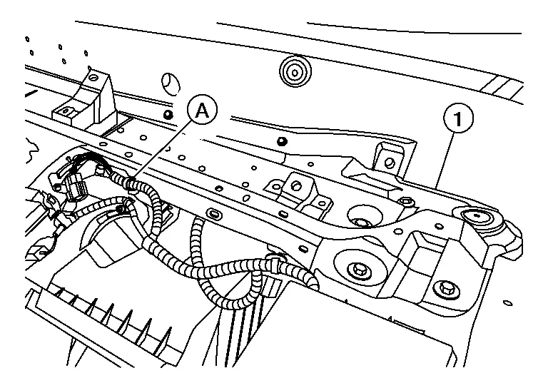
Separate harness retainer (A) from cowl top extension (1).
Remove the nuts and separate the reservoir tank bracket from the cowl top extension. Refer to Exploded View.
Remove bolts and cowl top extension. Refer to Exploded View.
INSTALLATION
Installation is in the reverse order of removal.
-
Install cowl top extension (1) with nut (A) finger tight, then install bolts (B) and bolts (C) finger tight.
-
Tighten nut (A) first, then bolts (B) and bolts (C) to specification:
Nut (A) : 7.0 Nm (0.71 kg-m, 62 in-lb) Bolts (B) : 5.5 Nm (0.56 kg-m, 49 in-lb) Bolts (C) : 35.0 Nm (3.6 kg-m, 26 ft-lb)
CAUTION:
-
When installing cowl top cover, check that clips are securely placed in panel holes on body and then press them in.
-
After installation, perform WIPER BLADE POSITION ADJUSTMENT. Refer to Adjustment.
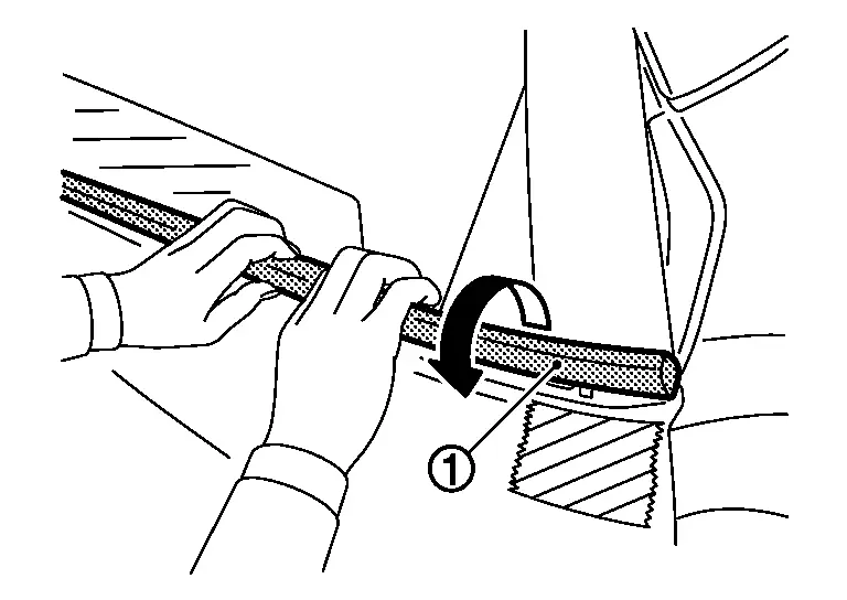
Roof Side Molding Nissan Pathfinder Fifth generation
Exploded View
 NOTE:
NOTE:
LH shown, RH similar.
| 1. | Roof side molding | 2. | Back door hinge cover |
 |
Clip |
 |
Pawl |
Removal and Installation
REMOVAL
Using suitable tool (A), release roof side molding clips. Refer to Exploded View.
CAUTION:
Apply protective tape (B) around the roof side molding.
 |
: Clip |
Remove roof side molding.
INSTALLATION
Installation is in the reverse order of removal.
CAUTION:
When installing, make sure all clips are on roof side molding. Make sure all old clips have been removed from posts on roof panel.
Door Outside Molding Nissan Pathfinder
Exploded View
 NOTE:
NOTE:
LH shown, RH similar.
| 1. | Front door outside molding | 2. | Rear door outside molding |
 |
Pawl |
Removal and Installation
FRONT DOOR OUTSIDE MOLDING
REMOVAL
Rotate and lift as shown to remove the front door outside molding (1).
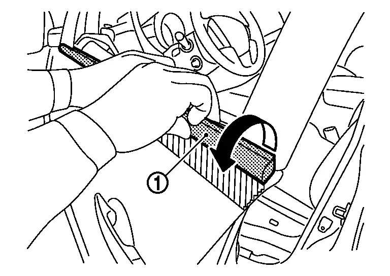
CAUTION:
-
Apply protective tape on front door panel.
-
Do not use excessive force when removing or damage may occur.
INSTALLATION
Installation is in the reverse order of removal.
REAR DOOR OUTSIDE MOLDING
REMOVAL
Rotate and lift as shown to remove the rear door outside molding (1).
CAUTION:
-
Apply protective tape on rear door panel.
-
Do not use excessive force when removing or damage may occur.
INSTALLATION
Installation is in the reverse order of removal.
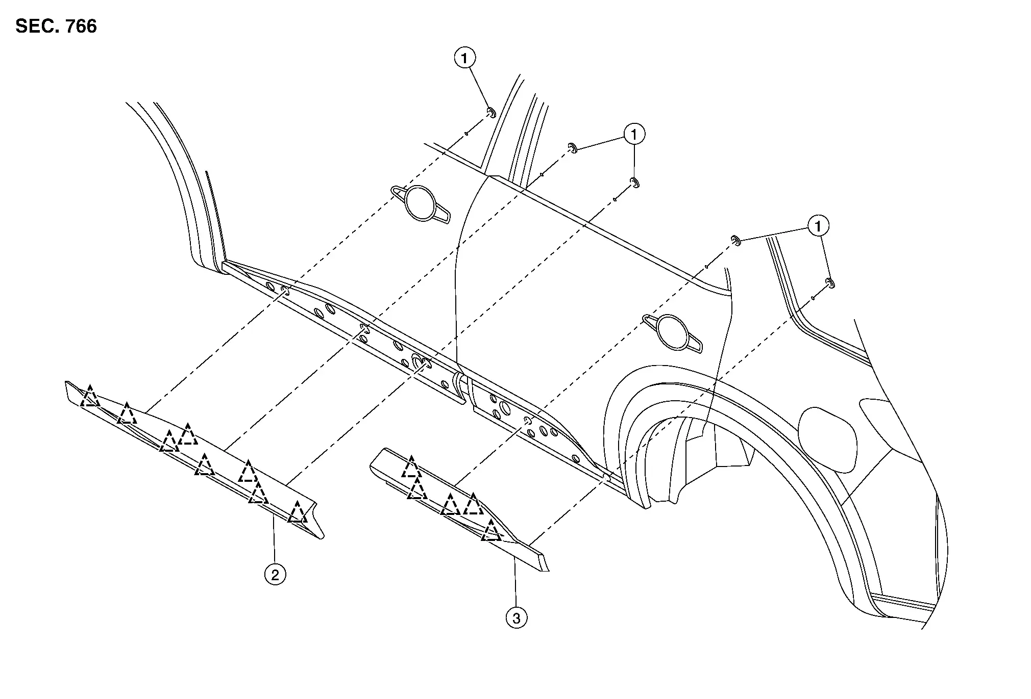
Rear Pillar Finisher (outer) Nissan Pathfinder
Exploded View
| 1. | Rear pillar finisher (outer) | 2. | Body side outer | A. | Adhesive tape |
 |
Clip |
 NOTE:
NOTE:
LH shown, RH similar.
Removal and Installation
REMOVAL
Using suitable tool, release clips and adhesive tape. Refer to Exploded View.
Remove rear pillar finisher (outer).
INSTALLATION
Installation is in the reverse order of removal.
CAUTION:
-
Clean mounting area before installation.
-
Do not reuse adhesive tape.
Door Outside Lower Molding Nissan Pathfinder 2026
Exploded View
 NOTE:
NOTE:
LH shown, RH similar.
| 1. | Plug | 2. | Front door outside lower molding (LH) | 3. | Rear door outside lower molding (LH) |
 |
Clip |
Removal and Installation
FRONT DOOR OUTSIDE LOWER MOLDING
Removal
Remove plugs (1) from front door inner panel (2).
Remove front door outside lower molding nuts (A) from front door (1).
Using suitable tool, release clips and remove front door outside lower molding.
 |
: Clip |
Installation
Installation is in the reverse order of removal.
CAUTION:
-
When installing, visually check front door outside lower molding and clips. Replace with new parts if they have been damaged.
-
When installing front door outside lower molding, make sure that the clips are attached to the molding. Make sure all old clips have been removed from door.
REAR DOOR OUTSIDE LOWER MOLDING
REMOVAL
Remove plugs (1) from rear door inner panel (2).
Remove rear door outside lower molding nuts (A) from rear door (1).
Using suitable tool, release clips and remove rear door outside lower molding.
 |
: Clip |
INSTALLATION
Installation is in the reverse order of removal.
CAUTION:
-
When installing, visually check rear door outside lower molding and clips. Replace with new parts if they have been damaged.
-
When installing rear door outside lower molding, make sure that the clips are attached to the molding. Make sure all old clips have been removed from door.
-
Make sure all old double sided tape residue is removed from door.
-
When installing lower door molding, make sure to wipe clean metal surface and apply sufficient force to attach double sided tape.
Rear Spoiler Nissan Pathfinder 2026
Exploded View
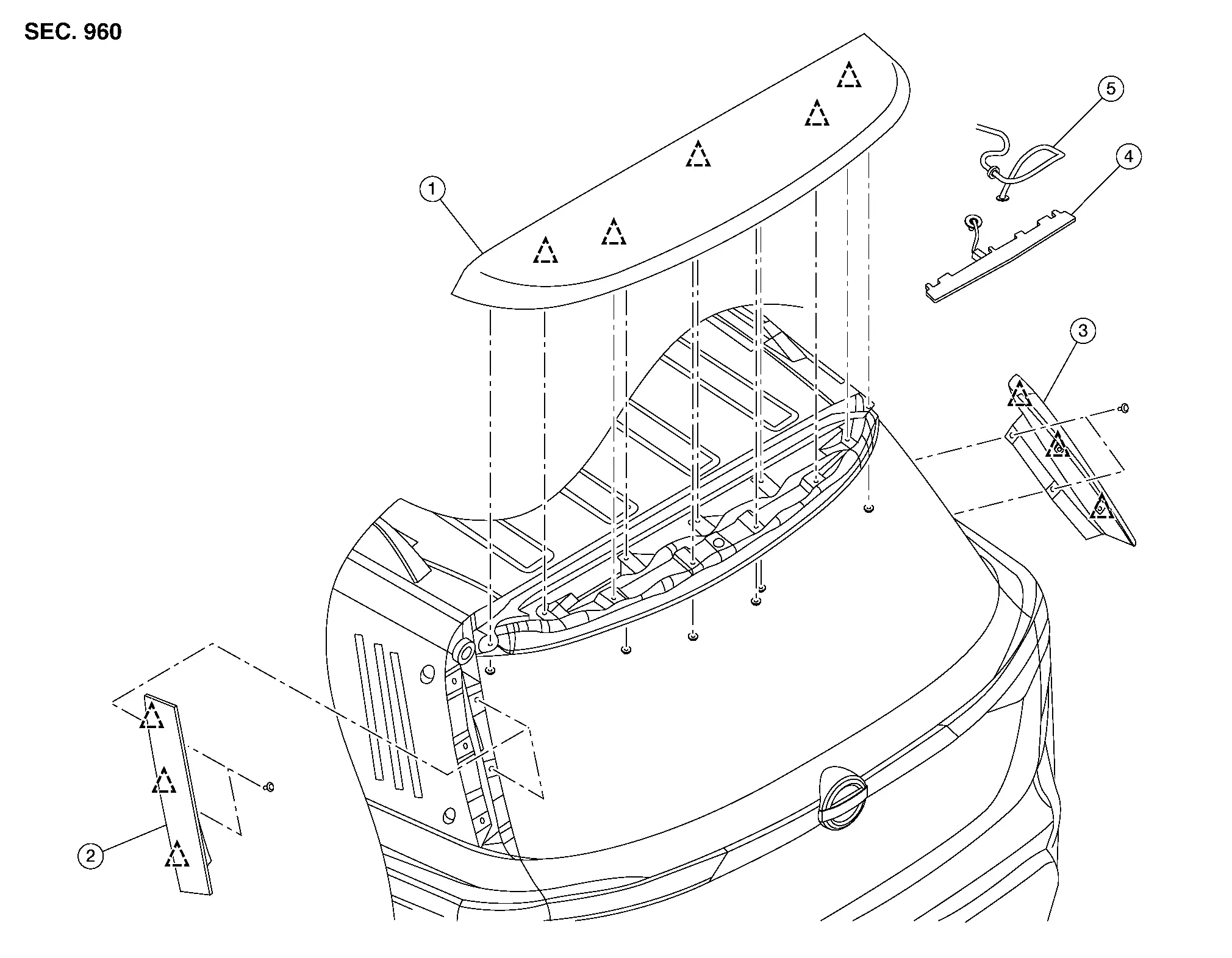
| 1. | Rear spoiler | 2. | Rear spoiler side trim cover (LH) | 3. | Rear spoiler side trim cover (RH) |
| 4. | High-mounted stop lamp | 5. | Rear washer nozzle |
 |
Clip |
Removal and Installation
REMOVAL
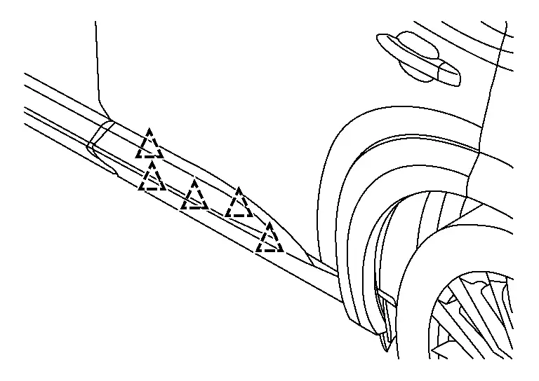
Remove back door upper finisher. Refer to Removal and Installation.
Remove the rear spoiler nuts. Refer to Exploded View.
Disconnect the harness connector from high-mounted stop lamp.
Release the rear washer nozzle tube.
Release the rear spoiler clips with a suitable tool (A), and then remove the rear spoiler.
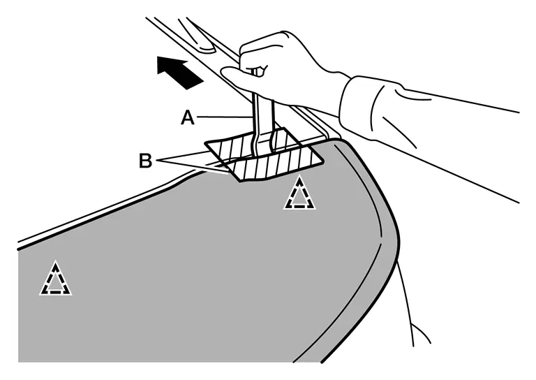
CAUTION:
Apply protective tape (B) to the roof panel and rear spoiler to protect the painted surface from damage.
 |
: Clip |
Remove following parts (if necessary) after removing rear spoiler:
-
High-mounted stop lamp
-
Rear spoiler side trim covers (LH/RH)
-
Rear washer nozzle
INSTALLATION
Installation is in the reverse order of removal.
CAUTION:
-
When installing, visually check the rear spoiler and the clips and replace them with new parts if they are damaged.
-
When installing, make sure that the clips and bolts are securely placed in back door panel holes, and then press them in.
-
Do not wash the Nissan Pathfinder vehicle within 24 hours after installing to allow adhesive time to cure.
Back Door Outer Finisher Nissan Pathfinder Fifth generation
Exploded View
| 1. | Back door outer finisher |
 |
Clip |
Removal and Installation
REMOVAL
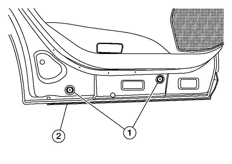
Remove the back door lower finisher. Refer to Removal and Installation.
Disconnect the harness connectors from rear view camera (if equipped) and back door opener switch.
Remove the back door outer finisher nuts. Refer to Exploded View.
Using suitable tool, release clips and remove back door outer finisher. Refer to Exploded View.
Remove the back door opener switch (if necessary).
INSTALLATION
Installation is in the reverse order of removal.
Running Board Nissan Pathfinder
Removal and Installation
REMOVAL
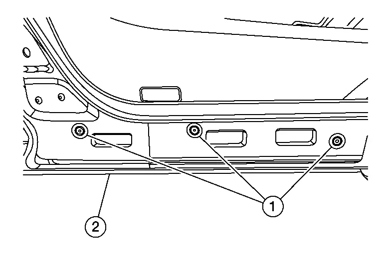
Remove running board bolts (A) and running board (1).
Remove running board bracket nut (A), bolt (B), and running board bracket (front, center, and rear).
| (1) | : Running board bracket (front, center, and rear) |
INSTALLATION
 NOTE:
NOTE:
For new installation, perform Steps 1–4.
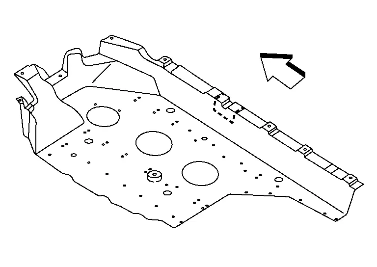
Remove floor under cover (LH). Refer to Removal and Installation.
Using suitable tool, cut notch in floor under cover (LH) as shown.
 |
: Front |
Remove floor under cover (RH). Refer to Removal and Installation.
Using suitable tool, cut notch in floor under cover (RH) as shown.
 |
: Front |
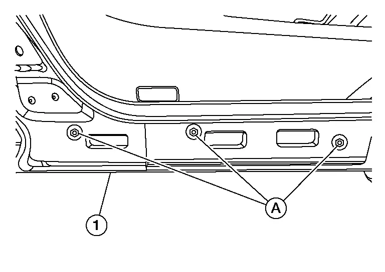
Locate running board bracket mounting holes and studs on underbody. Clean threads of holes and studs if necessary.
Install front, center, and rear running board brackets (1) to underbody with nut (A) and bolt (B) finger tight.

Install floor under covers. Refer to Removal and Installation.
Install running board to running board brackets with bolts finger tight.
 NOTE:
NOTE:
Running boards are LH/RH specific.
Tighten running board bracket nuts to specification:
| Nuts | : 14 N-m (10 ft-lb) |
Tighten running board bracket bolts to specification:
| Bolts | : 24 N-m (18 ft-lb) |
Tighten running board bolts to specification.
| Bolts | : 14 N-m (10 ft-lb) |
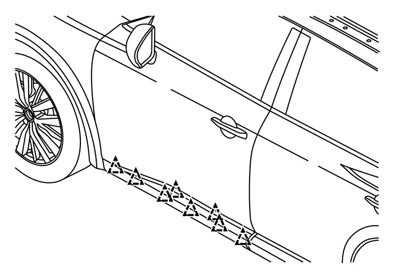
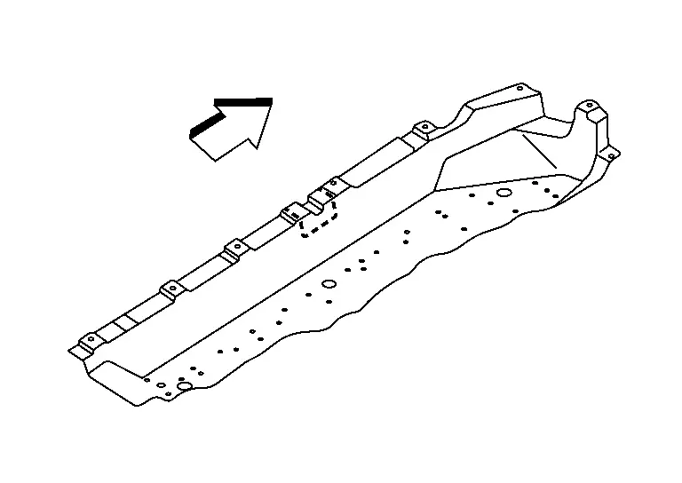
Using suitable tool, release clips and remove door parting seal (1) from sill (2).
CAUTION:
Plastic clips may break during removal. Verify broken clips are pulled out of attachment hole in sill. Failure to remove broken clips may cause rattle noise.

 |
: Clip |
Wipe sill surface clean using alcohol solution of 90% or greater to remove any dirt or debris.
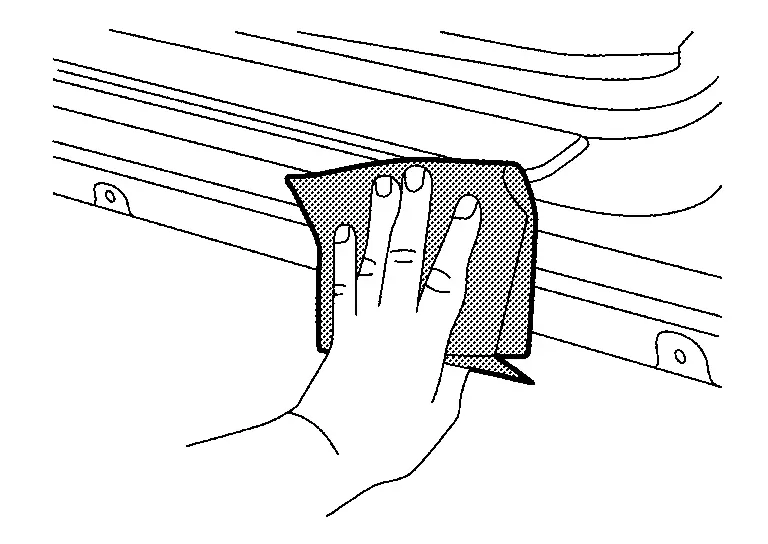
Install new door parting seal (1) by first engaging front clip in designated hole in body sill (2). Work rearward, firmly securing clips and adhesive tape.
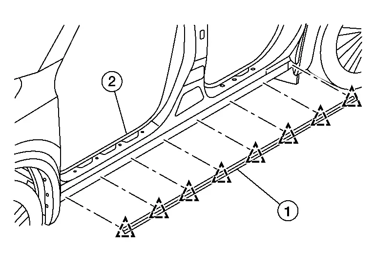
 |
: Clip |
Tow Hitch Nissan Pathfinder Fifth generation
Exploded View
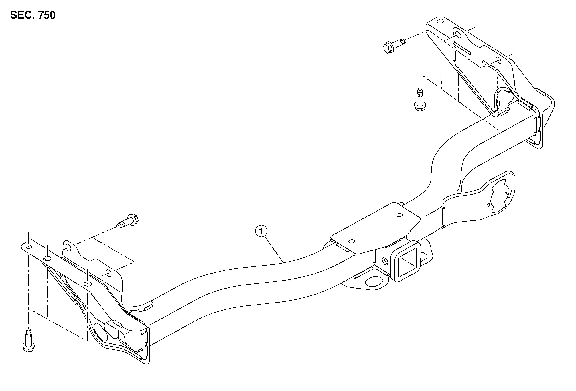
| 1. | Tow hitch |
Removal and Installation
REMOVAL
Lower the spare tire.
Disconnect the harness connectors from the trailer receptacle.
Remove tow hitch bolts. Refer to Exploded View.
Remove tow hitch.
Remove the trailer receptacle from the tow hitch (if necessary).
INSTALLATION
Installation is in the reverse order of removal.
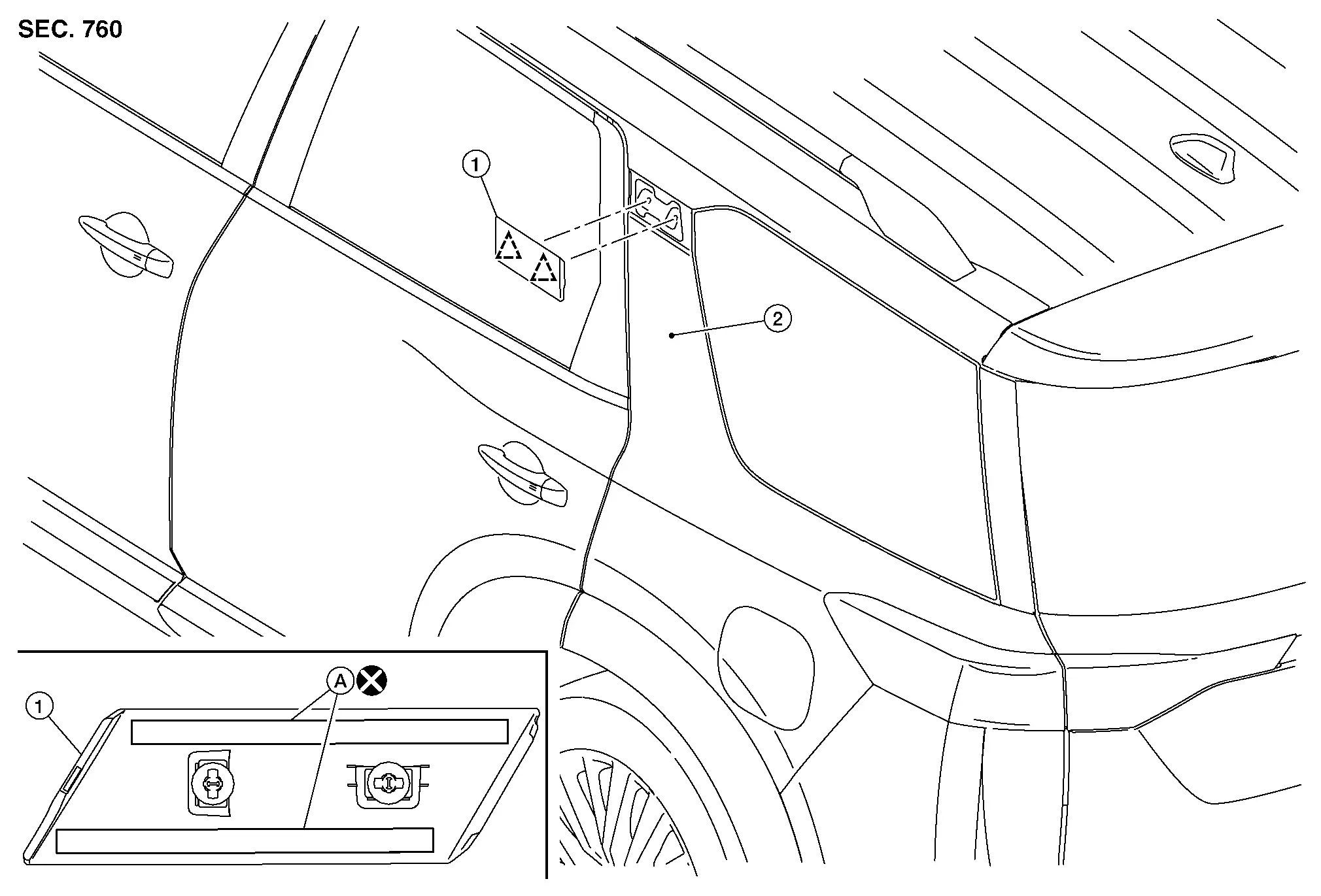
Emblem Nissan Pathfinder 2022
Exploded View
| 1. | Emblem A | 2. | Emblem B (if equipped) | 3. | Emblem C/D/E/F/G (if equipped) | 4. | Emblem H (if equipped) |
Removal and Installation
REMOVAL
Remove the emblem from the panel heating with a heat gun.
CAUTION:
Do not damage the painted surface of the panel when removing the emblem.
INSTALLATION
 NOTE:
NOTE:
-
Do not reuse the emblem.
-
Ensure Nissan Pathfinder vehicle surface temperature is between 25ºC (77ºF) to 50ºC (122ºF).
-
The following figure shows the fixing position of the emblem.
-
The central position of the left and right of emblem A should be measured between the left and right end portions of the back door assembly. Then attach the emblem at the center of the back door assembly.
Remove grease, dust, etc. from the emblem and vehicle surface.
Install the emblem to the vehicle surface.
Using a roller, or suitable tool, apply even pressure to firmly affix the emblem to Nissan Pathfinder vehicle surface.
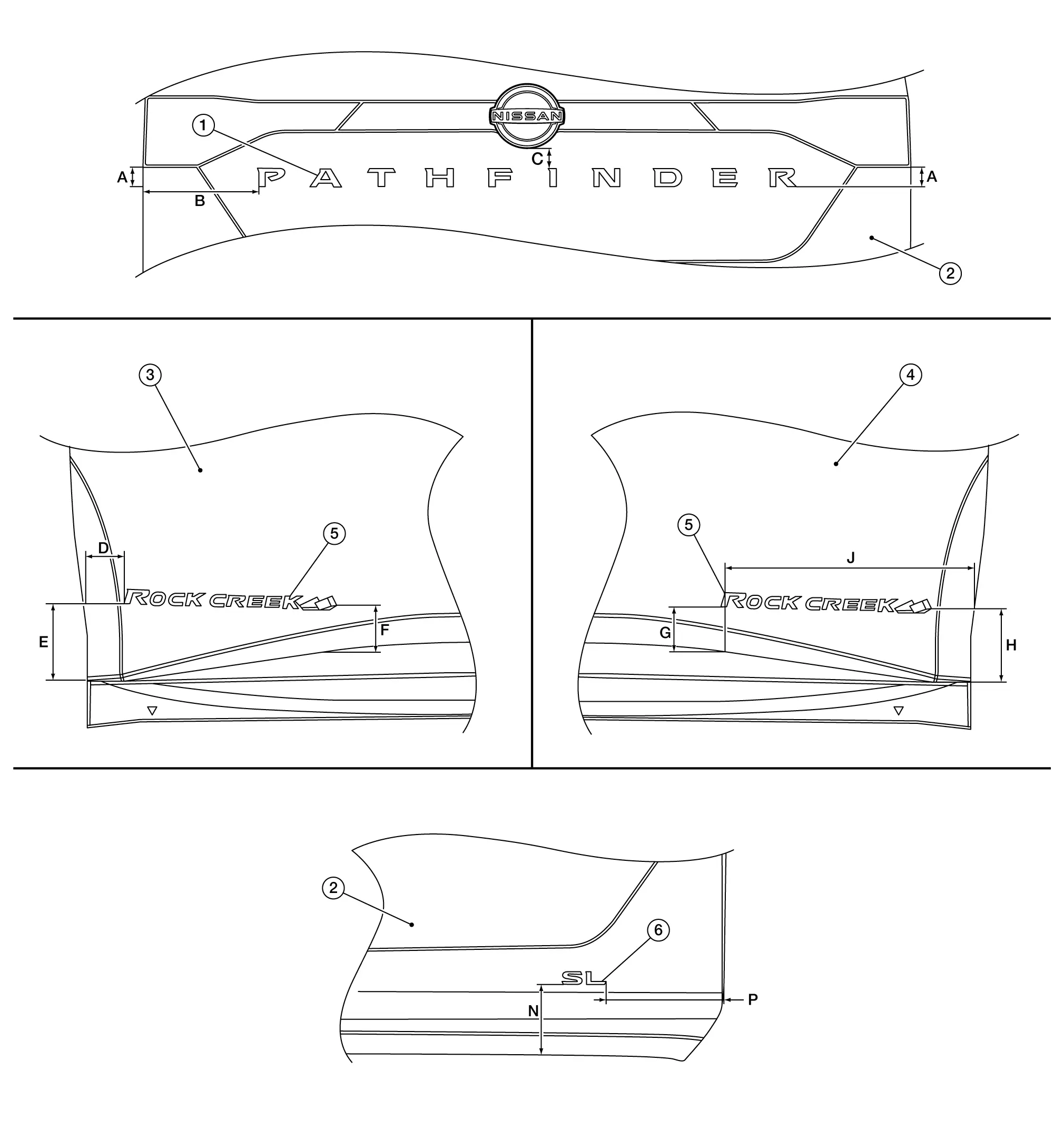
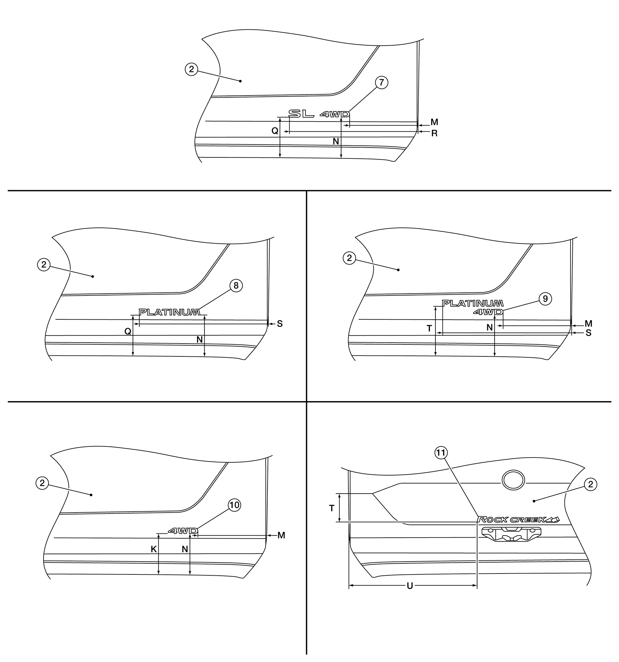
| 1. | Emblem A | 2. | Back door assembly | 3. | Driver door assembly |
| 4. | Passenger door assembly | 5. | Emblem B (if equipped) | 6. | Emblem C (if equipped) |
| 7. | Emblem D (if equipped) | 8. | Emblem E (if equipped) | 9. | Emblem F (if equipped) |
| 10. | Emblem G (if equipped) | 11. | Emblem H (if equipped) |
Unit: mm (in)
| A | : 36 (1.42) | B | : 218 (8.58) | C | : 33 (1.30) | D | : 67 (2.64) |
| E | : 130 (5.12) | F | : 93 (3.66) | G | : 86 (3.39) | H | : 138 (5.43) |
| J | : 437 (17.20) | K | : 127 (5.0) | M | : 202 (7.95) | N | : 128 (5.04) |
| P | : 207 (8.15) | Q | : 126 (4.96) | R | : 380 (14.96) | S | : 382 (15.04) |
| T | : 152 (5.98) | U | : 572 (22.52) |

Nissan Pathfinder (R53) 2022-2026 Service Manual
Removal and Installation
- Front Bumper
- Rear Bumper
- Front Grille
- Active Grille Shutter
- Cowl Top
- Roof Side Molding
- Door Outside Molding
- Rear Pillar Finisher (outer)
- Door Outside Lower Molding
- Rear Spoiler
- Back Door Outer Finisher
- Running Board
- Tow Hitch
- Emblem
Contact Us
Nissan Pathfinder Info Center
Email: info@nipathfinder.com
Phone: +1 (800) 123-4567
Address: 123 Pathfinder Blvd, Nashville, TN 37214, USA
Working Hours: Mon–Fri, 9:00 AM – 5:00 PM (EST)
