Nissan Pathfinder: Instrument Panel - Removal and Installation
- Instrument Panel Assembly
- Center Console Assembly
- Rear Center Console Assembly
- Steering Member Assembly
- Steering Column Covers
- Cluster Lid a
- Cluster Lid D
- Cluster Lid E
- Instrument Lower Panel Lh
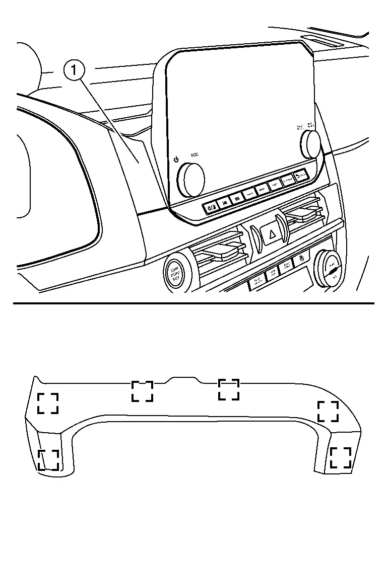
- Instrument Finisher a
- Instrument Finisher B
- Instrument Finisher C
- Instrument Finisher D
- Glove Box Assembly
Instrument Panel Assembly Nissan Pathfinder 2022
Exploded View
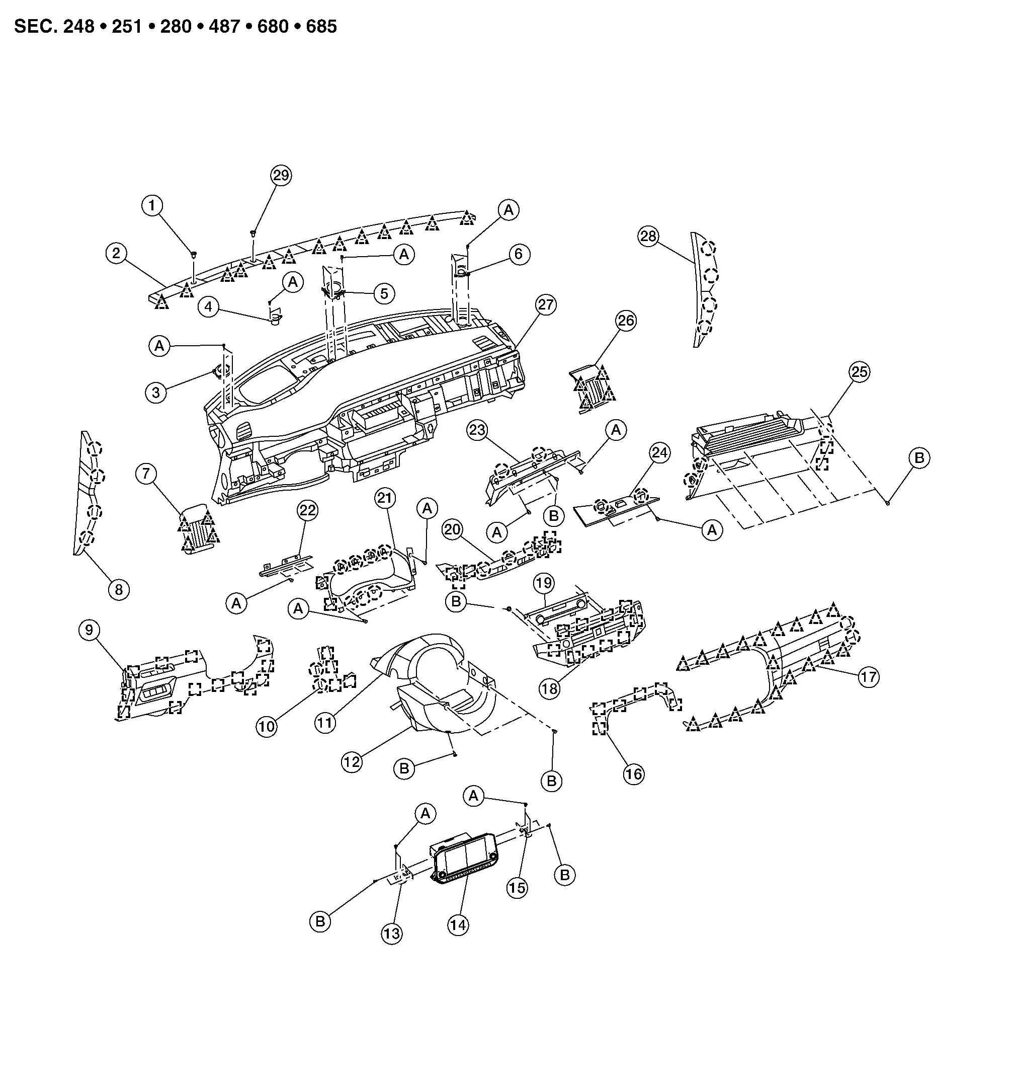
| 1. | Optical sensor | 2. | Defroster grille | 3. | Instrument panel tweeter LH |
| 4. | Master speaker | 5. | Center speaker | 6. | Instrument panel tweeter RH |
| 7. | Side ventilator grille LH | 8. | Instrument side finisher (LH) | 9. | Instrument lower panel LH |
| 10. | Instrument finisher B | 11. | Steering column upper finisher | 12. | Steering column lower finisher |
| 13. | AV control unit bracket (LH) | 14. | AV control unit | 15. | AV control unit bracket (RH) |
| 16. | Cluster lid D | 17. | Instrument finisher C | 18. | Cluster lid C |
| 19. | Front A/C switch assembly | 20. | Cluster lid E | 21. | Cluster lid A |
| 22. | Instrument finisher A | 23. | Instrument finisher D | 24. | Instrument panel undercover |
| 25. | Glove box assembly | 26. | Side ventilator grille RH | 27. | Instrument panel assembly |
| 28. | Instrument side finisher (RH) | 29. | Sunload sensor | A. | Bolt |
| B. | Screw |
 |
Metal clip |
 |
Clip |
 |
Pawl |
Removal and Installation
CAUTION:
-
Be careful not to scratch instrument panel pad and other parts.
-
Whenever a suitable tool is used, always wrap a cloth around the end of the tool to protect components from damage.
-
Before servicing, place ignition switch OFF, disconnect both battery terminals and wait at least three minutes.
REMOVAL
Disconnect the negative and positive battery terminals, then wait at least three minutes. Refer to Removal and Installation.
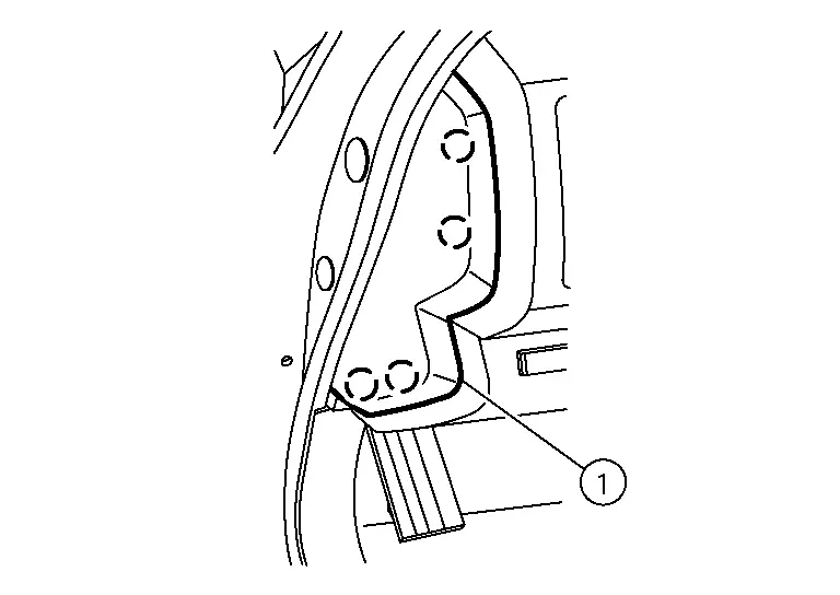
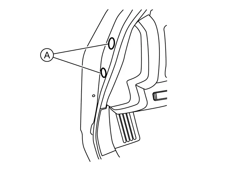
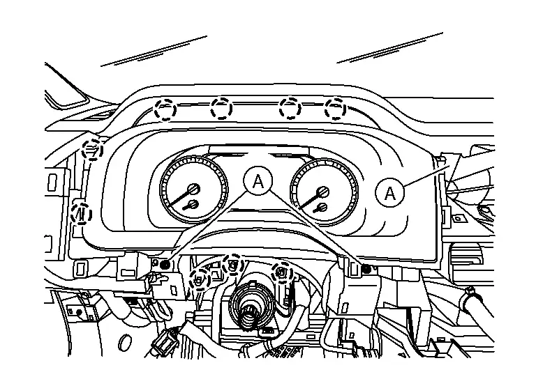
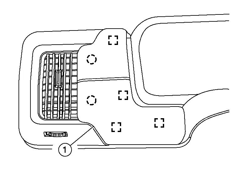
Using a suitable tool, remove instrument side finishers [(LH/RH) 1].
 NOTE:
NOTE:
LH side shown; RH side similar.
Remove front pillar finishers (LH/RH). Refer to Removal and Installation.
Remove instrument lower panel LH. Refer to Removal and Installation.
Remove combination switch. Refer to Removal and Installation.
Remove combination meter. Refer to Removal and Installation.
Remove cluster lid C. Refer to Removal and Installation.
Remove glove box assembly. Refer to Removal and Installation.
Remove defroster grille. Refer to Exploded View.
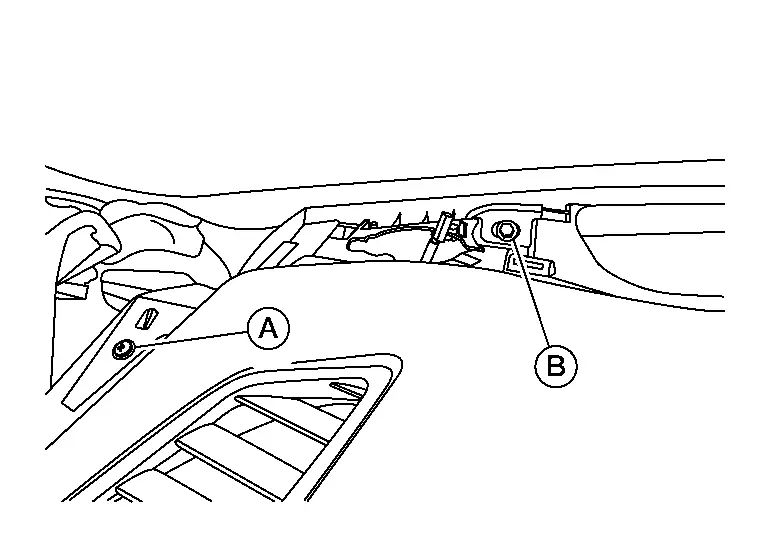
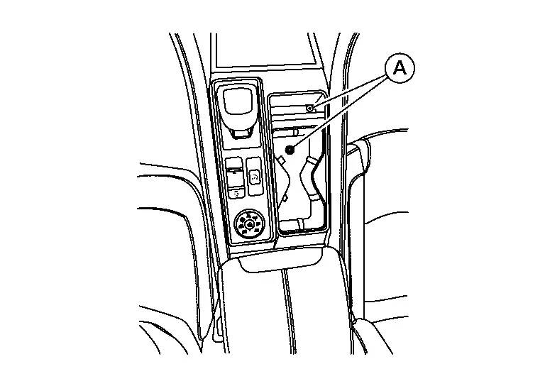
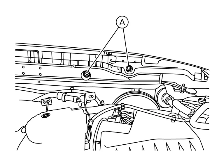
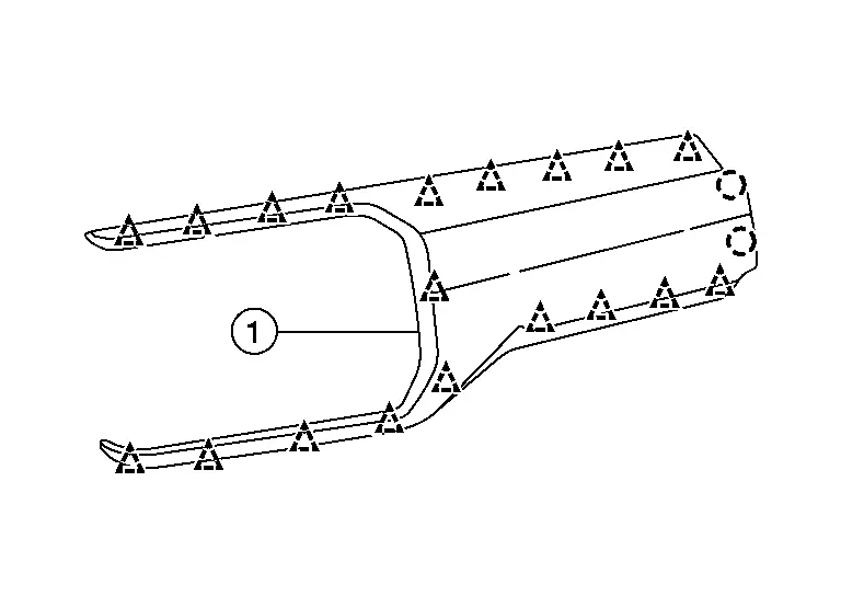
Remove instrument panel screw [A (LH/RH)] and bolt [B (LH/RH)].
 NOTE:
NOTE:
LH shown; RH similar.
Remove center console assembly. Refer to Removal and Installation.
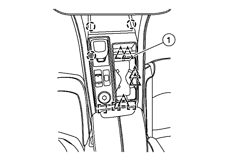
Remove instrument finisher D. Refer to Removal and Instrument.
Remove front passenger air bag module screws. Refer to Exploded View.
CAUTION:
Do not reuse the front passenger air bag module bolts and screws.
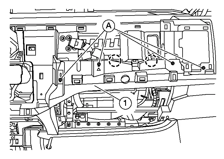
Remove instrument panel assembly screws.
Disconnect the harness connectors from the instrument panel assembly.
Remove the instrument panel assembly.
INSTALLATION
Installation is in the reverse order of removal.
CAUTION:
Do not reuse the front passenger air bag module bolts and screws.
-
If replacing the instrument panel, transfer all the necessary parts to the new instrument panel.
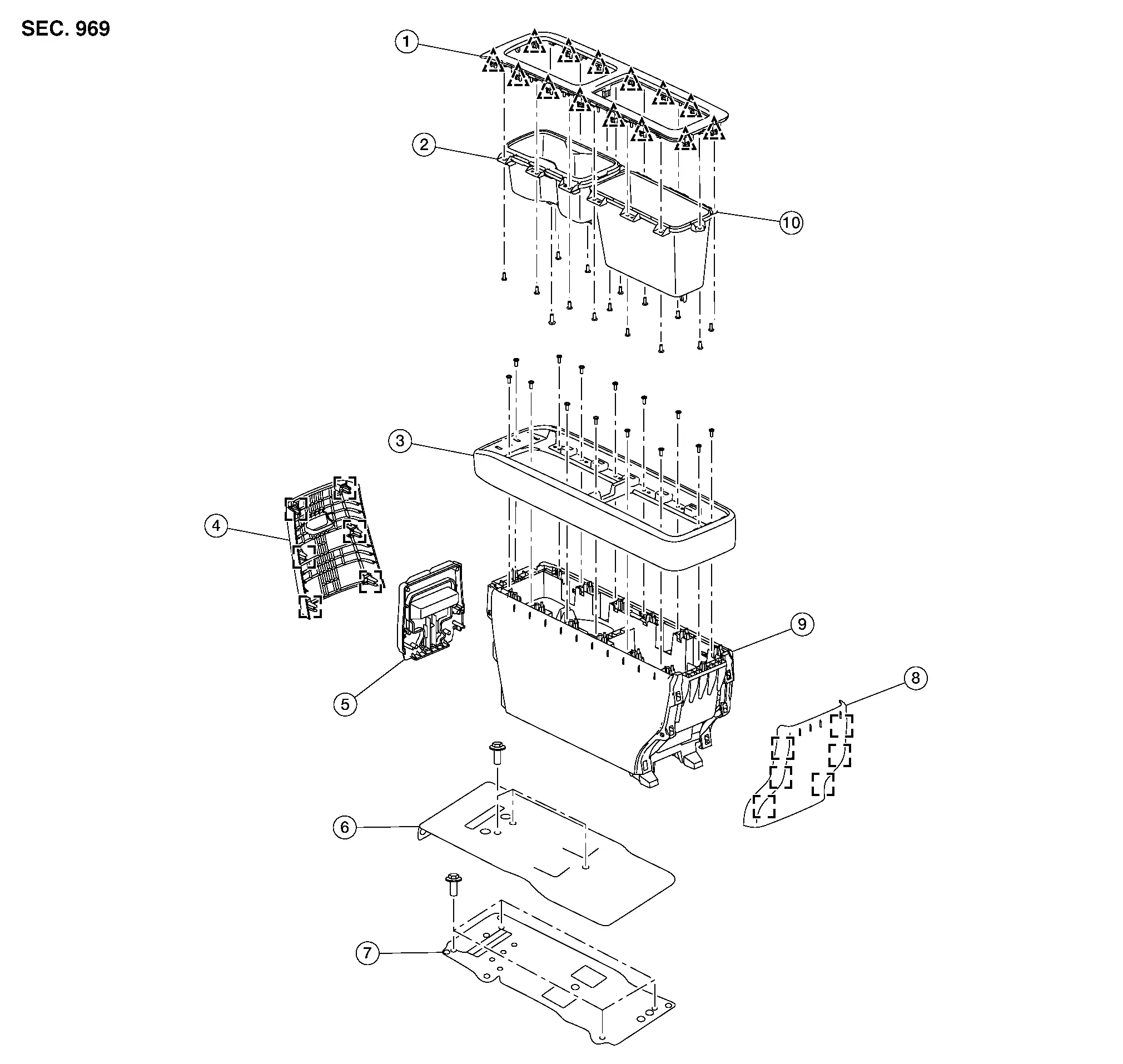
Center Console Assembly Nissan Pathfinder SUV
Exploded View
Exploded View
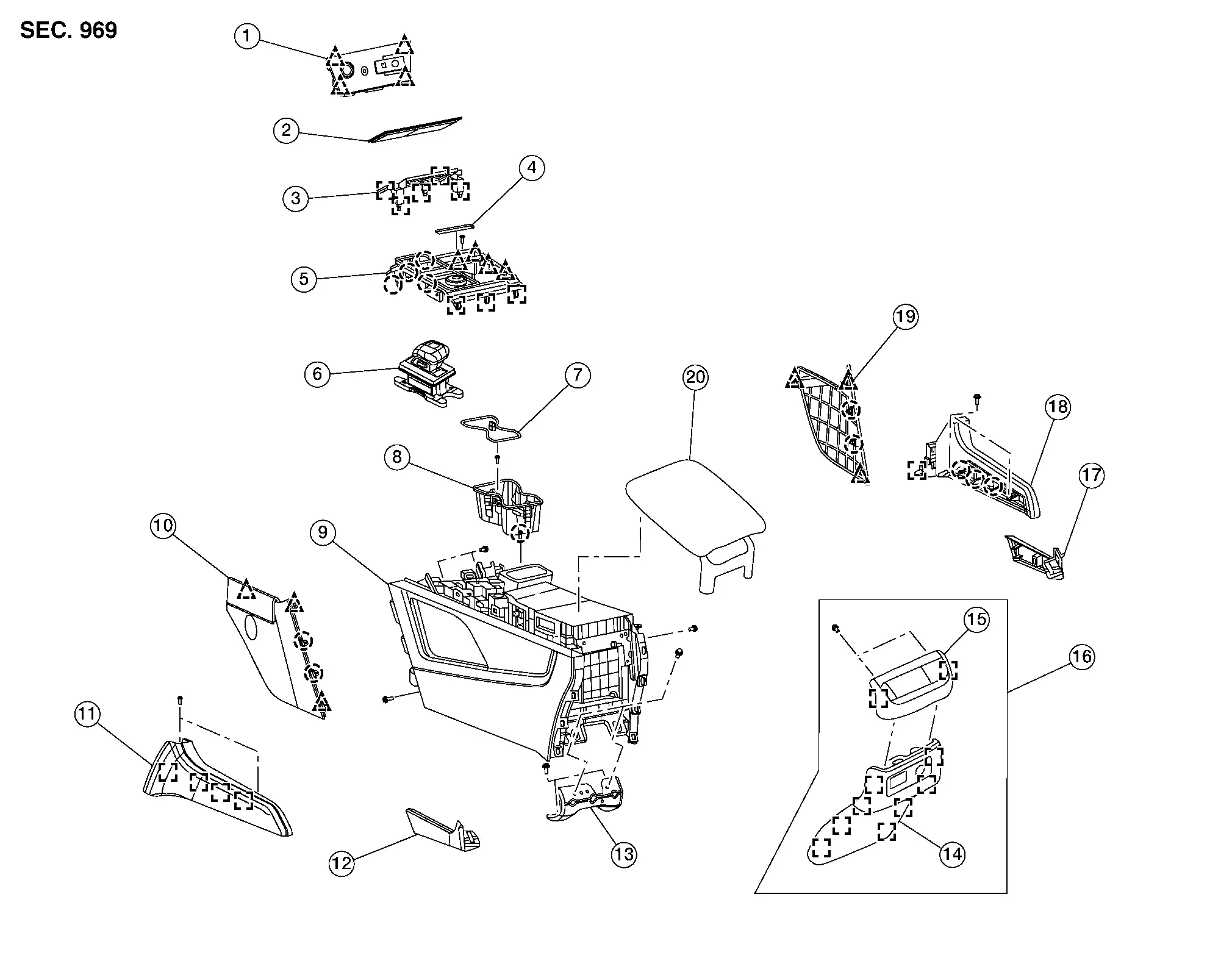
| 1. | Cluster lid C lower | 2. | Wireless charger mat (if so equipped) | 3. | Wireless charger unit (if so equipped) |
| 4. | Front console tray | 5. | Shift selector finisher | 6. | Electric shift selector |
| 7. | Cup holder mat | 8. | Cup holder finisher | 9. | Front center console assembly |
| 10. | Center console front finisher (LH) | 11. | Center console side finisher (LH) | 12. | Center console brace (LH) |
| 13. | Center console bracket | 14. | Center console rear finisher lower | 15. | Rear A/C switch assembly |
| 16. | Center console rear finisher | 17. | Center console brace (RH) | 18. | Center console side finisher (RH) |
| 19. | Center console front finisher (RH) | 20. | Center console lid |
 |
Metal clip |
 |
Clip |
 |
Pawl |
Removal and Installation
REMOVAL
CAUTION:
Be careful not to scratch center console finishers and other parts.
Remove cluster lid c lower. Refer to Removal and Installation.
Remove wireless charger unit. Refer to Removal and Installation.
Remove front console tray and cup holder mat.
Remove screws (A).
Using a suitable tool, release clips and pawls.
 |
: Metal clip |
 |
: Clip |
 |
: Pawl |
Disconnect harness connectors and remove shift selector finisher (1).
Remove bolts (A).
Using a suitable tool, release clips and remove center console front finishers [1 (LH/RH)].
 NOTE:
NOTE:
LH shown; RH similar.
 |
: Clip |
Position driver and passenger front seats to the full forward position.
Using a suitable tool, release clips and remove center console rear finisher (1).
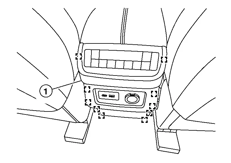
 |
: Metal clip |
Remove bolts [A (LH/RH)].
 NOTE:
NOTE:
RH shown; LH similar.
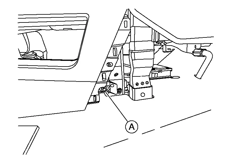
Remove bolts (A).
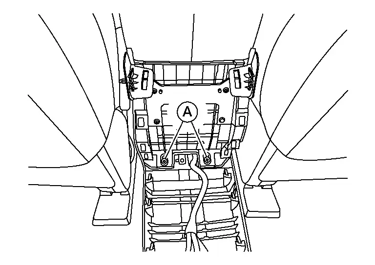
Disconnect the harness connectors and remove center console assembly.
INSTALLATION
Installation is in the reverse order of removal.
Rear Center Console Assembly Nissan Pathfinder SUV
Exploded View
Exploded View
| 1. | Cup holder finisher | 2. | Cup holder | 3. | Rear center console trim |
| 4. | Pull handle finisher | 5. | Pull handle release | 6. | Rear center console base |
| 7. | Rear center console brace | 8. | Rear center console finisher | 9. | Rear center console assembly |
| 10. | Rear center console storage |
 |
Metal clip |
 |
Clip |
Removal and Installation
Using a suitable tool, release clips and remove pull handle finisher (1).
 |
: Metal clip |
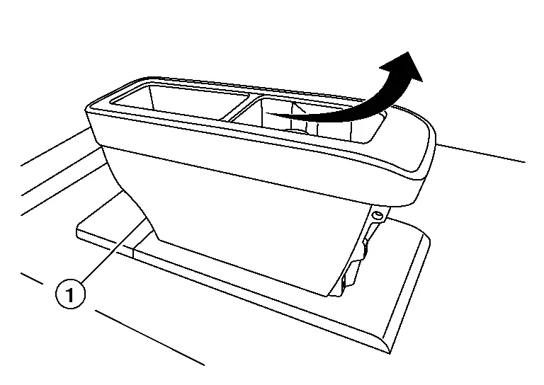
Release latch (A) as shown.
Remove rear center console (1) as shown.
INSTALLATION
Installation is in the reverse order of removal.
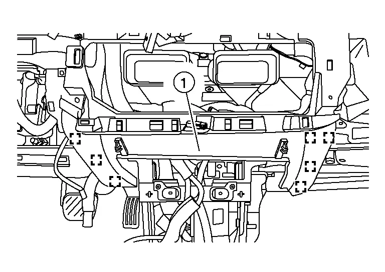
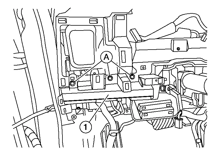
Steering Member Assembly Nissan Pathfinder
Exploded View
Exploded View
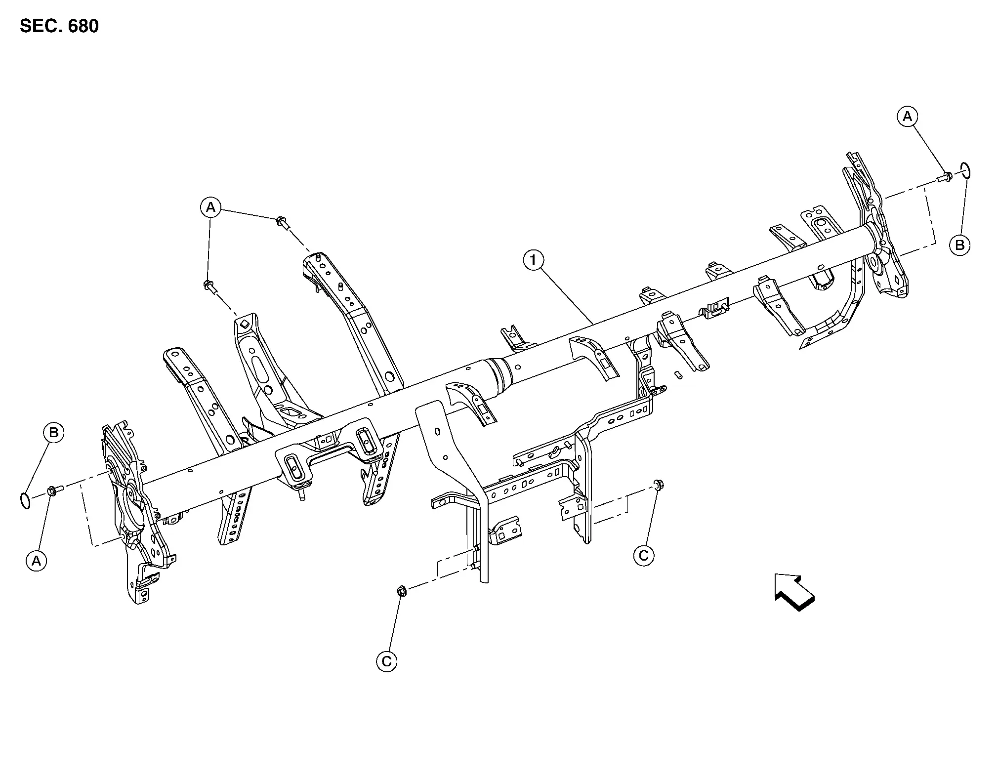
| 1. | Steering member assembly | A. | Bolt | B. | Dust cover |
| C. | Nut |
 |
Front |
Removal and Installation
REMOVAL
 NOTE:
NOTE:
When removing components such as hoses, lines/tubes, etc., cap or plug openings to prevent fluid from spilling.
Drain engine coolant. Refer to Draining.
CAUTION:
-
Perform this step when the engine is cold.
-
Do not spill engine coolant on the drive belt.
Recycle the refrigerant. Refer to Recycle Refrigerant.
Remove instrument panel assembly. Refer to Removal and Installation.
Remove cowl top extension. Refer to Removal and Installation.
Remove bolt and separate high-pressure and low-pressure pipe from front heating and cooling unit assembly. Refer to Exploded View.
CAUTION:
Cap or wrap the joint of the pipe with suitable material such as vinyl tape to avoid the entry of air.
Release clamps and separate heater hoses from front heater core.
Remove knee air bag module LH. Refer to Removal and Installation.
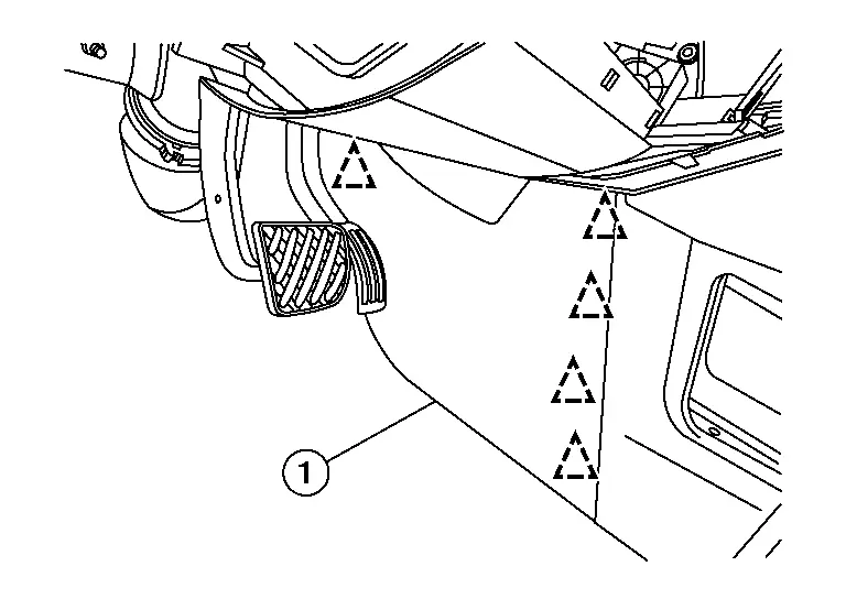
Remove foot lamp (RH side). Refer to Removal and Installation.
Remove knee air bag module RH. Refer to Removal and Installation.
Remove BCM. Refer to Removal and Installation.
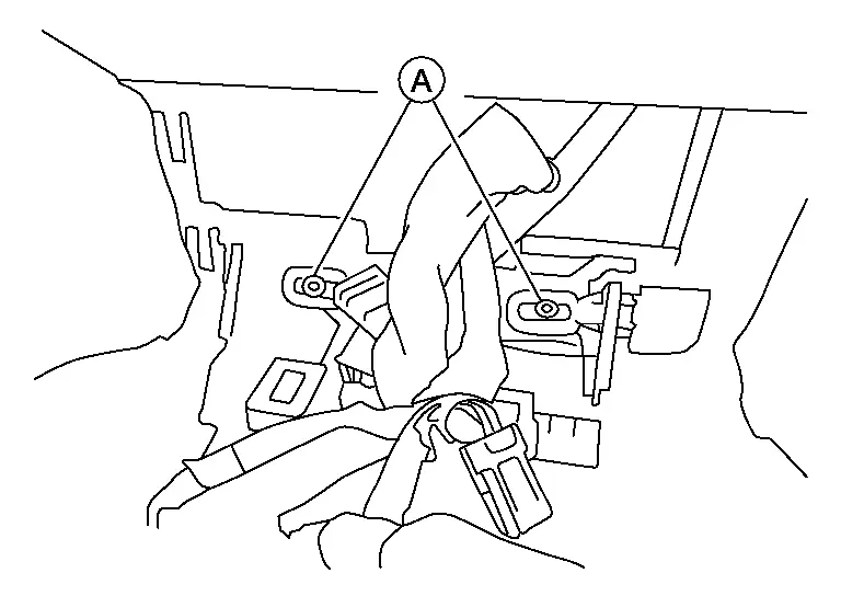
Remove bolt and separate lower joint from steering gear. Refer to Exploded View.
Disconnect the harness connector from the fuse panel near the LH pillar.
Remove fuse panel and set aside.
Remove front floor connecting duct (LH/RH). Refer to Removal and Installation.
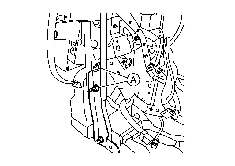
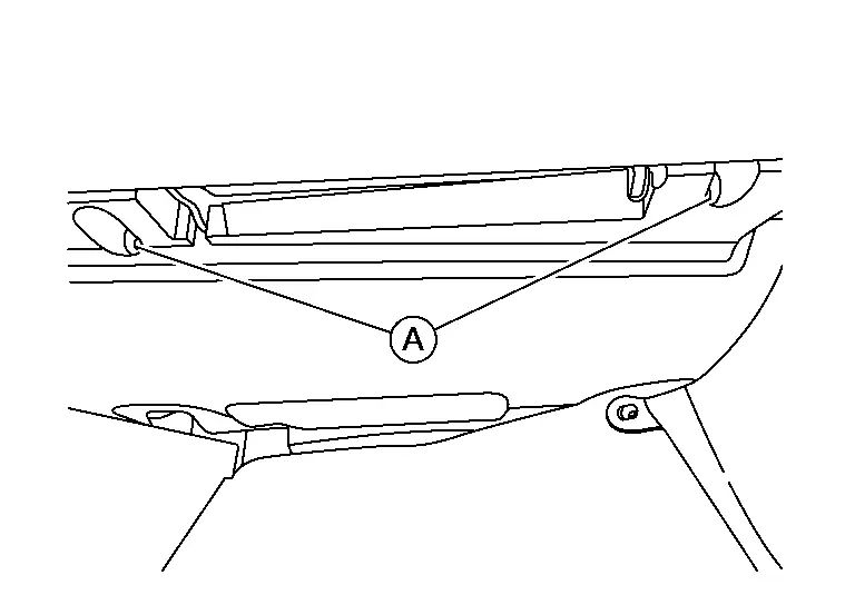
Remove dust covers and remove bolts (A).
Using a suitable tool, remove bolt covers [A (LH/RH)] and remove bolts.
 NOTE:
NOTE:
LH shown; RH similar.
Remove bolts [A (LH/RH)].
 NOTE:
NOTE:
LH shown; RH similar.
Separate drain hose from front heating and cooling unit assembly.
Disconnect harness connectors and remove steering member assembly.
INSTALLATION
Installation is in the reverse order of removal.
-
Refill engine coolant. Refer to Refilling.
-
Check cooling system for leaks. Refer to System Inspection.
CAUTION:
-
Perform “ADDITIONAL SERVICE WHEN REPLACING HEAD UP DISPLAY UNIT” (if equipped). Refer to Work Procedure.
-
Apply A/C oil to the O-rings of the high-pressure and low-pressure pipe for installation.
-
After charging the refrigerant, check for leaks. Refer to Leak Test.
Steering Column Covers Nissan Pathfinder 2022
Removal and Installation
REMOVAL
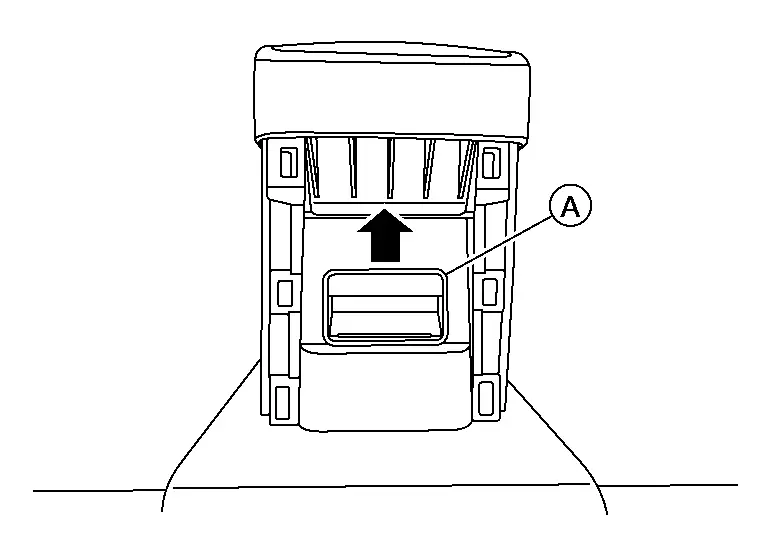
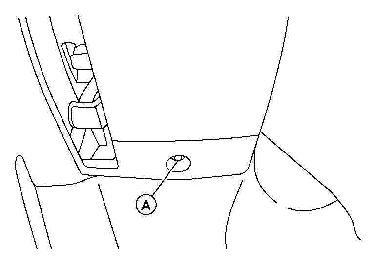
Rotate steering wheel counterclockwise and remove screw (A).
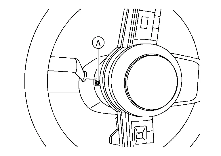
Rotate steering wheel clockwise and remove screw (A).
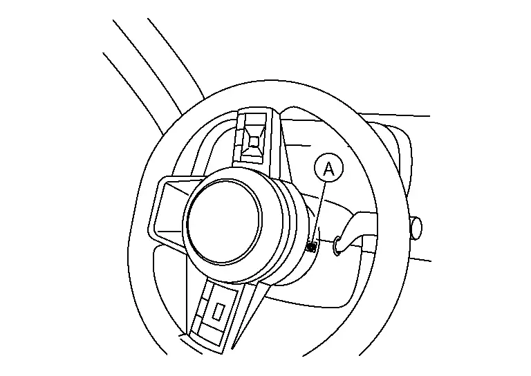
Remove screw (A).
Using a suitable tool, release steering column lower shroud (1) pawls.
 |
: Pawl |
Using a suitable tool, release cluster lid A shroud (1) pawls.
 |
: Pawl |
Disconnect harness connector (if so equipped) and remove steering column covers.
INSTALLATION
Installation is in the reverse order of removal.
Cluster Lid a Nissan Pathfinder
Removal and Installation
REMOVAL
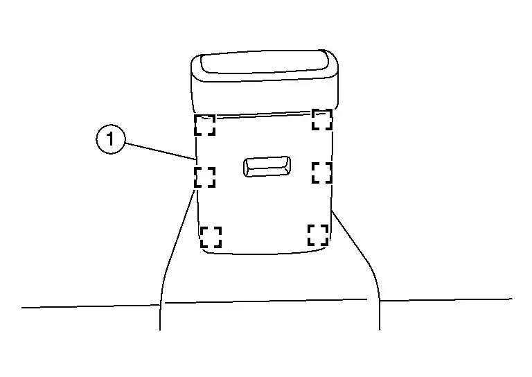
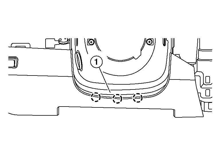
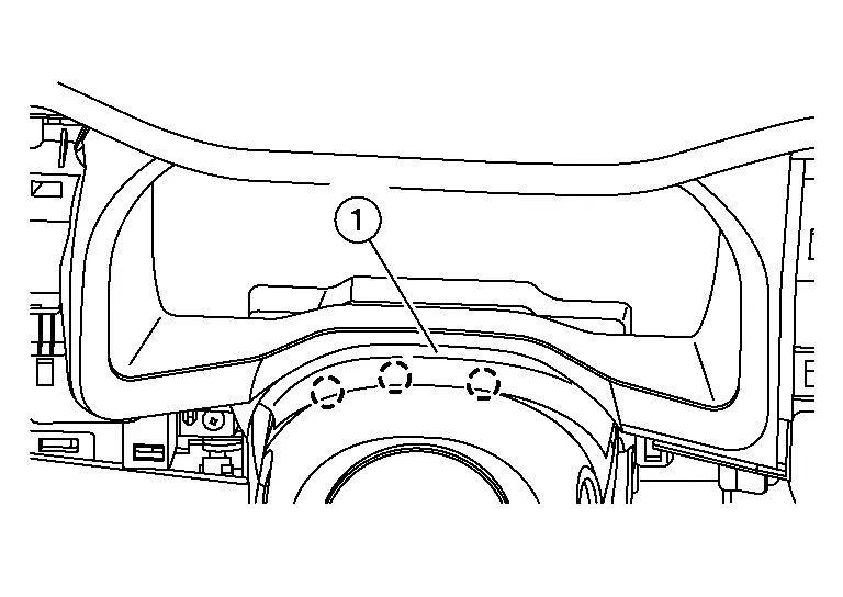
Using a suitable tool, release pawls and remove instrument side finisher [1 (LH)].

 |
: Pawl |
Remove instrument lower panel LH. Refer to Removal and Installation.
Remove instrument finisher A. Refer to Removal and Installation.
Remove AV control unit. Refer to Removal and Installation.
Remove cluster lid D. Refer to Removal and Installation.
Using a suitable tool, remove screws (A) then release pawls.
 |
: Pawl |
Remove cluster lid A.
INSTALLATION
Installation is in the reverse order of removal.
Cluster Lid D Nissan Pathfinder
Removal and Installation
REMOVAL
Remove instrument finisher C. Refer to Removal and Installation.
Using a suitable tool, release clips and remove Cluster lid D (1).
 |
: Metal clip |
INSTALLATION
Installation is in the reverse order of removal.
Cluster Lid E Nissan Pathfinder 2022
Removal and Installation
Remove cluster lid C. Refer to Removal and Installation.
Remove center console assembly. Refer to Removal and Installation.
Using a suitable tool, release clips and remove cluster lid E (1).
 |
: Metal clip |
INSTALLATION
Installation is in the reverse order of removal.
Instrument Lower Panel Lh Nissan Pathfinder SUV
Removal and Installation
REMOVAL
Using a suitable tool, release pawls and remove instrument side finisher [1 (LH)].

 |
: Pawl |
Using a suitable tool, release instrument lower panel LH (1) clips.

 NOTE:
NOTE:
Instrument panel lower LH shown with switch panel; Instrument panel lower LH without switch panel similar.
 |
: Metal clip |
Disconnect aspirator hose and harness connectors.
Remove instrument lower panel LH.
INSTALLATION
Installation is in the reverse order of removal.
Instrument Finisher a Nissan Pathfinder R53
Removal and Installation
Remove instrument finisher B. Refer to Removal and Installation.
Remove side ventilator grille (LH). Refer to Removal and Installation (LH).
Remove instrument lower panel LH. Refer to Removal and Installation.
Remove screws (A) and remove instrument finisher A (1).
INSTALLATION
Installation is in the reverse order of removal.
Instrument Finisher B Nissan Pathfinder
Removal and Installation
Using a suitable tool, release metal clips and pawls.
 |
: Metal clip |
 |
: Pawl |
Remove instrument finisher B (1).
INSTALLATION
Installation is in the reverse order of removal.
Instrument Finisher C Nissan Pathfinder 2022
Removal and Installation
Using a suitable tool, release clips and pawls.
 NOTE:
NOTE:
Instrument finisher C shown removed for clarity.
 |
: Clip |
 |
: Pawl |
Remove instrument finisher C (1).
INSTALLATION
Installation is in the reverse order of removal.
Instrument Finisher D Nissan Pathfinder SUV
Removal and Installation
Remove instrument lower panel LH. Refer to Removal and Installation.
Remove cluster lid C. Refer to Removal and Installation.
Remove glove box assembly. Refer to Removal and Installation.
Remove side ventilator grille (RH). Refer to Removal and Installation (RH).
Remove screws (A).
 |
: Pawl |
Remove instrument finisher D (1).
INSTALLATION
Installation is in the reverse order of removal.
Glove Box Assembly Nissan Pathfinder 2022
Removal and Installation
REMOVAL
Using a suitable tool, release pawls and remove instrument side finisher [1 (RH)].

 |
: Pawl |
 NOTE:
NOTE:
LH shown; RH similar.
Remove glove box assembly lower screws (A).
Open glove box lid, then remove the glove box assembly upper screws (A).
Using a suitable tool, release pawls and clips.
 |
: Metal clip |
 |
: Pawl |
Disconnect the harness connectors and remove glove box assembly.
INSTALLATION
Installation is in the reverse order of removal.

Nissan Pathfinder (R53) 2022-2026 Service Manual
Removal and Installation
- Instrument Panel Assembly
- Center Console Assembly
- Rear Center Console Assembly
- Steering Member Assembly
- Steering Column Covers
- Cluster Lid a
- Cluster Lid D
- Cluster Lid E
- Instrument Lower Panel Lh
- Instrument Finisher a
- Instrument Finisher B
- Instrument Finisher C
- Instrument Finisher D
- Glove Box Assembly
Contact Us
Nissan Pathfinder Info Center
Email: info@nipathfinder.com
Phone: +1 (800) 123-4567
Address: 123 Pathfinder Blvd, Nashville, TN 37214, USA
Working Hours: Mon–Fri, 9:00 AM – 5:00 PM (EST)
